Introduction
The week started with a Basic Electronics Class from one of our Instructors Vinod . It was all about fundamentals of Electronics followed by the overview and descriptions of Electronic components like resistors, capacitors, inductors, transistors etc. The class also covered the micro controller, micro processor part , along with the function of all the pins like MISO, MOSI, SCK(clock) , Input/Output pins, reset pin etc. He also explained about all the PCB milling materials, different tool bits used for milling, then about the Roland Milling machine and about setting up the tool.
This week I was prepared for anything as I am a Noobie to the Electronics field and expected it to be tougher than normal.
PCB Milling
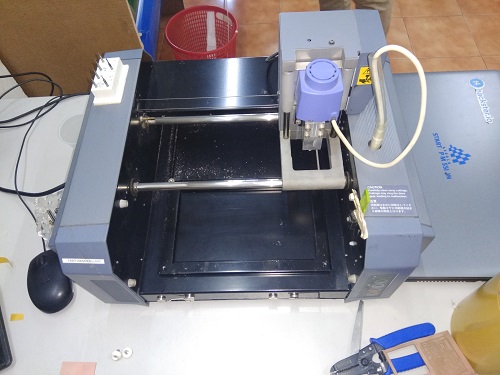
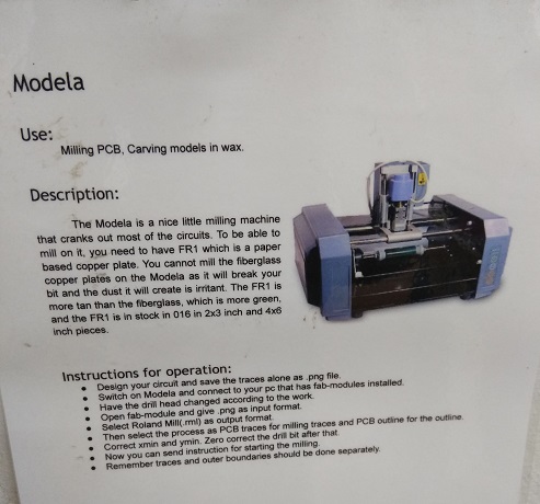
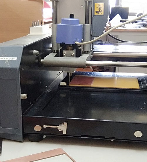
At our Fablab we have a Roland Modela Milling Machine.
The tool bits we use are the two kinds of endmills, 1/64" for mmaking the traces to the boards and 1/32" to cut the boards. End Mill tools are those tools different from other drill bits , and they have tooth on the sides. On action they rotate and cuts the PCB to move the residue up through the tooth path.
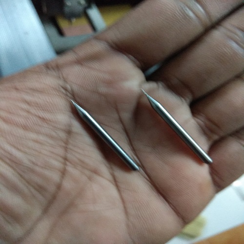
The tool bits
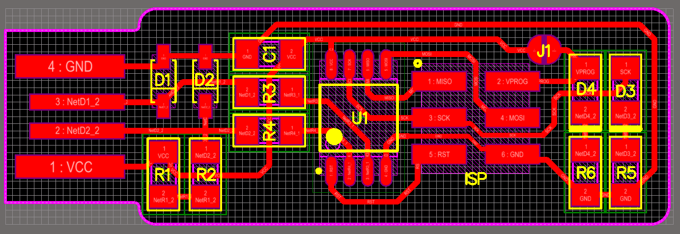
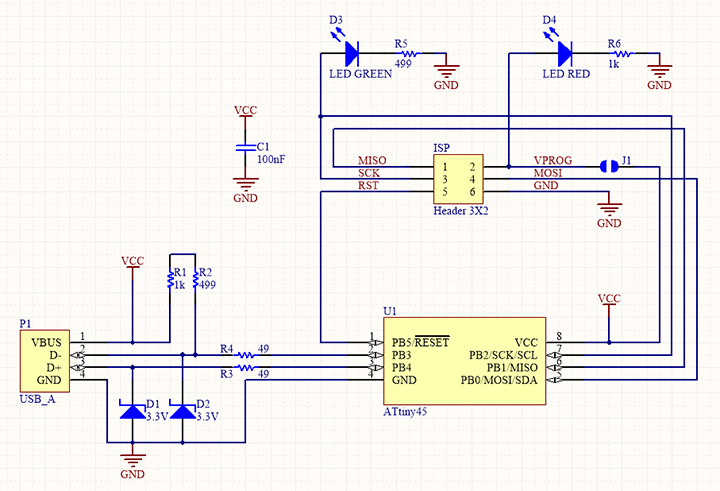
Selecting the Brian's ISP
Going through our Schedule of Week 5 assignments, read about different ISPs made in fab academy. Brian's one is the simplest and tidiest with less space.
Fab Module
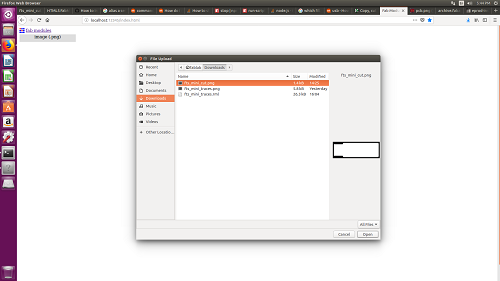
Unlike for the vinyl cutting we used the online version of Fab Module to make all the settings for milling the PCB. I downloaded the png file of usb trace from Brian's page and also the cutting outline image.
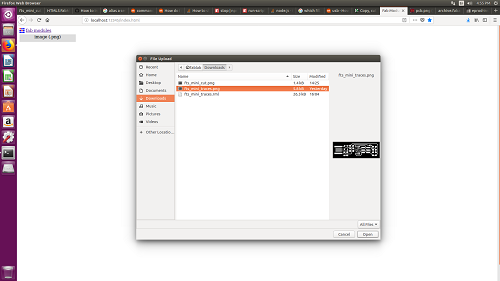
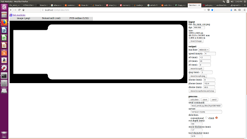
The trace image was opened in the Fabmodule
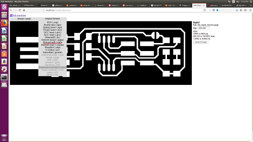
Roland Milling Machine .rml output file was selected
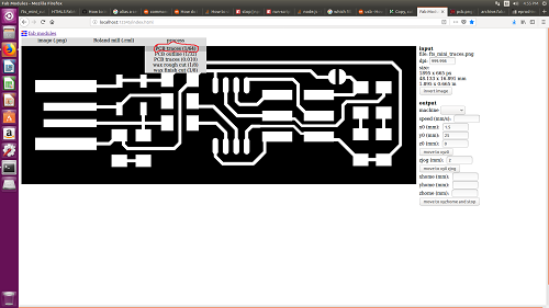
Pre-settings for the 1/64" was selected.
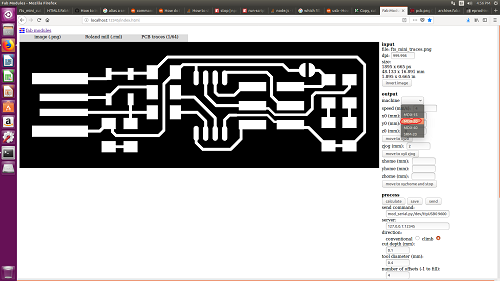
Output machine was selected as MDX-20
Origin was set with x-axis and y-axis, the speed was set to 3
The depth of cut was 0.1mm, number of offset was given 4, offset overlap 50% and error pixels 1.1
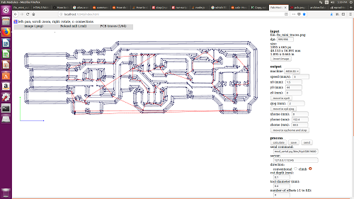
When calculating the process, we get a tool path during the machining.
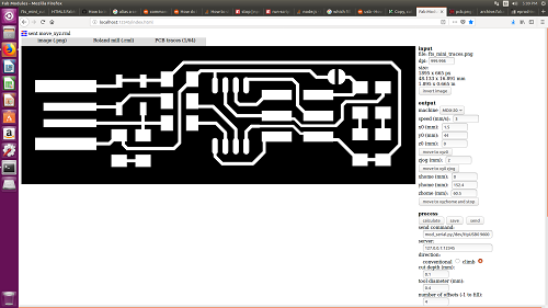
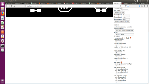
After making the circuit on the board, we now have to cut the USB outlinefrom the board. So i opened the cuting outline image on Fabmodule
The Origin was set the same as our trace image, the depth of cut was given 0.6mm and offset as 1.
Setting the Machine
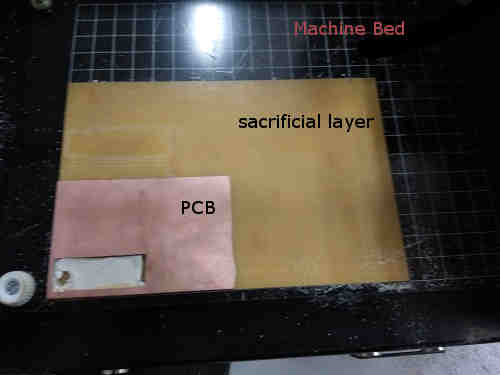
Machine bed with sacrificial layer on top of it and PCB on top of sacrificial layer
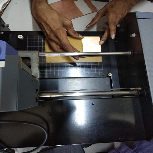
Sticking the PCB on the sacrificial layer with double sided stickers
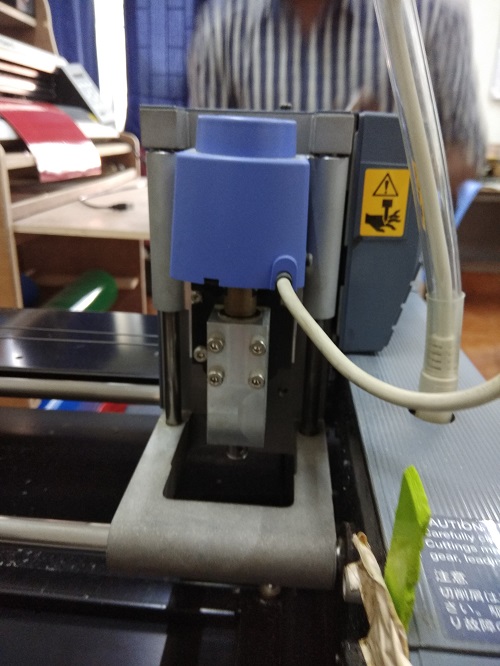
Tool Head
Setting the tool
Group Project
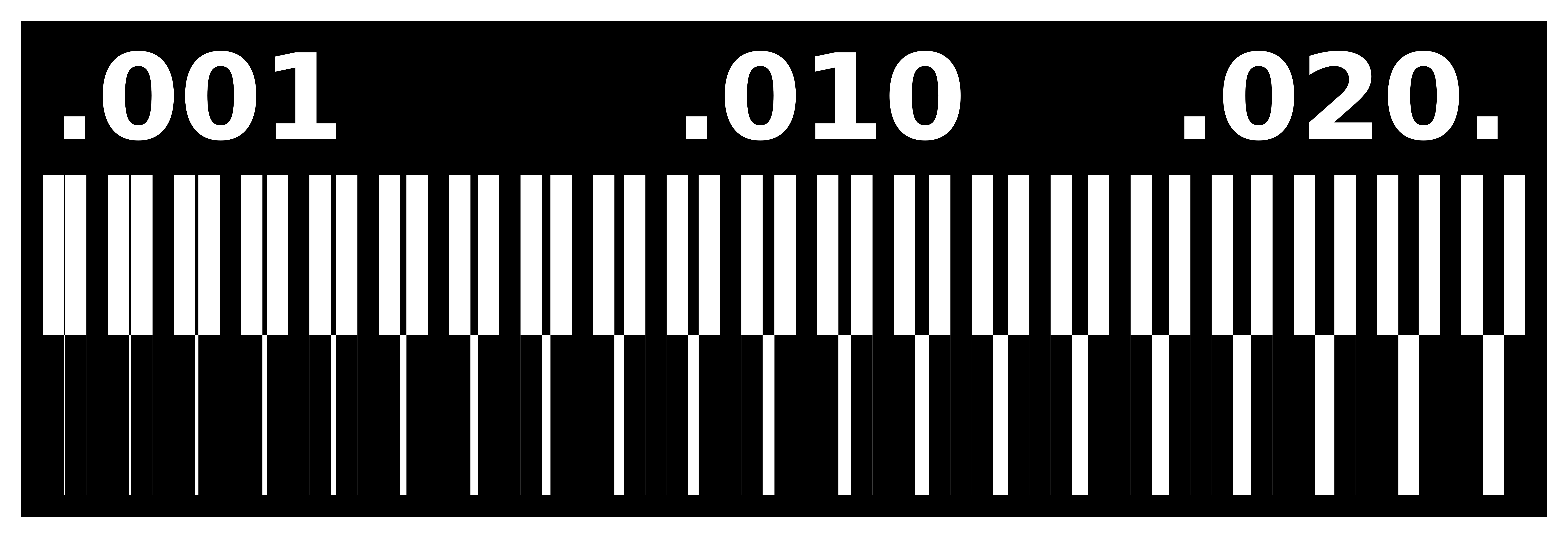
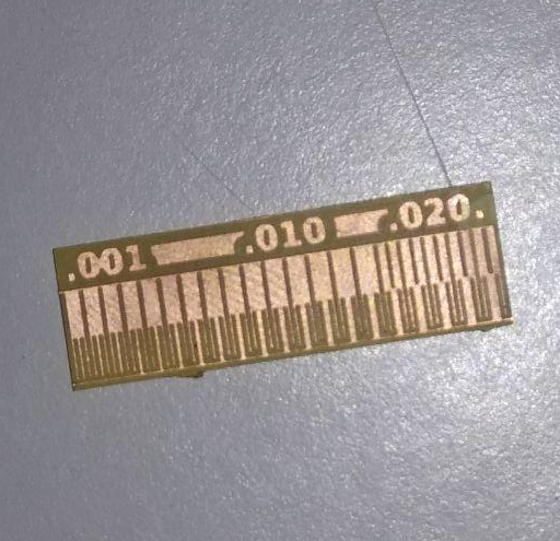
Characterizing the specification of our PCB production process
While milling with the tool bit 1/64" we found that it is only able to mark trace upto 0.20, It doesnt have the accuracy to mill the thickness of 0.001 and 0.01.
Group Project
Making the Circuit board
We use 1/64" tool bit for the tracing through copper. The tool was fixed and i entered the image input, then changed the process to 1/64" milling , made the speed to 3, cut depth 0.1mm and made the cut. All was safe and the tracing was perfect. The machine finishes of all the unwanted copper from the board to make the circuit.
Making the cut for the USB outline
We usel 1/34" tool bit for the cutting of the board for making my ISP usb. I changed my tool and changed the procees to 1/34" millling, there was my PCB. I took the cut piece and cleaned it, now its time for some soldering.
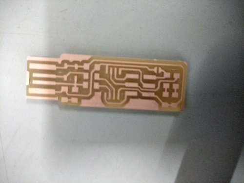
End Product after the milling process
Making the In System Processor ISP usb
First i collected all the required SMD (surface mount) components from our Electronics rack
Tools : Soldering Station, soldering lead , soldering gun, tweezers, flex, de-solder and a Magnifying lens plus lamp, also a step- down transformer for the soldering station.
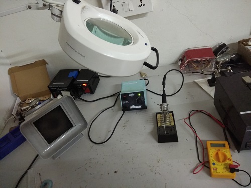
Tools and apparatus for soldering
I started soldering with IC first, it was quiet easy, we should have to just check the orientation of the IC while placing on the PCB. Then i took the two zener diodes, diodes are very small and the polarity is so difficult to see without the magnifier. It took me some time to solder them. And i soldered resistors, then capacitor , Leds and then atlast the Pin. I later came to know that I placed green and red LEDs in the wrong order, And also the solder on my Pin was not perfect at first.
I followed Brian's page for all the finishing on my solder work, i flow some solder onto the USB contacts on the board to build them up a little bit. Heated the pad and apply solder, moving the iron tip along the pad to distribute it. Once you have enough solder, wipe the iron tip across the pad in one continuous motion to even it out into a smooth layer. If you don't get a smooth layer, you need more flux: clean off your iron tip on the sponge, apply a little more solder to the pad, and wipe across it again. Excess solder will come away on the iron. Eventhough i tried to make it tidy, mine was only just okay . Then i checked all my connections and the connection between the Vcc and Ground Gnd with a multimeter.
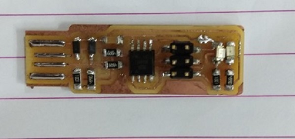
My ISP after soldering
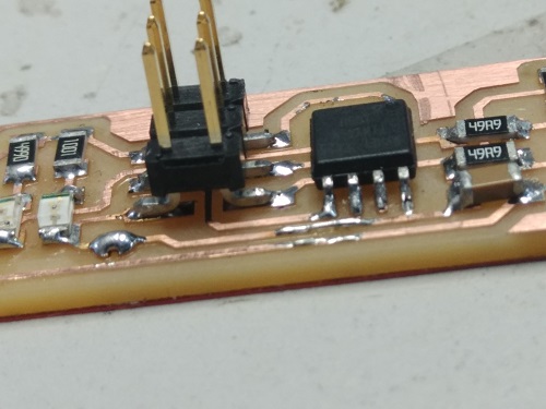
Zoomed picture
ISP Programming
After all the physical setup of my processor, now i have to flash it with a programmer to make it work. For programming my ISP, i took the ISP of my Instructor Yedu. So first I connected the jumper wires from my ISP Ic to other programmer ISP, Matching all the pins.
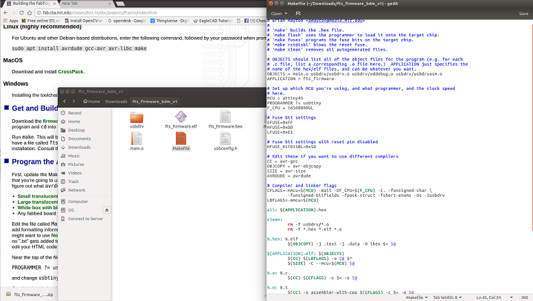
I installed the AVR with the command
sudo apt install avrdude gcc-avr avr-libc make
on the terminal.
Downloaded the firmware source code and extract the zip file.
Open your terminal
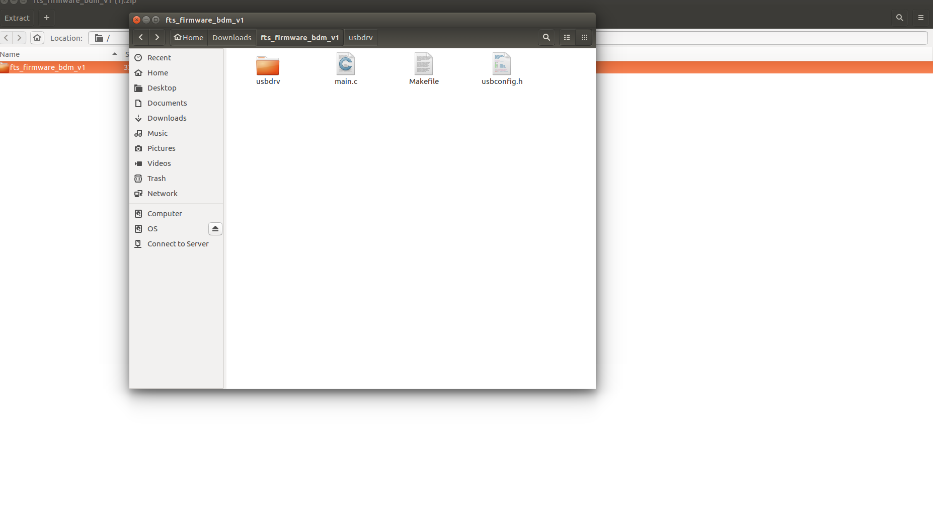
Extracted Firmware Source Code Folder
Now connect the programmer ISP to USB port and my ISP connected to programmer ISP with a USB extension cable, make sure the MISO and MOSI are connected corrctely on both.
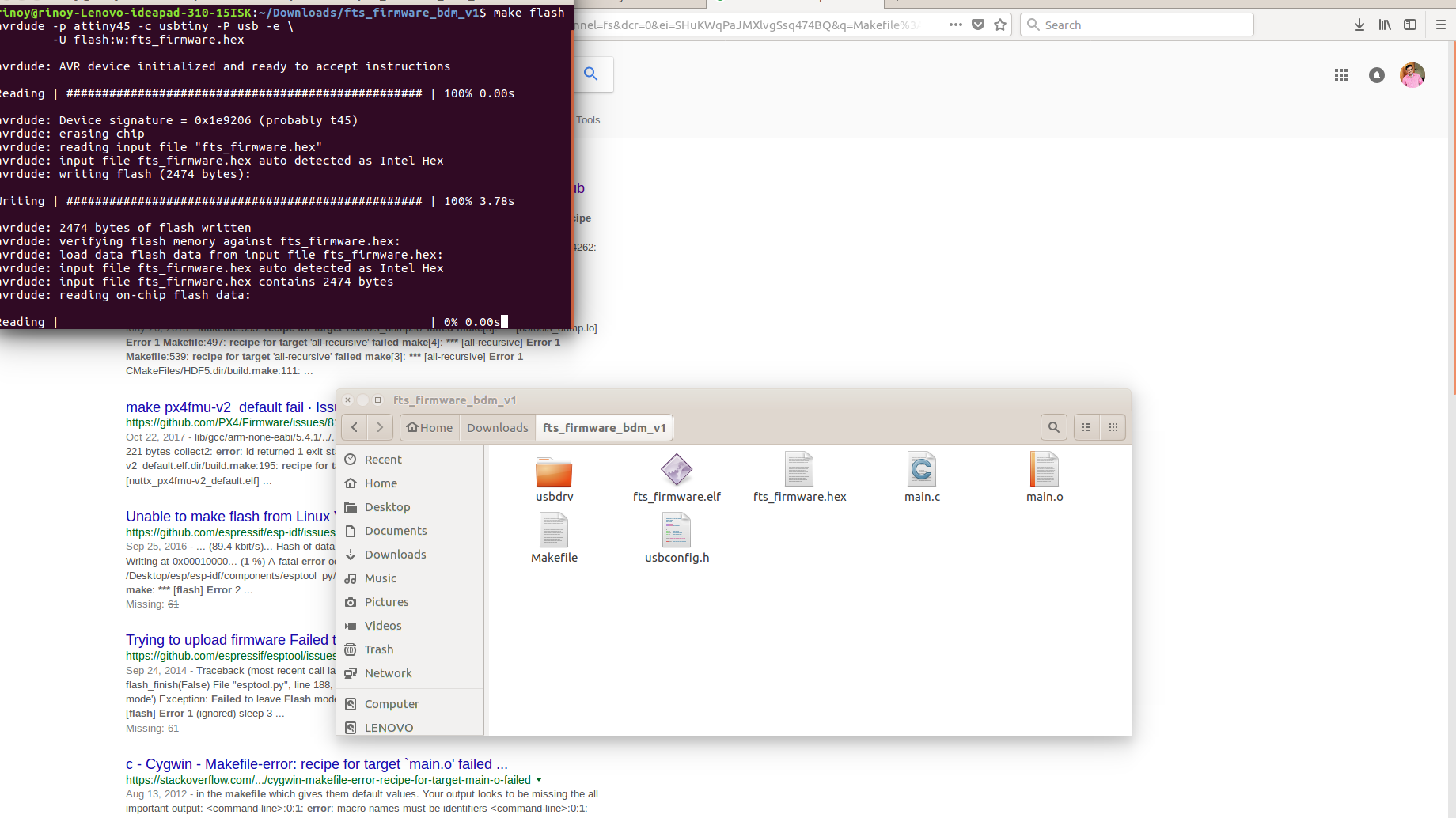
Now run
make flash
command
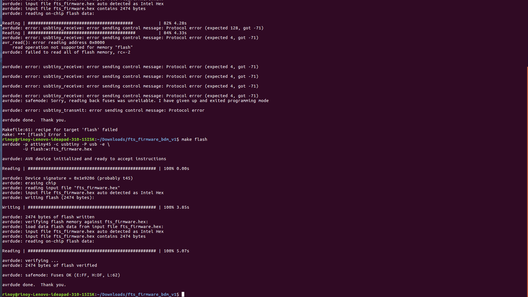
Flashing and fusing my ISP
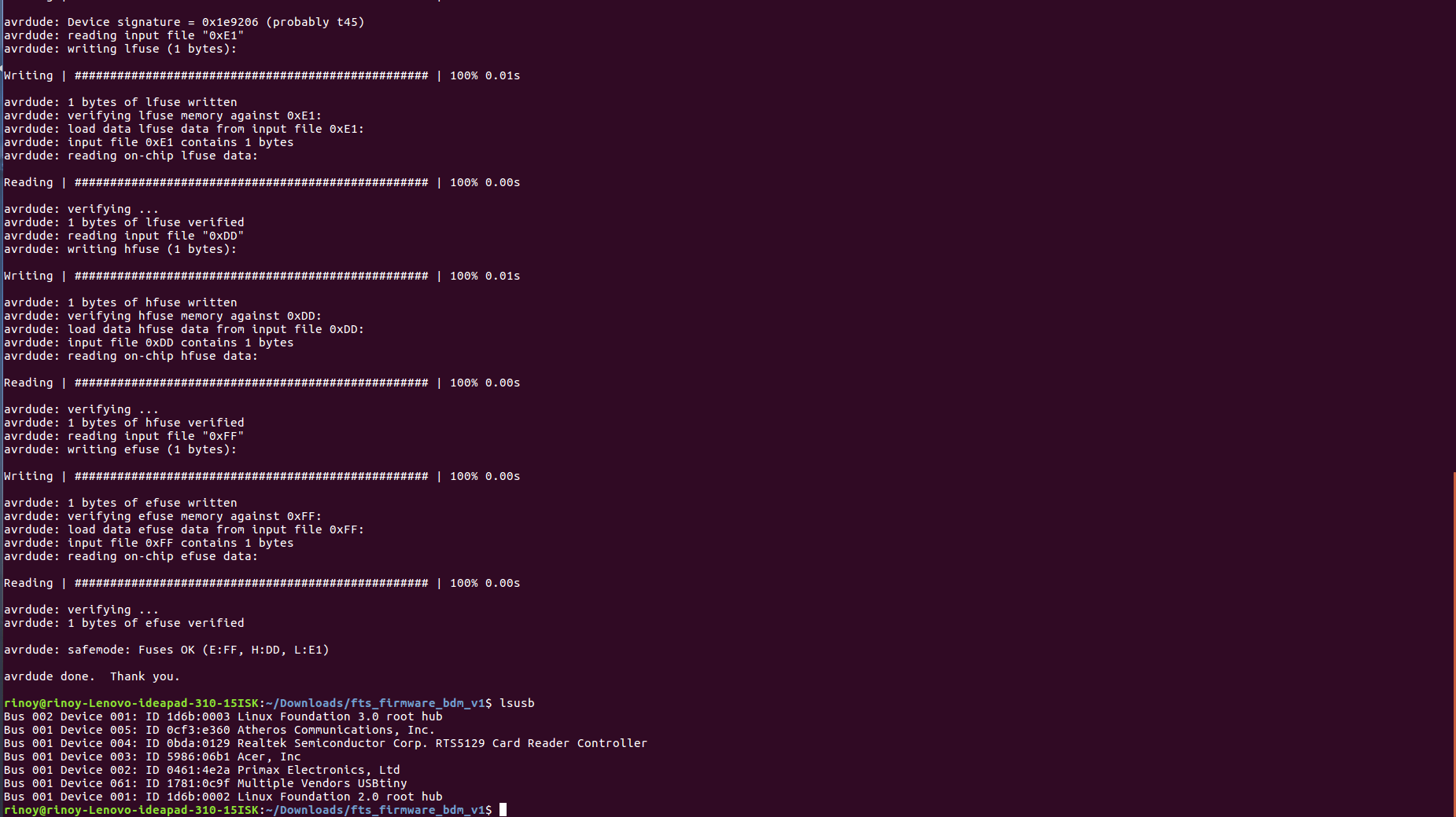
Fusing and checking my USBtiny
As i connected again with the USB extension cable, my red LED glow and i run the command make fuses
This time it worked properly and then i run the command make fuses, it was also sucessful.
I took of my ISP and connected it to my computer directly and run the command lsusb, it showed my isp in the list MUltiple Vendor .
Now i was sure my ISP is flashed with the program, so i have to disable the reset pin into a GPIO pin , this will disable our ability to reprogram this ATtiny45 in the future, which is why we wanted to make sure everything was working before doing this.
I once gain connected the programmer ISP to mine and ran the command
make rstdisbl
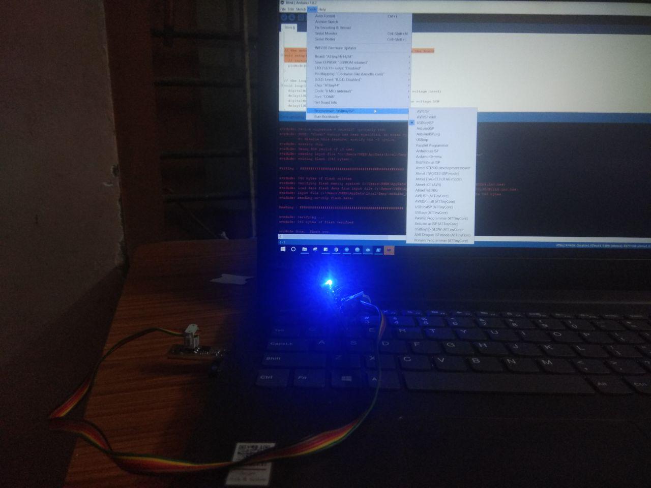
My Isp programming the Attiny44 board,
This work by Aby Michael is licensed under a Creative Commons Attribution-NonCommercial-ShareAlike 4.0 International License.
