Objectives
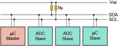
Inter - Integrated Circuit Serial Protocol
Initiate Communication
Generate Clock
Terminate Communication
Follow Master
I decided to take my Atmega 328P board from Input Week to be the master.
And take the new Attiny44 board for my final project ( See Details) as the Slave.
The boards must be programmed individually and then connected to each other to verify that one of the boards is receiving and the other to be sent.
Different Steps of the Journey
Communicating with LEDATiny as master, Atmega 328P as Slave and vice versa
Assignment 1
I decided to use LEDs on both boards to know they are transferring and recieving the data
For programming the I2C communication, i used the additional AVR library Wire.h
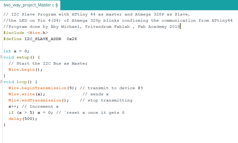
The Master code for the Atmega 328p is below
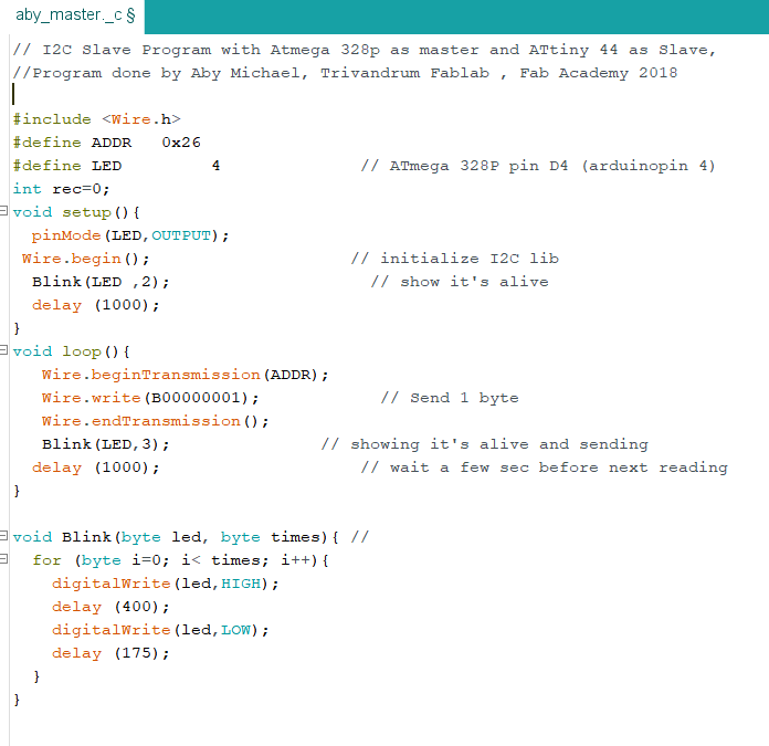
Subsequently, queue bytes for transmission with the write() function and transmit them by calling endTransmission().
or queues bytes for transmission from a master to slave device (in-between calls to beginTransmission() and endTransmission()).
LED is on D4 pin of Atmega 328P
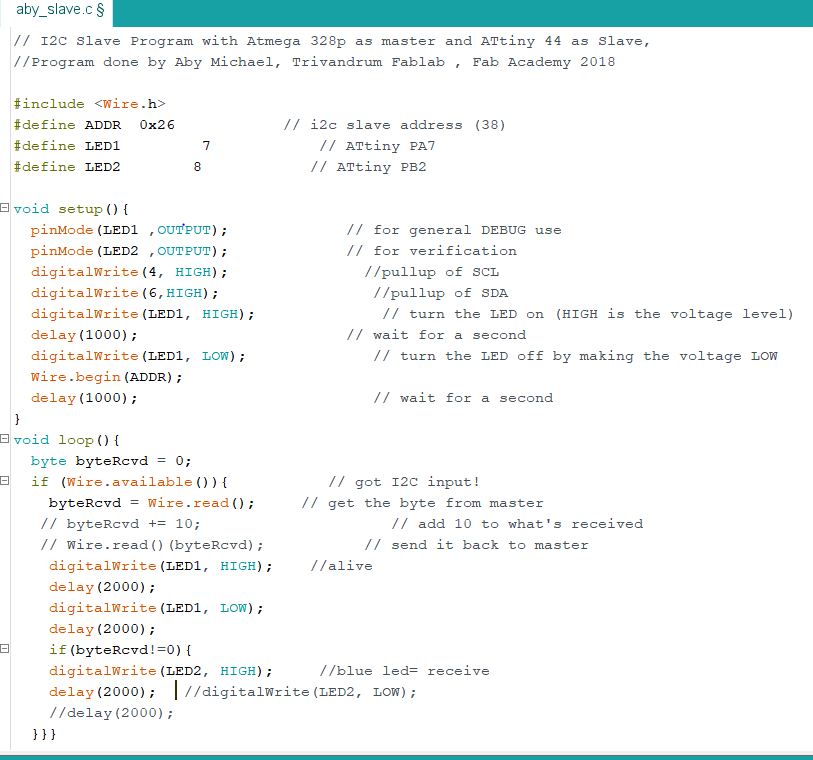
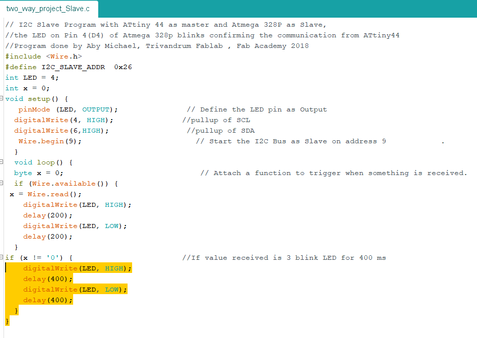
The Slave Code for Attiny 44 board is below
Download Program Files Click Here
LED1 on PA7 and LED2 on PA6 of Attiny 44 Board
Connecting the boards
I made a picture representing all the wires involving my board connections to make things simpler, see below image
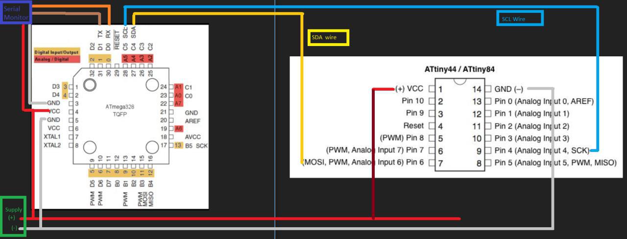
The SCL and SDA pins of Atmega 328p are A5 and A4 pins whereas the SCL and SDa pins of ATtiny 44 are Pins 4 and 6 (SCK and MOSI pins).
There should be VCC and GND connections to both boards.
I have shown the serial monitor connection to the master for my next assignments to give and take readings from the boards( connecting servo and PIR sensor )
See below video showing my boards communicating
Assignment 2
I decided to make ATtiny 44 as the master and Atmega 328p as the slave. It was quite easynow as
The Master code for the Atmega 328p is below
The Slave Code for Attiny 44 board is below
Download File Click Here
See below video showing my boards communicating
This one shows Attiny 44 as master and Atmega 328P as Slave
This work by Aby Michael is licensed under a Creative Commons Attribution-NonCommercial-ShareAlike 4.0 International License.
