Objectives
MIT App Inventor 2
Switching on and off the LED in the ATtiny44 board , using bluetooth module inteface using Androind Application.
See the Design for the App
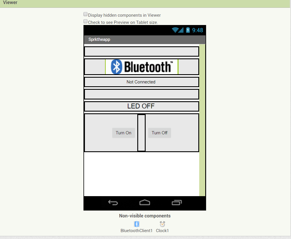
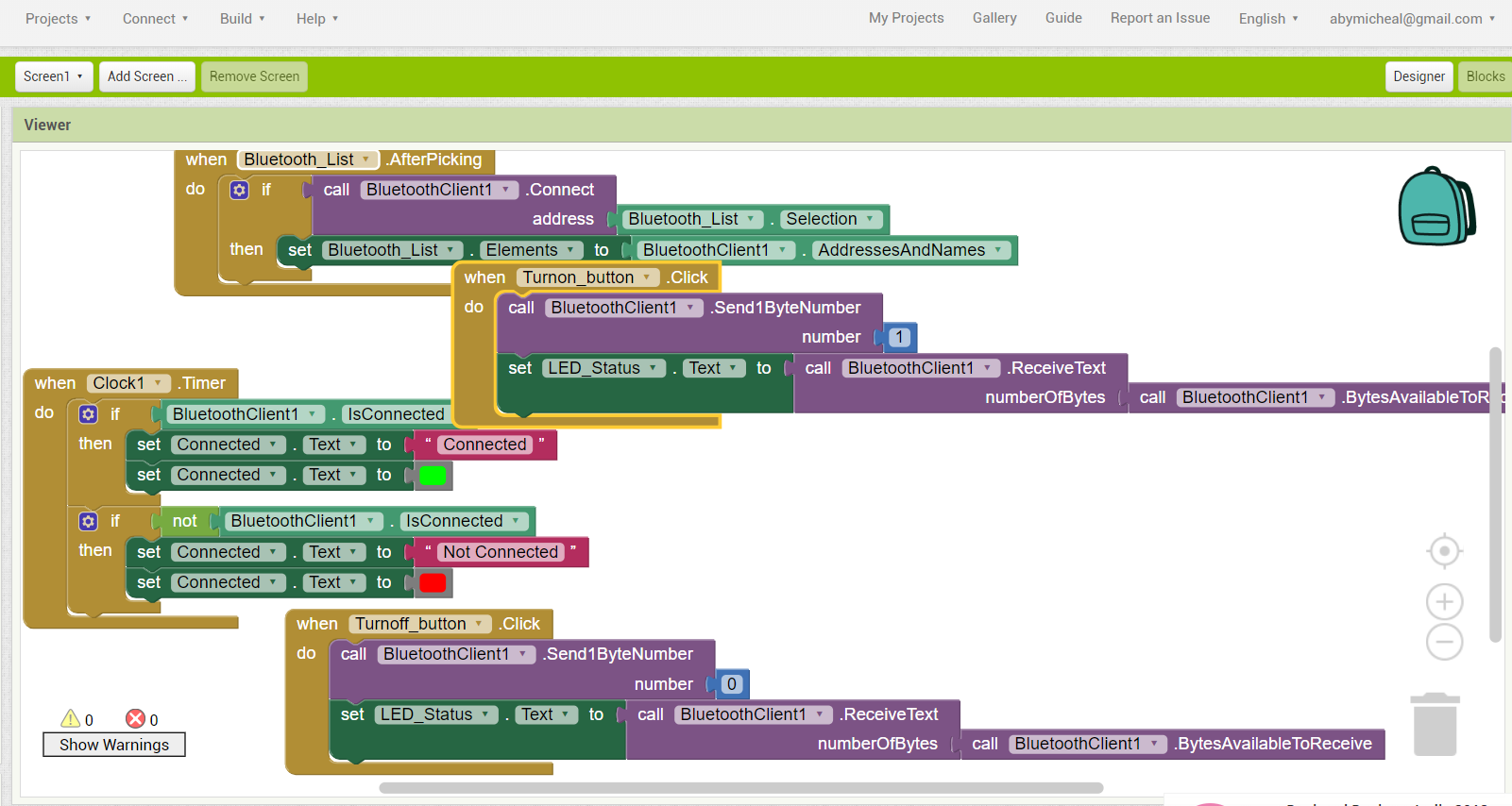
See the Block fucntions
Design the board
I have designed a board with ATtiny44 microcontroller with pins allocated for the motors, bluetooth and the Sensors. Designing was done on the Eagle software and see below the schematic diagram.
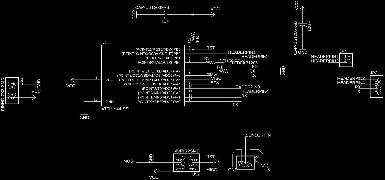
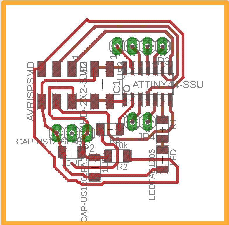
See below the Board view.
to Download the Design Files Click Here
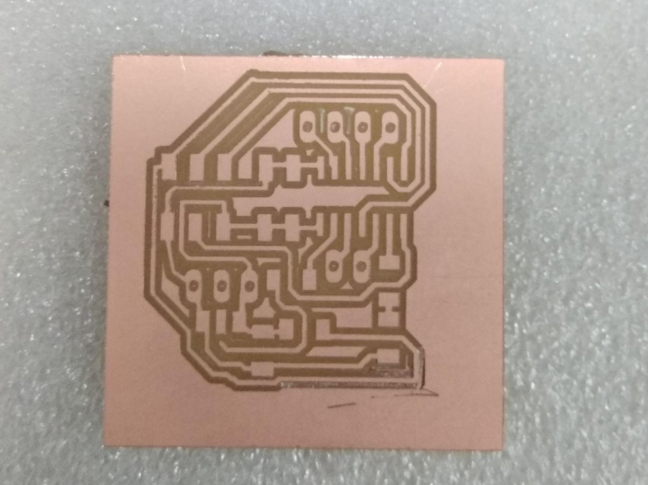
Milling the board
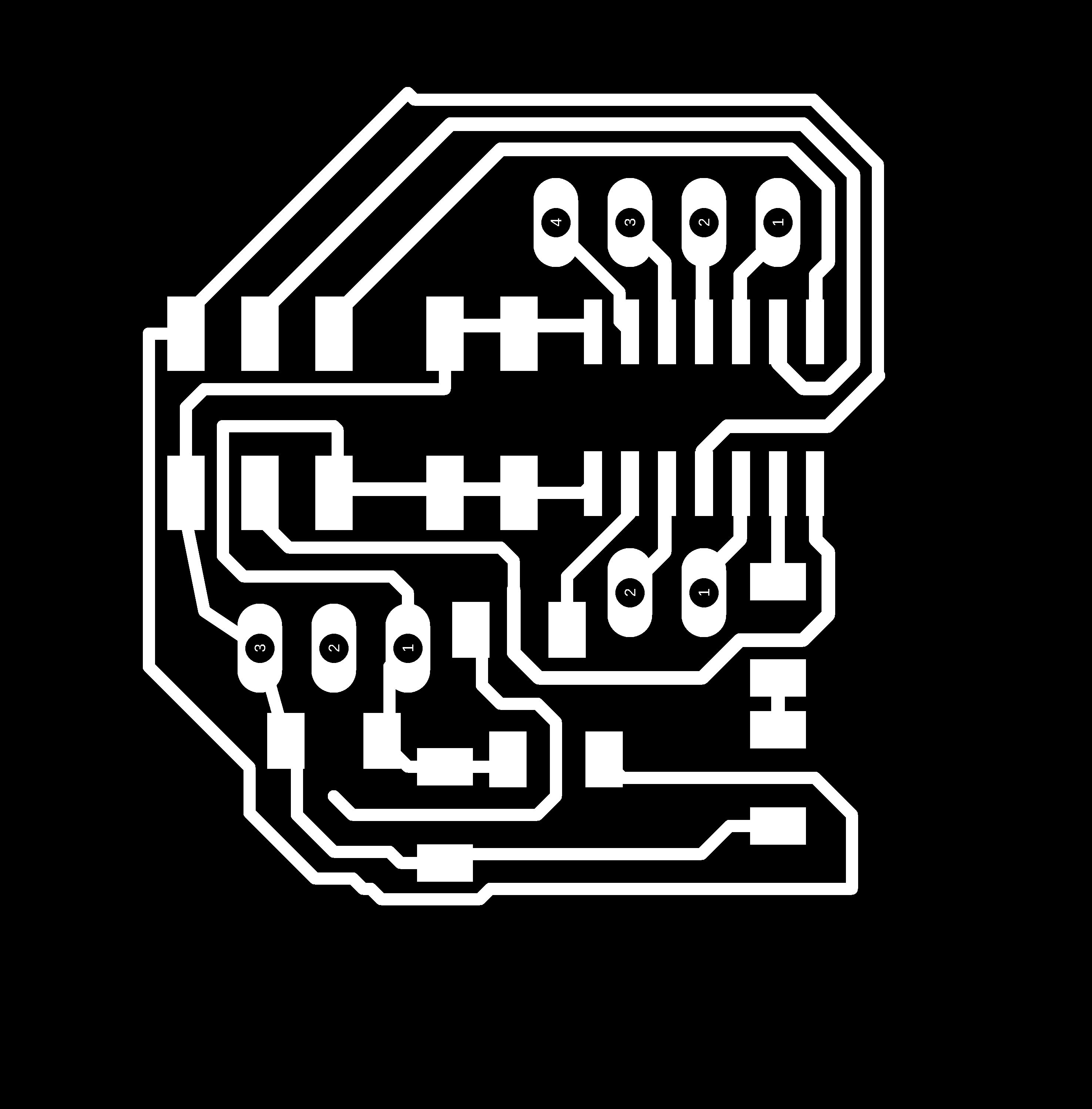
The trace image

The cut image
to Download the Mill Files Click Here
The board was ready and it is working , See below image
The board before soldering
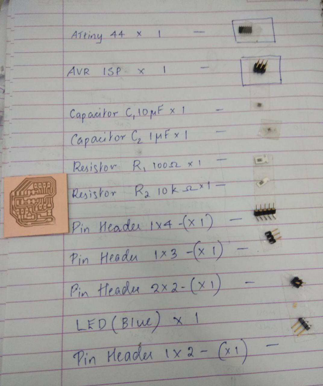
The list of components used in making the board
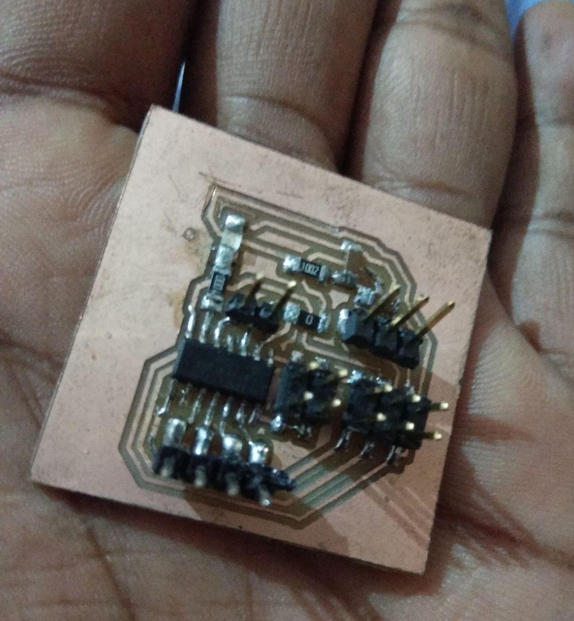
The finished board
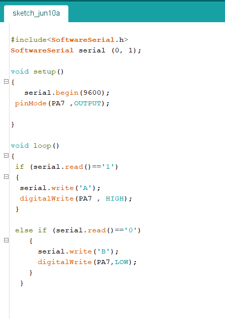
Arduino Program for MIT app Inventor 2
I have done the programming for the ATtiny 44 board which i milled for my Final Project. Click Here
Arduino pin 5 of Attiny44 is connected to LED
Bluetooth module HC-05
I bought a Bluetooth module HC-05 from online.
Data sheet of HC-05 Bluetooth Module
HC-05 Technical Specifications
- Serial Bluetooth module for Arduino and other microcontrollers
- Operating Voltage: 4V to 6V (Typically +5V)
- Operating Current: 30mA
- Range: <100m
- Works with Serial communication (USART) and TTL compatible
- Follows IEEE 802.15.1 standardized protocol
- Uses Frequency-Hopping Spread spectrum (FHSS)
- Can operate in Master, Slave or Master/Slave mode
- Can be easily interfaced with Laptop or Mobile phones with Bluetooth
- Supported baud rate: 9600,19200,38400,57600,115200,230400,460800.
Enable / Key - This pin is used to toggle between Data Mode (set low) and AT command mode (set high). By default it is in Data mode
Vcc - Powers the module. Connect to +5V Supply voltage
Ground - Ground pin of module
TX -Transmitter -Transmits Serial Data. Everything received via Bluetooth will be given out by this pin as serial data.
RX - Receiver - Receive Serial Data. Every serial data given to this pin will be broadcasted via Bluetooth
State - The state pin is connected to on board LED, it can be used as a feedback to check if Bluetooth is working properly.
LED - Indicates the status of Module
Interfacing
I have done the programming for the ATtiny 44 board which i milled for my Final Project, Click Here for More Details of the Board
The bluetooth module RX to Tx and TX to RX of the microcontroller board.
GND and Vcc to GND and Vcc of board
I connected the the LED was connected to arduino pin 7
This work by Aby Michael is licensed under a Creative Commons Attribution-NonCommercial-ShareAlike 4.0 International License.
