Objectives
Output Devices
Liquid Crystal Display
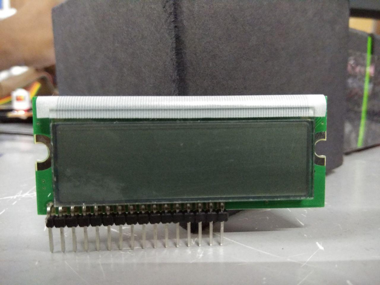
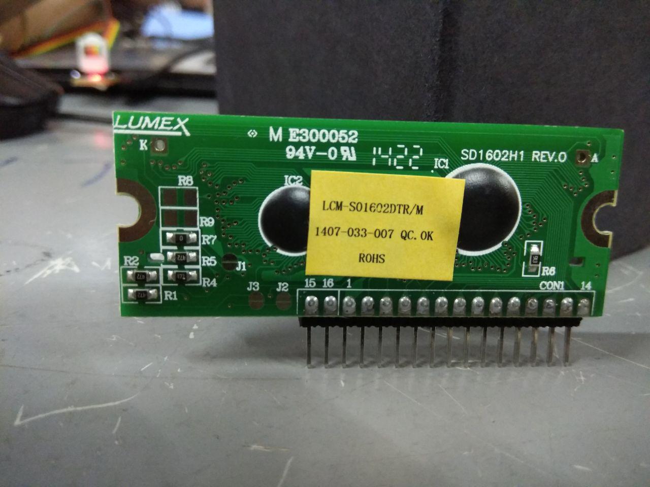
LCD (Liquid Crystal Display) screen is an electronic display module and find a wide range of applications. A 16x2 LCD display is very basic module and is very commonly used in various devices and circuits. These modules are preferred over seven segments and other multi segment LEDs. The reasons being: LCDs are economical; easily programmable; have no limitation of displaying special & even custom characters (unlike in seven segments), animations and so on.
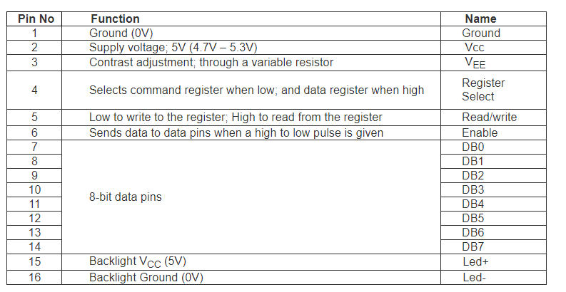
A 16x2 LCD means it can display 16 characters per line and there are 2 such lines. In this LCD each character is displayed in 5x7 pixel matrix. This LCD has two registers, namely, Command and Data.
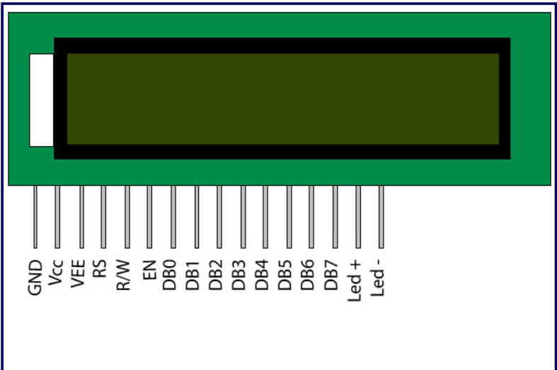
The command register stores the command instructions given to the LCD. A command is an instruction given to LCD to do a predefined task like initializing it, clearing its screen, setting the cursor position, controlling display etc. The data register stores the data to be displayed on the LCD. The data is the ASCII value of the character to be displayed on the LCD.
Servo Motor
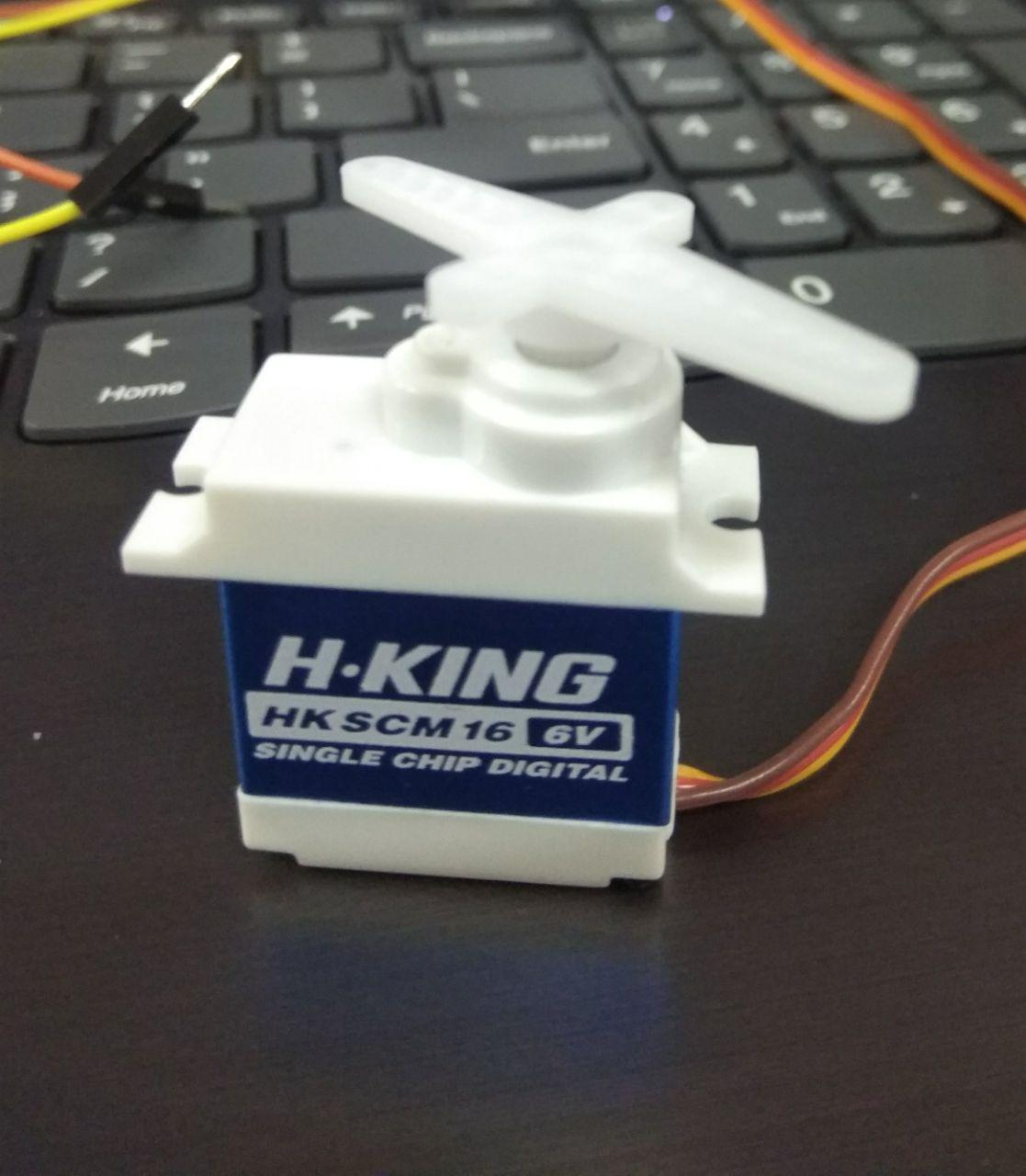
Servo Motor
Please see the manufacturer product page of the servo we used Click HereA servomotor is a rotary actuator or linear actuator that allows for precise control of angular or linear position, velocity and acceleration. It consists of a suitable motor coupled to a sensor for position feedback. It also requires a relatively sophisticated controller, often a dedicated module designed specifically for use with servomotors.
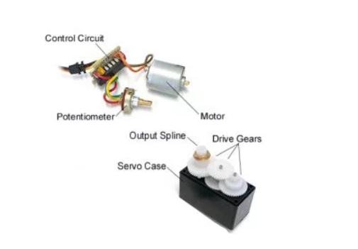
Whats inside Servo
A small DC motor, potentiometer, and a control circuit. The motor is attached by gears to the control wheel. As the motor rotates, the potentiometer's resistance changes, so the control circuit can precisely regulate how much movement there is and in which direction.
When the shaft of the motor is at the desired position, power supplied to the motor is stopped. If not, the motor is turned in the appropriate direction. The desired position is sent via electrical pulses through the signal wire. The motor's speed is proportional to the difference between its actual position and desired position. So if the motor is near the desired position, it will turn slowly, otherwise it will turn fast. This is called proportional control. This means the motor will only run as hard as necessary to accomplish the task at hand, a very efficient little device.
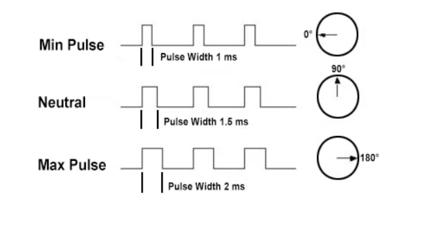
Servos are controlled by sending an electrical pulse of variable width, or pulse width modulation (PWM), through the control wire. There is a minimum pulse, a maximum pulse, and a repetition rate. A servo motor can usually only turn 90° in either direction for a total of 180° movement. The motor's neutral position is defined as the position where the servo has the same amount of potential rotation in the both the clockwise or counter-clockwise direction. The PWM sent to the motor determines position of the shaft, and based on the duration of the pulse sent via the control wire; the rotor will turn to the desired position. The servo motor expects to see a pulse every 20 milliseconds (ms) and the length of the pulse will determine how far the motor turns.
When these servos are commanded to move, they will move to the position and hold that position. If an external force pushes against the servo while the servo is holding a position, the servo will resist from moving out of that position. The maximum amount of force the servo can exert is called the torque rating of the servo. Servos will not hold their position forever though; the position pulse must be repeated to instruct the servo to stay in position.
Designing the Board
I have planned to make a board with Servo driver and Liquid Crystal Display.
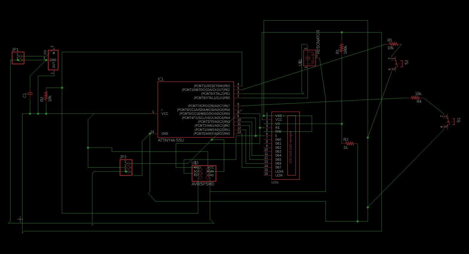
Designing on Eagle
I thought after all these weeks of electronics i have improved in my PCB designing. But gone wrong (i found this out only later when i was soldering) this time too, I had to use 7 jumpers to make my board work, too shameful for me. I have explained about it in detail in the troubleshooting part after soldering.
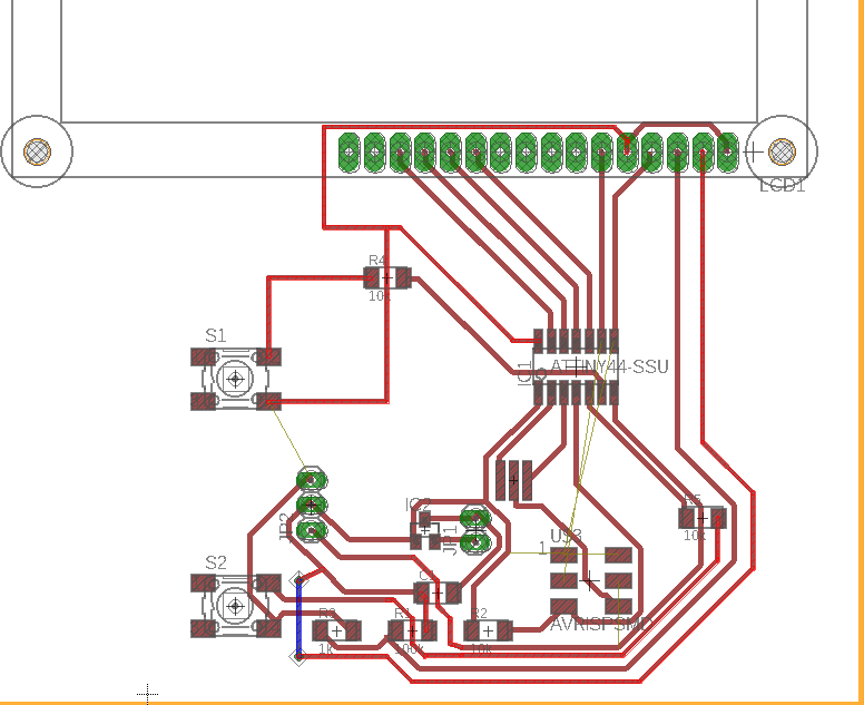
So coming back to my PCB designing, I was actually planning to combine Neil's Servo board and LCD board together. I have become now faster in drawing the schematic and making the board, see below my schematic diagram
See below for my Board design.
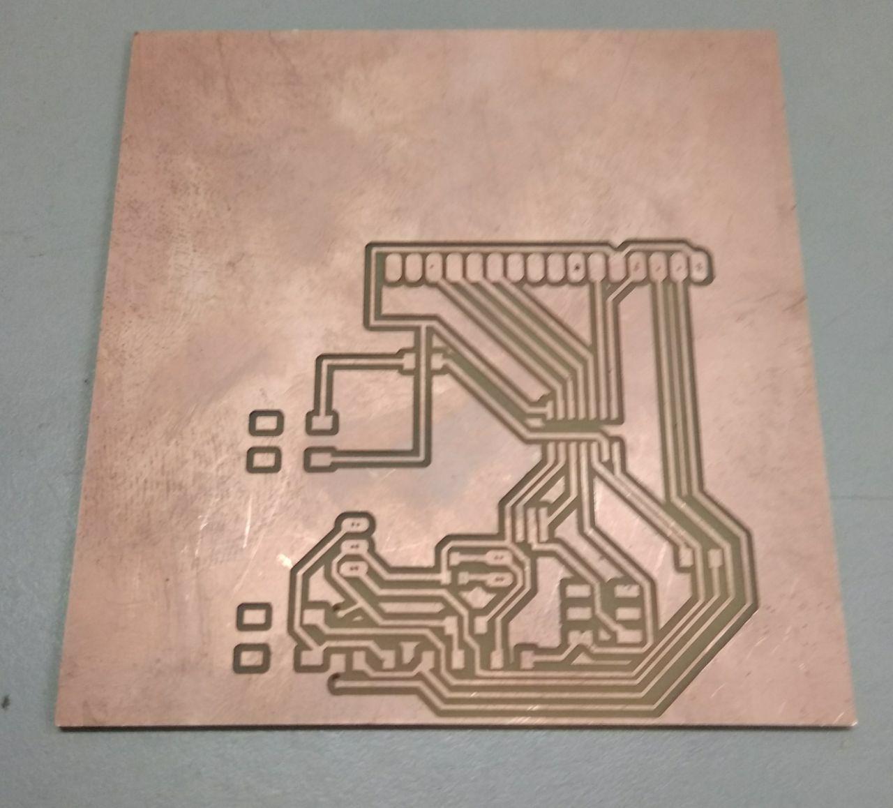
Milling the board
I used the 1/64 tool bit for the traces
See the Miling files - Download Milling Files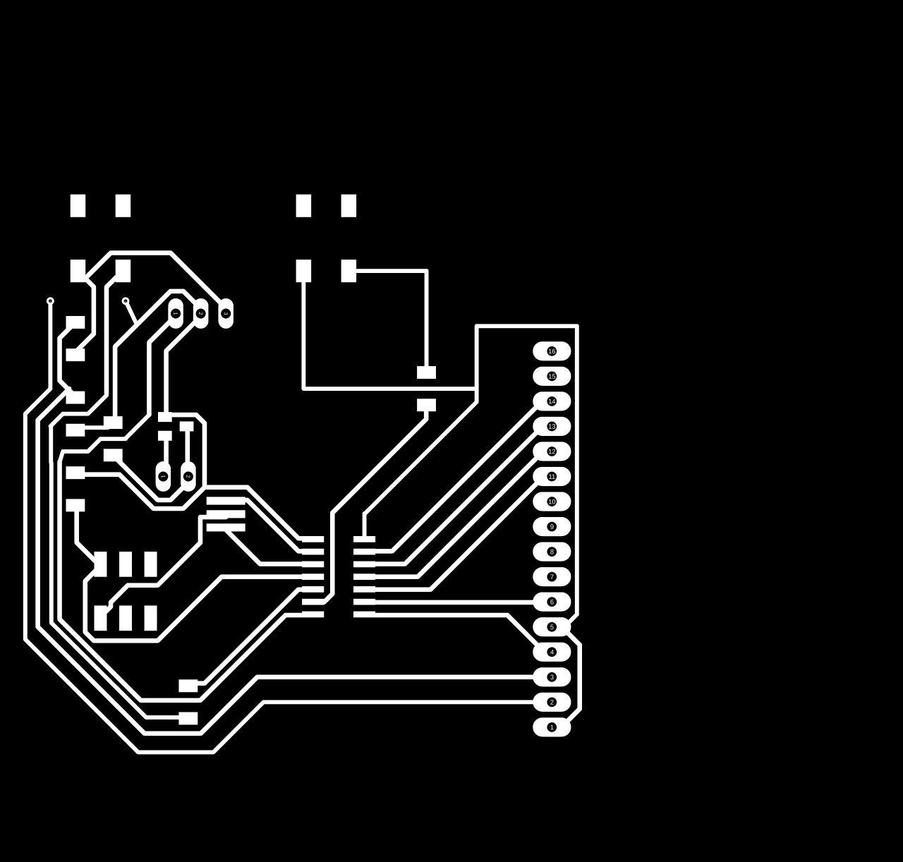
I used the 1/32 tool bit for cuts and drills


The mill was fine
See the Miling files - Download Milling Files
Soldering and Troubleshooting
During my soldering I noticed that I forgot to connect the MISO, MOSI, SCK and GND pins of AVR ISP to that of Attiny44,
See below corrected design
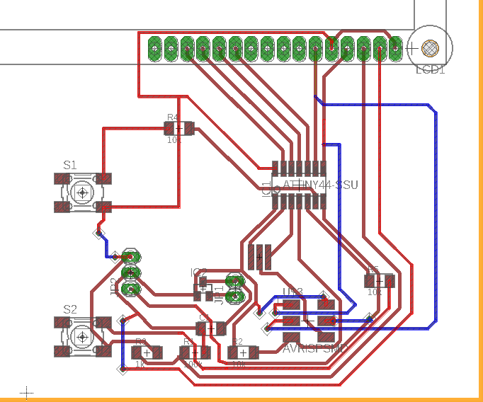
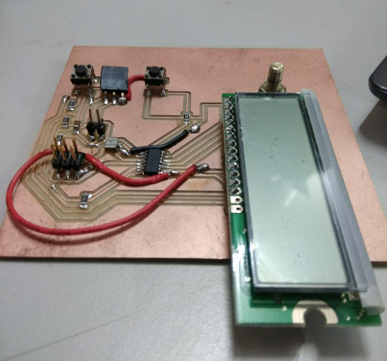
The below one is the board with jumpers
Programming
Liquid Crystal Display as Output Device
The connections which are done for LCD are given below:
First I tried the program to display any message on LCD screen
See below video of my board displaying my Name and Fablab Kerala name
Download File Download Program FileServo Motor as Output Device
The connections wto the servo are
I tried making the servo work with my program
See below video of board rotating the servo motor
Download File Download Program FileGroup Assignment
to Measure the power consumption of an output device
Dc motors are not connected directly to microcontroller boards, we use Motor drivers to connect it with a microcontroller.
The motors require a relatively higher voltage and current, to supply this current we require the motor driver IC.
We used L239D motor driver module to control small Dc motor.
L239D motor driver is a small Current Amplifier whose function is to take a low-current control signal and then turn it into a higher-current signal that can drive a motor
Motor need large amount of energy, cheap and local motors it goes high
Voltage Requirement : Here we used motor is only run at voltage between 8v to 12 V
Current : Normally L239D can supply current of 1.2 Amphere , so peak to peak become almost 3A, if we need more current we have to provide heat sink over the driver IC
This work by Aby Michael is licensed under a Creative Commons Attribution-NonCommercial-ShareAlike 4.0 International License.
