
In this week we have to programme the board that we made in the week of "electronics design" .Here we added an LED & Switch to board and also flashed with the ISP programmer that we made in "week 5" .In this we had to learn how programming the chip and here we make some different programme for the LED & Switch using some programme languages.
ATtiny44 and Data sheet
ATtiny44 is 8-bit AVR microcontroller. These are modified Harvard architcture so the flow of data through CPU is in high speed and this is known as Advanced RISC Architecture (REDUCED INSTRUCTION SET COMPUTING).In RISC architecture simple instructions are exicuting with in a single clock cycle
It has a non violate memory segment here the memories are devided into 2k/4k/8k bites and these are self programmable
Pin configuration & Block Diagram.
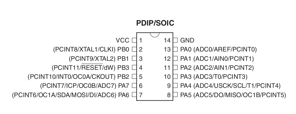 pinout of Atiny44A/24A/84A
There is always an identification mark that will help to count the pin
easly from the first also can identify the corecct orientation of the pin
VCC:vcc is the supply of voltage
GND: Ground
Port B:PB0 TO PB3 are called portB here 4 port are there in "B"
Port A:PA0 TO PA7 are called PortA here 8 port are there in "A"
ADC : analog to digital convertor
PCINT : The pin can be used for interupt operations
RESET:This pin is used as RESET (the line above the RESET shows "active low" to active the pin we have to pull the pin low)
XTAL:This pin can be used as the external clock so we can connect oscillator to this pin
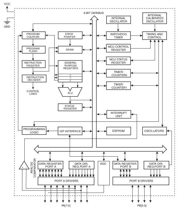 Block diagramme
The AVR core combines a rich instruction set with 32 general purpose working registers. All 32 registers are directly connected to the Arithmetic Logic Unit (ALU), allowing two independent registers to be accessed in one single instruction executed in one clock cycle. The resulting architecture is more code efficient while achieving throughputs up to ten times faster than con- ventional CISC microcontrollers (Complex Instruction set Computing).CISC has the capacity to perfome multi-step operation or adressing mode with in one instruction.
Here a 8bit /16bit timer with two PWM channels(Puls Width Modulation or PWM means the modulation techniqe used to encode a massage into pulsing signals) and also its has a programmable watchdog timmer with internal oscillator and internal calibrated oscillator.IDEL mode(The certain amount of time taken by the CPU for running a task on the computer system) stops the CPU while allowing the SRAM(Statcic Random Access Memory that uses to store each bit means the data remains after erase)
Reading EEPROM
1.When system clock frequency is below 900kHz ,The microcontroller can't read limite no of signals this
signals is known as EEprom signals(Electrically Erasable Programmable Read-Only Memory).Here This can be Avoid using the
EEPROM at clock frequency below 900 kHz .
2.When the Memory Lock Bits LB2 and LB1 are programmed to mode 3, EEPROM read does
not work from the application code.here also avoid setting Lock Bit Protection Mode 3 when the application code needs to read from
EEPROM.
Programming of the board
C programming language is a statement that was designed to be compiled using a compiler .Avr-gcc is a compiler that takes c language high level codes and create a binary source which can be uploaded into a Avr microcontroller.Here for running the programme into the bord we want to generate a HEX format file,the hex file can flash to bord using programmer
Here I used to language software "C" and "Arduino IDE". I firtsly tried "C" for applying delay to the Board so I write the programme on atom and saved it as .c file
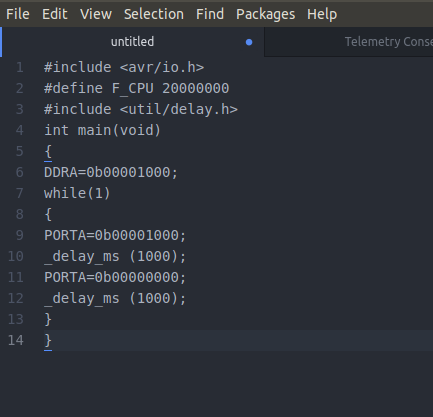
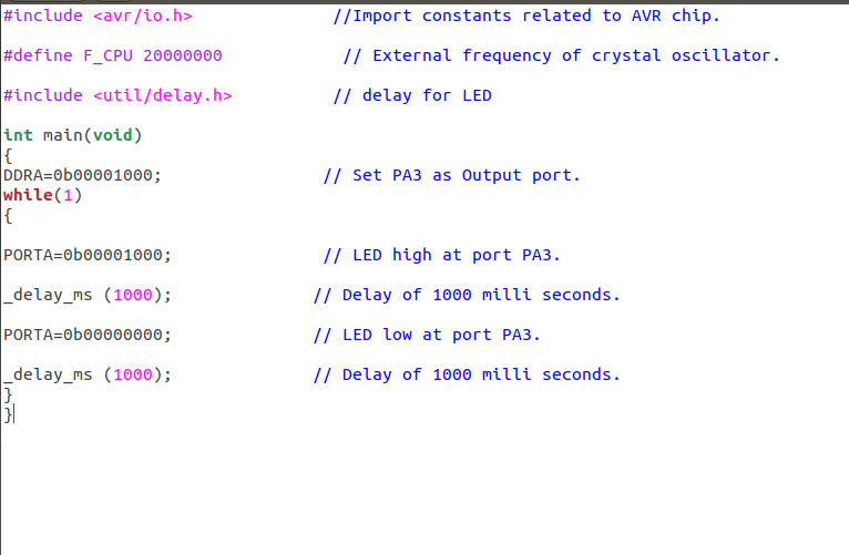 codes and its mention
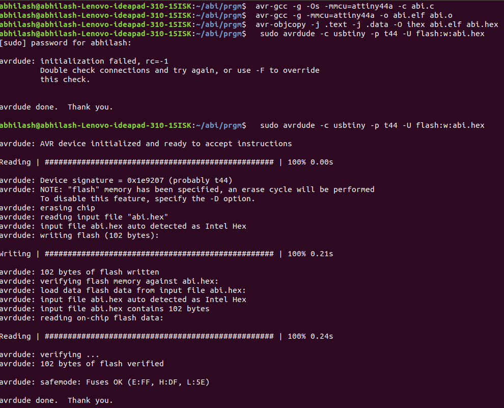
After Saving as .C file the I converted this file as .hex file by running several commands in terminal given below
  avr-gcc -g -Os -mmcu=attiny44a -c filname.c

    avr-gcc -g -mmcu=attiny44a -o filename.elf filename.o

    avr-objcopy -j .text -j .data -O ihex filename.elf filename.hex

    sudo avrdude -c usbtiny -p t44 -U flash:w:filename.hex

Then I flashed .hex file into the board and the working video of my board is below
programming using Arduino IDE

Arduino IDE is also a Programme language here I used Arduino for for controlling the LED using the switch Arduino is an open source electronic platform based on the easy to use harware and software . its is intented for any one making intracting project.Here I also write the programmerby giving if & else
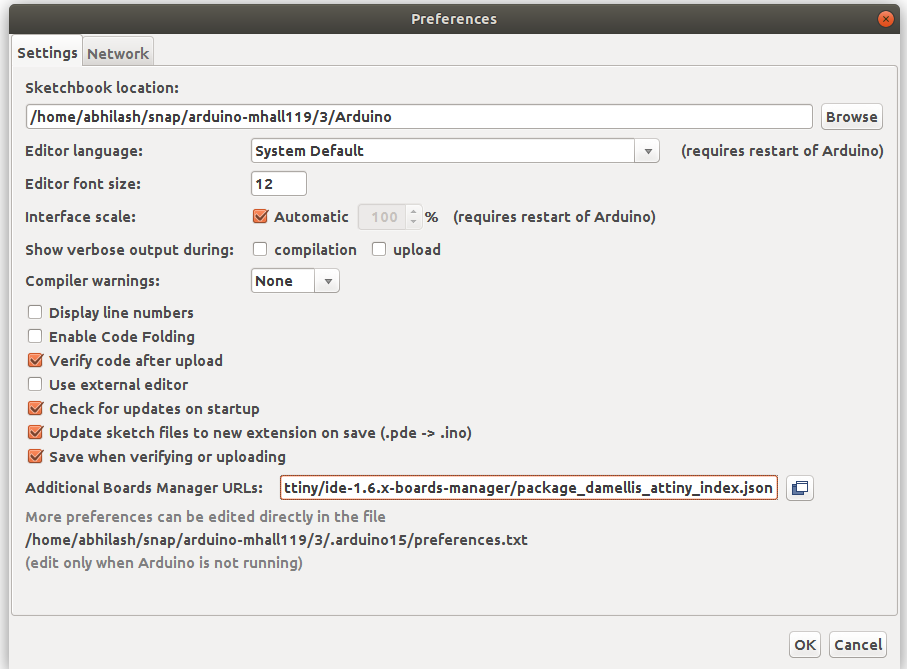
When using the Arduino language first we want to install ATtiny support using built in board manager ,so open preference in file and add the given link to the "Additional Board Manager URLs."then ok.
https://raw.githubusercontent.com/damellis/attiny/ide-1.6.x-boards-manager/package_damellis_attiny_index.json
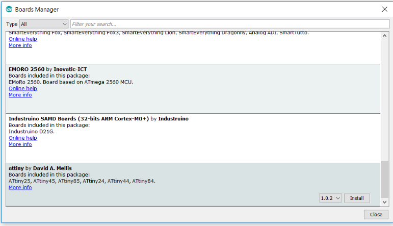
After that open Tool - clik on Board then open "board manager" here you can see ATtiny"s information we can install it into the software by install button on it
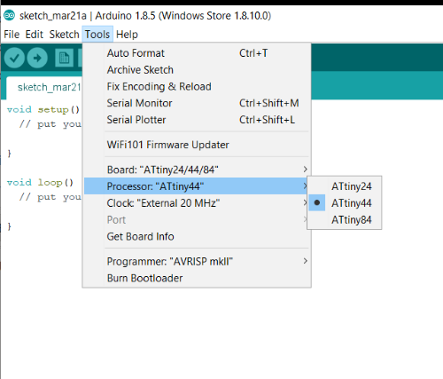
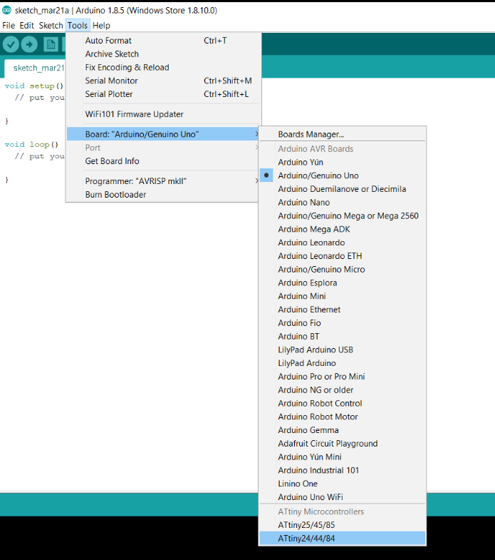 selecting the board as ATtiny44 that we installed
 Also selecting the processor and external clock that having in our board fromm the "Tool option (processor- ATtiny44 & clock -20MHz)"
Then I made a simple data for reading the input signals from the switch and giving tthe output through the LED .So I tried an attempt with On and OF using digitalwirite and read ,here is the programme that i wrote in Arduino software
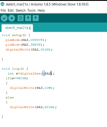
Then I verified and uploaded the programme to my board like a trial ,the working of my board is below it is simple data programme of checking input and output signals
MY REVIEW
In this week we studied more about programming I hadn't any experience with electronics and programming but the week taught something different . I tried to learn the base ,So I made simple data for programming I know this is the first step in my Fab carrier towards making electronics programme languages here I want to try more in these softwares.The week was very good to me for trying some different experience