In this week we want to show the output of a device that we programmed . In last week we learnt about Input through sensors and shows the input of different sensors through programme ,But now we want tot display the output through different medium like video,sound ,light ... Through Neil's class we got the Idea that what we want do on this week He explained all the medium that we want to display our output . In all medium there is board and programme with videos that helps us as a tutorial in this week
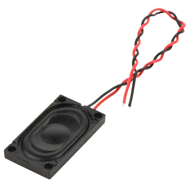
Here I selected "Speaker" as my output device in this week here I decided to take a change in my final project so to my new project one of the output is very related to speaker so I desided to take with that. Speaker is mainly a sound producing medium so my decision was to produce music through programme to show my output
This is small speaker in the series CDS-25148-L100 it has a maxium input power IEC-60268-5, filter 60s on/120s off, 10 cycles at room temp . Data sheet and more about this speaker is here .
Group Assignment
Here we need to calculate power consumption of a output device. We choose a motor to do the same. Dc motors are not connected directly to
microcontroller boards.We use Motor drivers to connect it with a microcontroller.
microprocessors operate at low voltages and require a small amount of current to operate while the motors require a relatively higher voltage and current. This current cannot supply to the
motors from the microprocessor. This is the primary need for the motor driver IC.
Here we are using L239D motor driver module to control small Dc motor.L239D motor driver is a small Current Amplifier whose function is to take a low-current control signal and then
turn it into a higher-current signal that can drive a motor.
Power the motor,
Motor need large amount of energy, cheap and local motors it goes high .
. Voltage Requirement:Here we used motor is only run at voltage between 8v to 12 V.
. Current:Norammly L239D can supply current of 1.2A , so peak to peak become 3A something.if we need to give more current we need to provide heat sink over the driver IC
1.DESIGNING OF BOARD
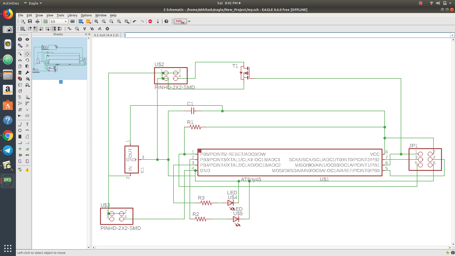
After reffering Neils board I deided to make a board by giving some changes ATtiny is limited in pins so the desingning is bit more easier that other IC ,Here I taken Eagle to the desinging for my board .Using eagle is very familiar to me so I first tried to draw schematic diagramme and the switch it into the board
Here I used ATtiny45
2*2 Header pin
2*3 Header pin
10k ohm Resistor
1mF capacitor
n mosfet SOT-23 channel
IC2 5V Regulator
LED RED & BLUE
RES 499 ohm
After desinging I switched it into the Board after arrainging it properly I give the clearence and the size to "16 mill and 18" the I just go forward with Autorout Here I got a full 100% route correctly that helps me from manual route
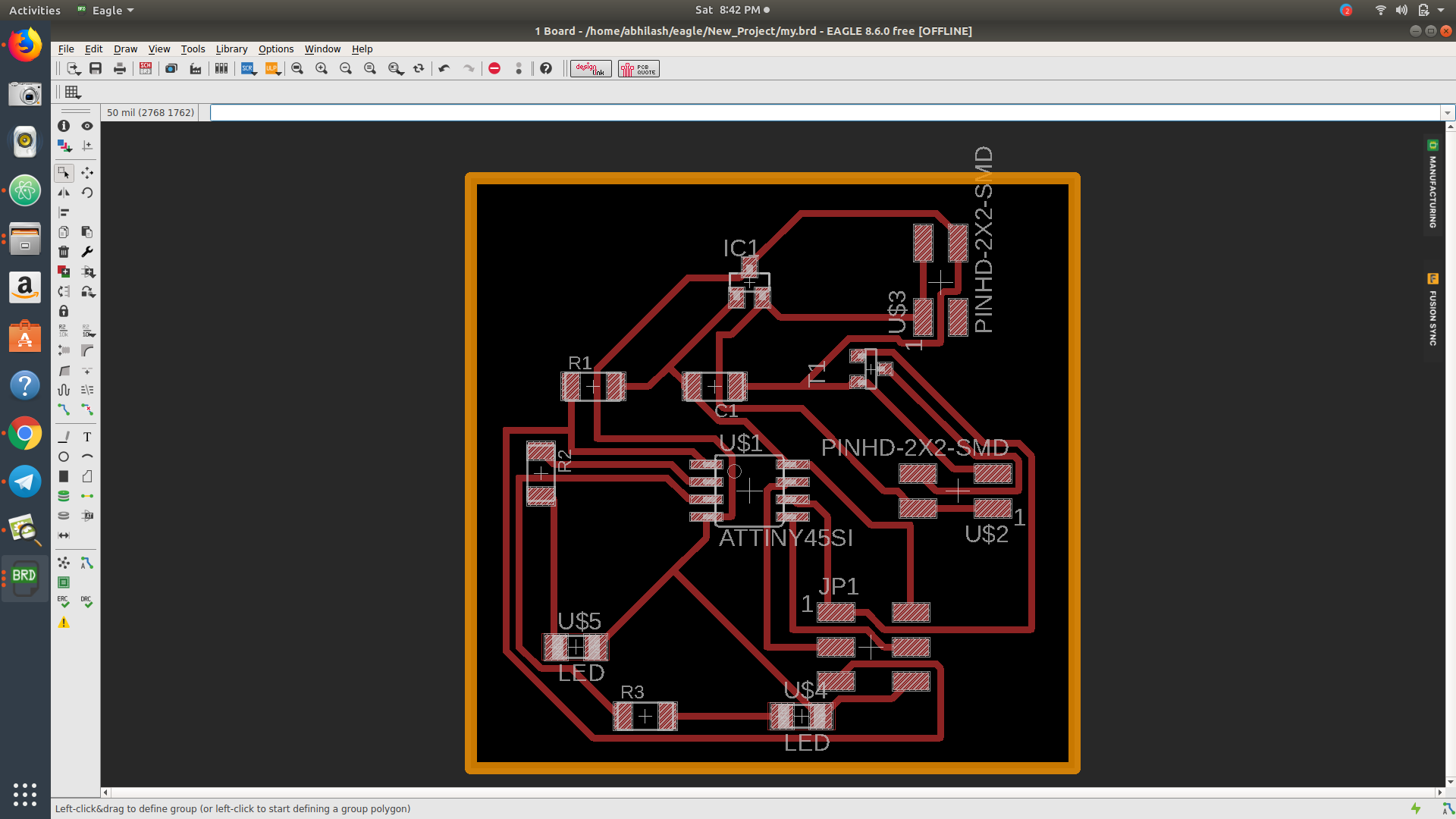
Finishing the complete desinging of the board I decided to export the board into .png file so that I selecte the milling part through layer tool by giving top and pad then exported it as.png by giving monochrome and the next cutting part through dimension (already gave the width 33 mill) by giving monochrome . you can download my board
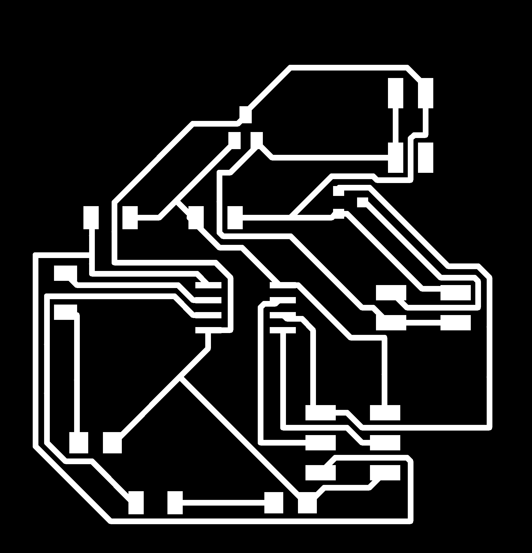
 milling and cutting part of the board
 Here is the trace.png image
Here is the cut.png image
.SCH file you can download here
.BRD file you can download here
2.MILLINING OF BOARD
In previous week also We got very familiar With the "Roland milling machine" so the operating of the machine seems very easy then I opend my image on fabmodule and also adjusted the "x,y,z" plane with 1/64 bit for milling
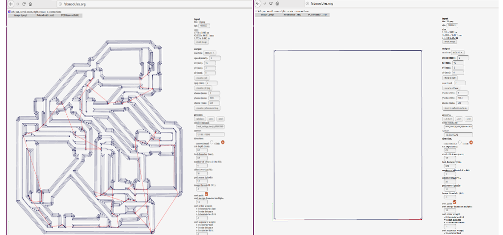 opend the .png image and giving settings
1/64 bit and 1/32 bit here I used for milling and cutting before that I adjusted the plane and speed .it gives a clear calculated bit path so I just sent it into processing and it gives a clear cut
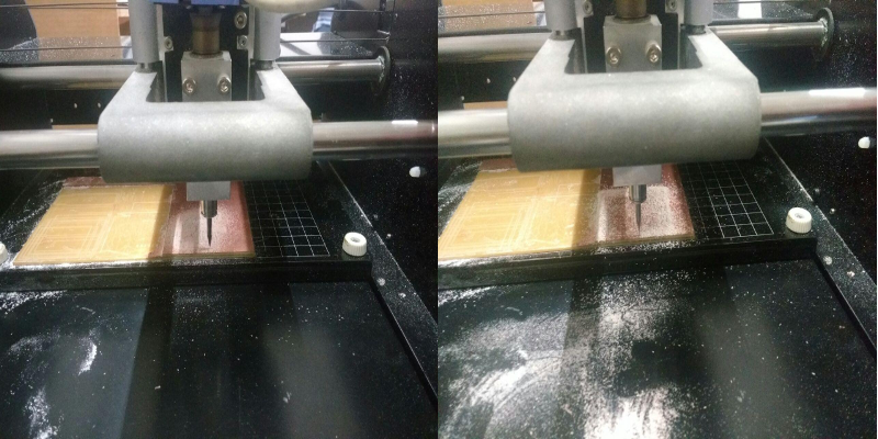 miling and cut process
Then the milling is completed I got my board but there was a place the bit couldn't make path so I decide to cut it manually ,I wasn't too difficult to me so I go forward with manually
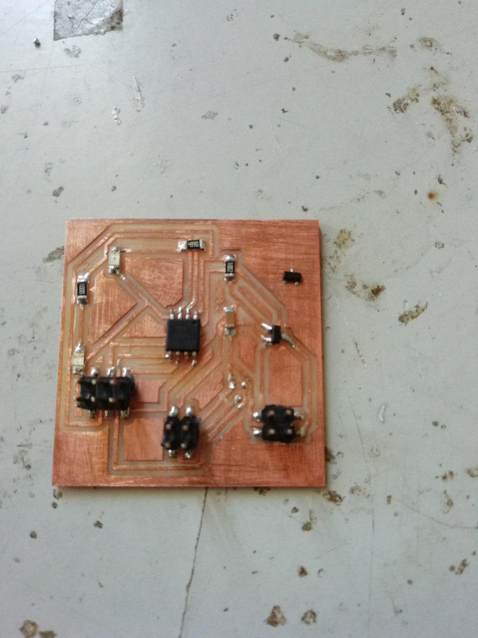
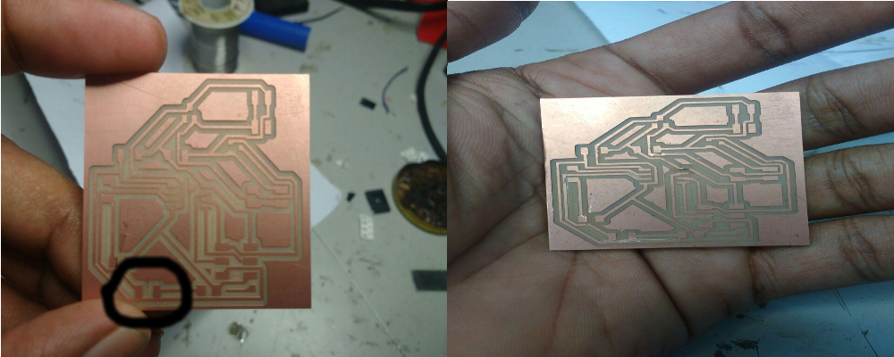 after milling / Then mannualy troubleshooted
3. SOLDERING OF BOARD
After the PCB milling Then I want solder my board ,Here I picked all the components that I want then statrted soldering Here the soldering seems much easier because we are using the soldering in contineous so It seems bit more experienced, Here I tried to solder perfectly eventhough there is not so perfect but It makes a lot of changes than earlier
components are;
ATtiny45
2*2 Header pin
2*3 Header pin
10k ohm Resistor
1mF capacitor
n mosfet SOT-23 channel
IC2 5V Regulator
LED RED & BLUE
RES 499 ohm
4. PROGRAMMING
Then I want to programme my board After soldering I just tried to find weather my IC is dictecting using this code in therminal sudo avrdude -c usbtiny -b 9600 -p t45 through "ISP" Here my board is ditecting but the connecting time with ISP "Regulator " in my board going to heating up because "when ISP is connencting to the board the current flows to the output so inside the regulator the components get heating up"
So here I used one "diod" to avoid the heating up because it will affect the life of the regulator ,Here I used "4004 diod" it can withstand 400v here doesnot want the use of 400V , here we can use higher volt DIOD than the input that's not a problem but we want to make sure that the Diod isn't below the input voltage and also notice while connecting the positive part I connected to the output of the Regulator.After using the diod the problem becomes solved then I go forward with my programme
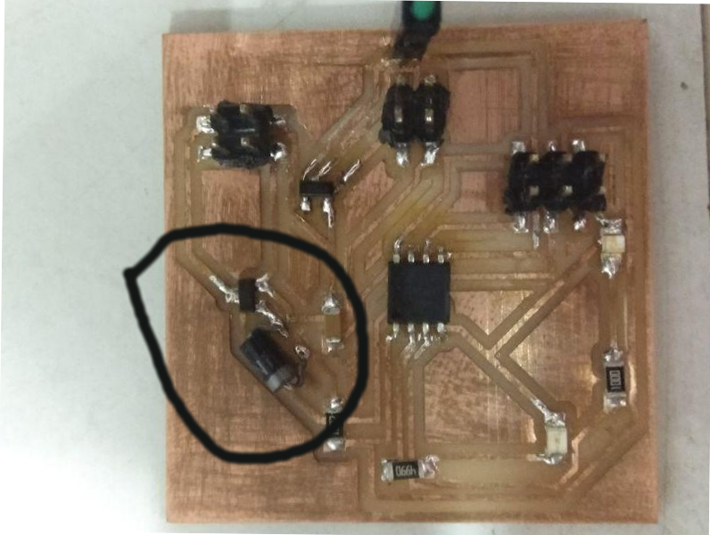 The diod positive is conencted to output of regulator
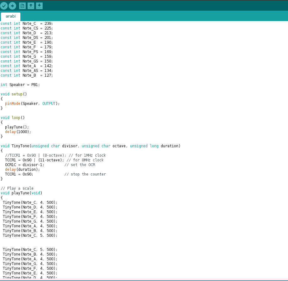
MY ARDUINO PROGRAME FOR SPEAKER
I tried Arduino for programming my board ,Here I used some "Notes " from internet and I arranged it in music manner making my speaker as output . This divides the clock frequency, which is either 1MHz or 8MHz, here the tiny tones work for this frequency then I adjusted the delay for 1000 millisecond and here you can download my programme
After making the the programme the first I compiled it the I uploaded it into my board ,there I got a fine flash through ARDUINO and then I also looked weather my Regulator is heating but through that Diod connection ,then I tried to show my output using speaker
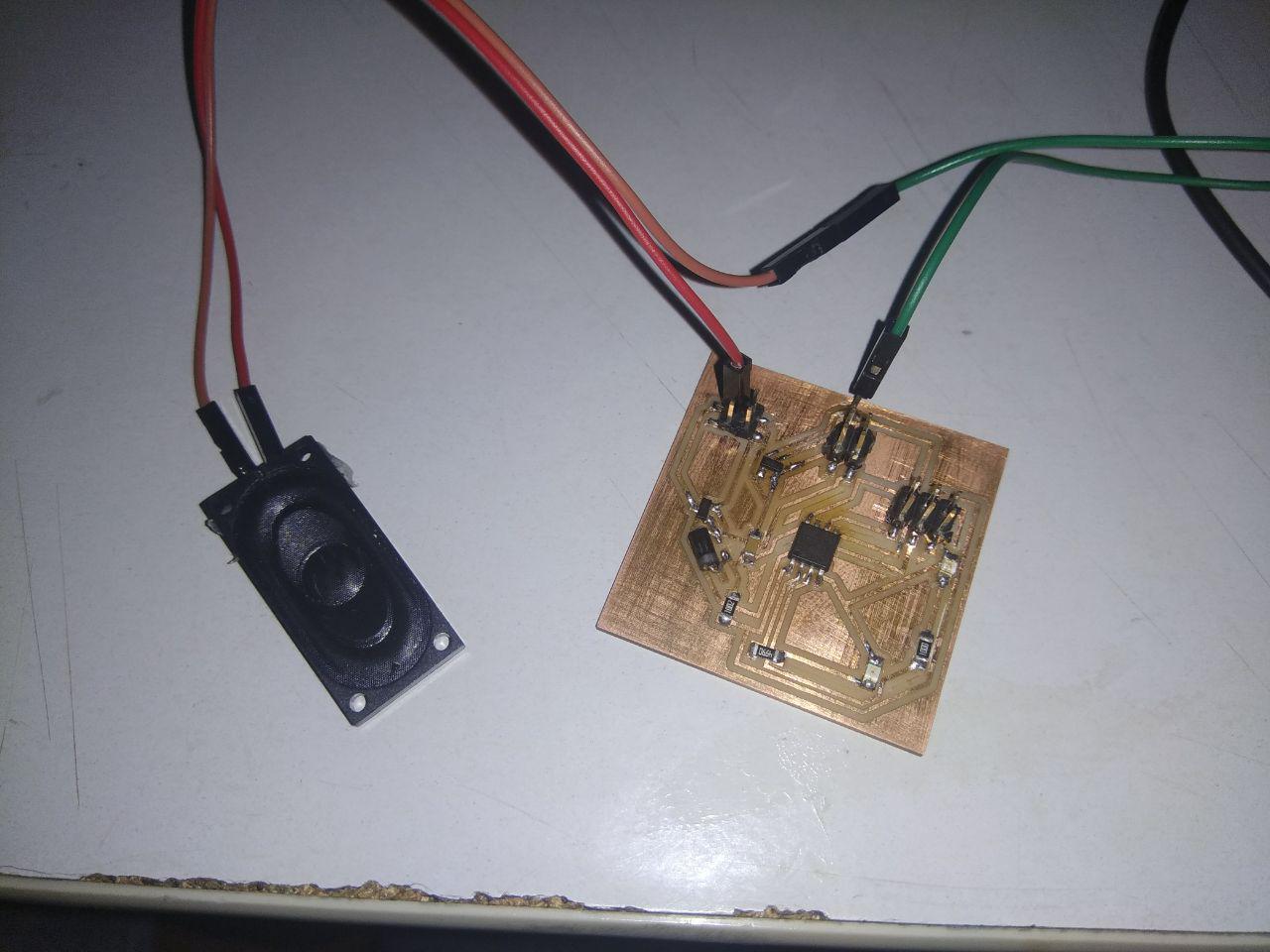
WORKING OF MY SPEAKER
Here I gave the connection through ISP to show my board's working at the time i didn't get the out put through the pins the I checked my board with multimeter then I fecthed the complaint that my mosfet didnt work properly before changing that mosfet here I showed my output through connecting the input of the speaker direct to the pin "PB1 of ATtiny 45"
PROBLEM FACED
After complete programming I was ready to show my output but I didn't get that properly at that time I stucked there I crosschecked my components with multimeter but there wasn't any problem with components then I checked it very keenly at that time in my board the I got my out put from PB1 but it will not coming to the out put pin .
There will be any voltage coming to the pins through mosfet so for the week assignment I solder the input of the speeker to PB1 but here I want to find out what was the real problem I am sure that there is no problem with my desing and soldering so I want fix this problem with the help of my instructors