This week assignment was to make a wired or wireless communication between two or more microcontrollers that is the data transmitting and receiving between two IC . The communication only happens if there is a transmitter and receiver in both ,This type of communication is known ass embadded communication This type of communication can one direction or both directions
There are many different forms of digital communicating protocoles and they are differs based on the application .Here In my week assignment I go forward with Communicating between two Arduino boards using I2C bus .I2C and SPI are small protocoles with transmitting rate upto 100/1000 mbits/s.
1. I2C communicating protocol
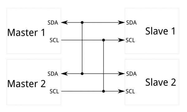
I2C or I-SQUARE-C is stands for inter intagrated circuit and allows communication of data between micro-controller and peripheral unit over two wires. Here we can divide the devices into "MASTER" & "SLAVE" the master host the communication mode we can connenct multiple board to the master with two wires
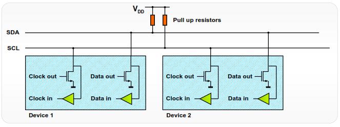
I2C bus which constituted with two data line SDL- serial data line and a SCL- serial clock line,"SDA & SCL" are with which microcontroller and controlled IC, and IC are able to communicate bidirectional at the data transmission rate up to 100kb/s. The master is connecting to the slave through the port "SDA & SCL" from a micro-controller you can read more about the I2C protocole in here
2. Board used
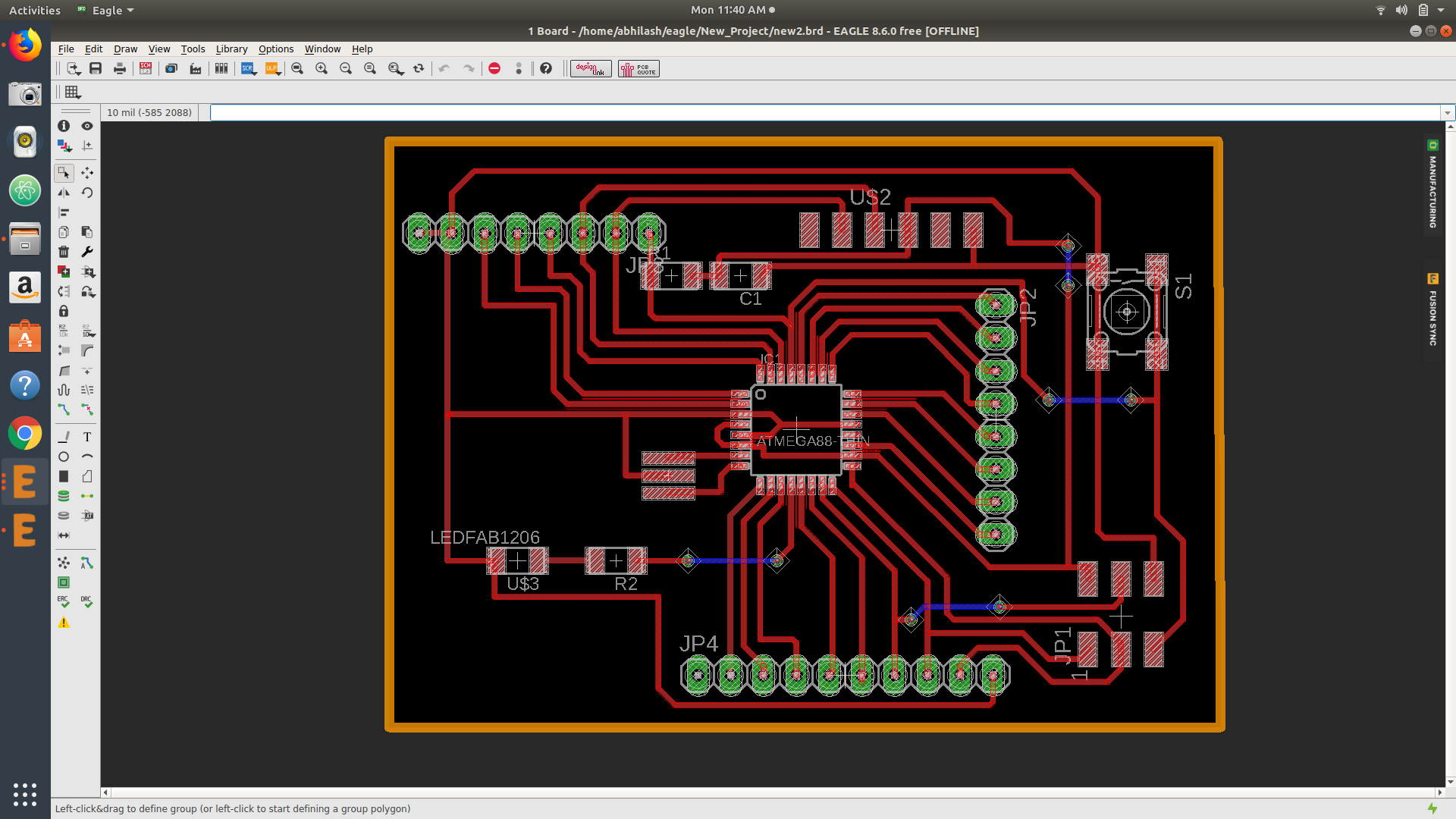
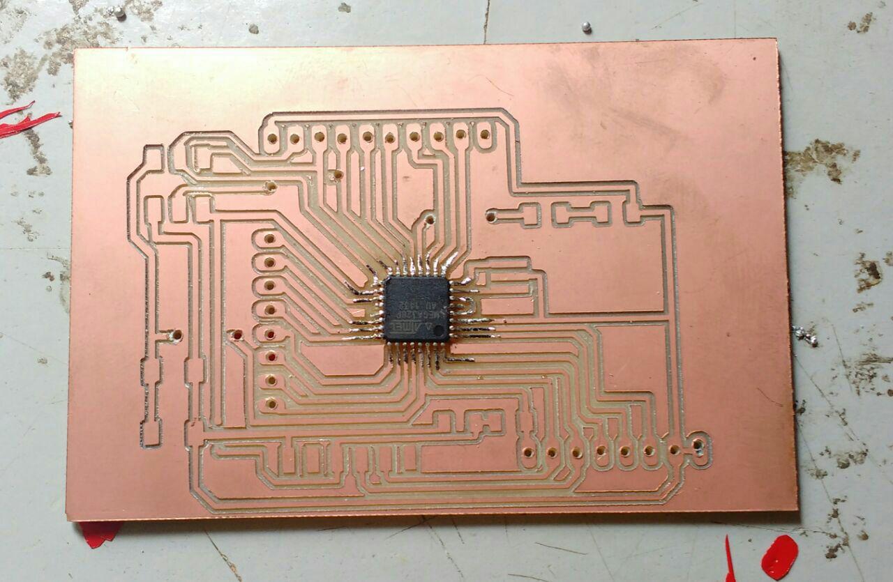
At first I decided to go forward with the two board that I made in the previous week hello word board and the board that I made in the output week but after getting some ideas from the Instructors I decided to mill one board with Atmega microcontroller It also help me for the future project so I began draw one board at eagle software ,
It very difficult were designing with Atmega I faced all the problems but most of
I tried with manual routing it takes more time for the designing but I think it save my time from the project weeks
I take out maximum pins from the microcontoller that was my aim ,not only the project I can use this board in future also
My components are;
1.ATmega328p
2.8mhz Resonator
3.LED & 499 ohm Resistor
4.FTDI & SMD header
5.1mf capacitor & 10k resistor
6.Omron switch and pin headers (2*4 & 2*5)
After drawing I Exported the board the file by selecting top & pad for trace and dimension for cut and vias for drilling
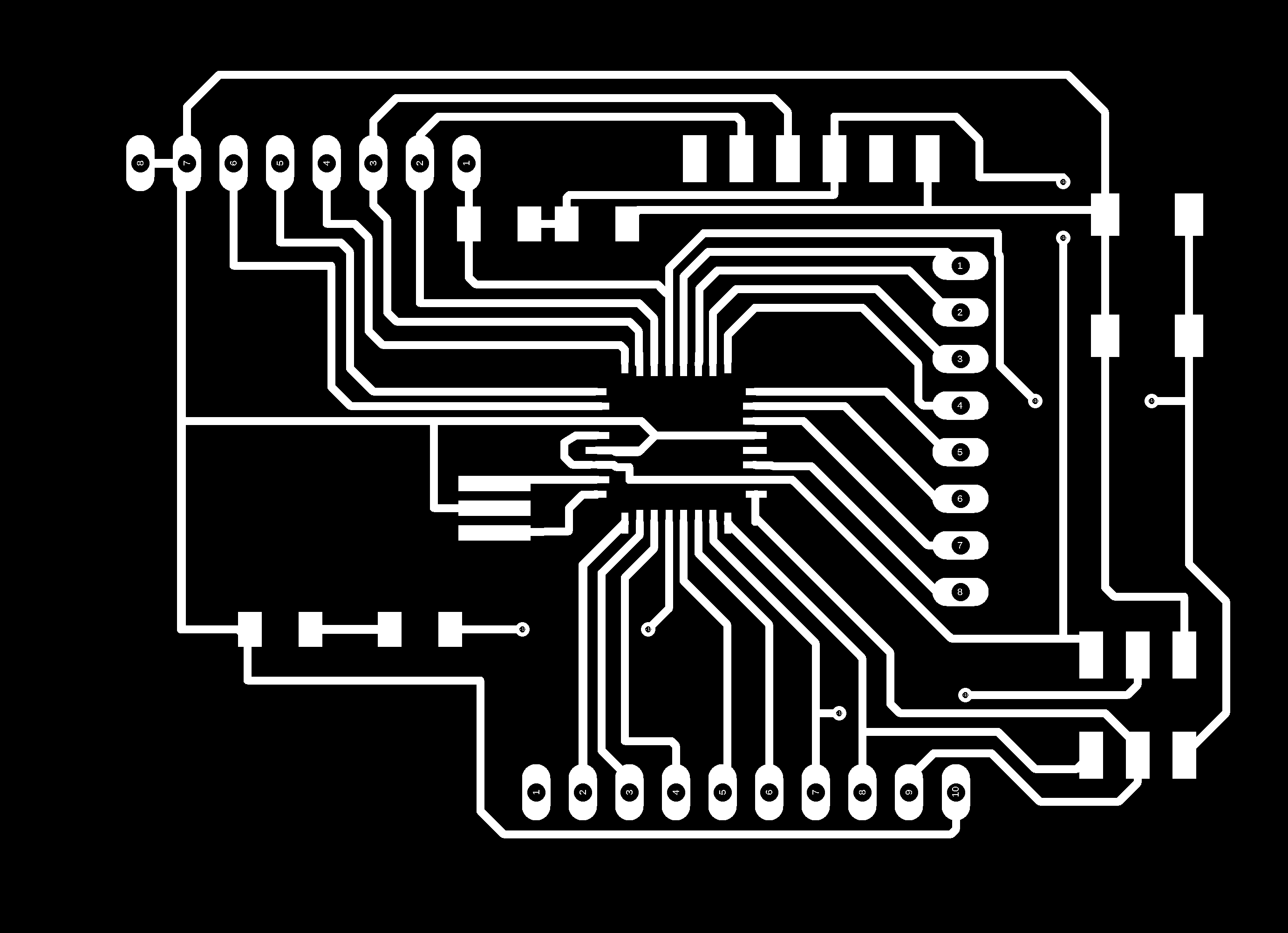
Here is the trace.png image
Here is the cut.png image
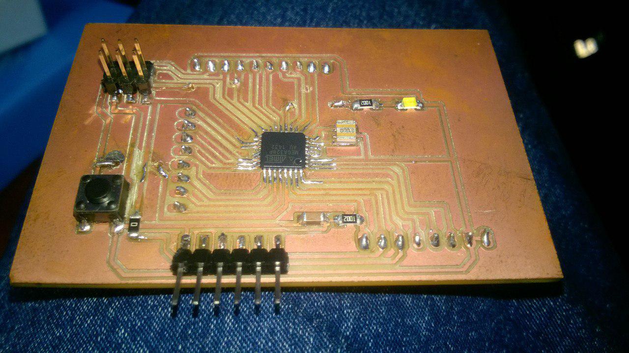
The board is milled out and the I started soldering one by one with the components that I above mentioned
Then I seperatly noted the SDA & SCL for connecting the two circuit's micro controller and also selected the Circuit with ATmeg 328 as master and hello world as slave
 New board
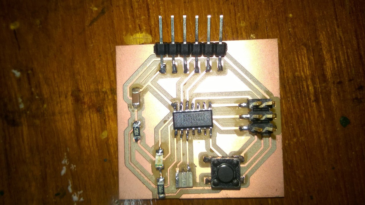 hello world board
3.Programme Using Arduino
For programming I used Arduino now because It is very femilar with me ass using continuous through the week assignment ,for making the codes for both ATmega and ATtiny I download "wire.h and tinywire" file each here the full codes for both ATtiny and ATmega for I2C programming are compressed it into these files in below is the code is that I used for programming my "Maste and slave "
here you can download my programme of "MASTER"
here you can download my programme of "SLAVE"
Here I wrote the programme for makking LED bliking using the communication between the master and slave for each circuit I used different MCU so here I also wanted to downloaded the wire.h file of both mega and tiny ,we can directly install the wire.h file through skectch < addfile but for tiny communication we want to download tinywire.h file
TinyWireM.h for master
TinyWireS.h for slave
Communication programme
I know I am from a different background I trying to use this opertunity for learning the programming ,according to this it was the communication between two microcontrollers I got some help from my instructers the I go forward with a base programme as parts of developing my base
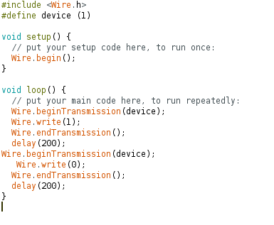
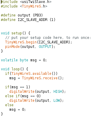
Here Master programme is senting the nuemerical digit "1" the slave programme recieves that and make the LED a on when the master senting the nuemerical digit "0" the LED becomes of ,If the master didn't sent the digit "1" the slave didn't make the LED on this is the communication between the master and slave
MASTER                                                       SLAVE
      #include                                        #include
  #define device (1)                                       #include

void setup() {                                                 #define output (PB3)
  // put your setup code here, to run once:                     #define I2C_SLAVE_ADDR (1)
  Wire.begin();                                              void setup() {
}                                                               // put your setup code here, to run once:
                                                       TinyWireS.begin(I2C_SLAVE_ADDR);
void loop() {                                         pinMode(output, OUTPUT);
  // put your main code here, to run repeatedly:      }
}                                                    volatile byte msg = 0;
                                                     void loop() {
  Wire.beginTransmission(device);                   if(TinyWireS.available())
  Wire.write(1);                                        msg = TinyWireS.receive();

  Wire.endTransmission();                                 if(msg == 1)
  delay(200);                                             digitalWrite(output, HIGH);
Wire.beginTransmission(device);                           else if(msg == 0)
   Wire.write(0);                                        digitalWrite(output, LOW);
  Wire.endTransmission();                                  else
  delay(200);                                                msg = 0;
}                                                               }
4.Working of my Board
After uploade the programme through ISP I connected the master board to ISP for getting the voltage and the I gave the vcc and GND to the slave through the FTDI PINS of master .Then I connected the SDA and SCL of bothh micro controllers externally through a wire and below is the video shows the communication of the board
.sch file of board
.brd file of board
PROBLEM FACED
At first I didnt got idea of why my board gives errors whel uploading programmes
I worked with atmega in this week so when uploading the "wire.h" programme It wont uploaded I felt I am not doing the right way then
I seeks the help of my Instructor 'LANCY FELIX' who gave me the full Idea about the mega and mini controller's communication.
Then I loaded the wire.h file and Tiny wire.h for the each microcontrollers the uploded the programing using arduino
the I got wright