Week 16
Machine Design
The assignment for this week was basically a group project and it required a group to plan and make a machine. being the only one taking the class in my class Node, I desided to work with my local lab instructuor to build a CNC machine based on Nadias moduler machine mechanism which I designed built and tested manually during the mechanical design week.
Design and Fabrication Process
Taking into account the Mechanical design week assignment, I started the design process by brainstorming with my Lab instructor to come up with a way to combine the mechanism to form an X,Y,Z machine which will be intended for milling borads. we came up with about three different designs but ended up picking the design shown below.
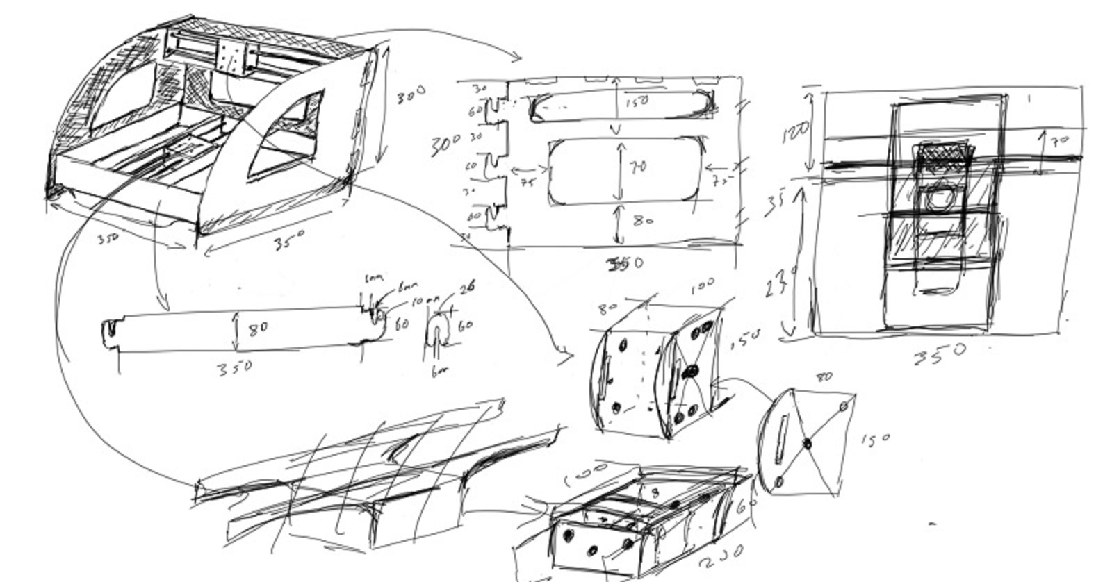
Designing the Mechanical parts of the Machine
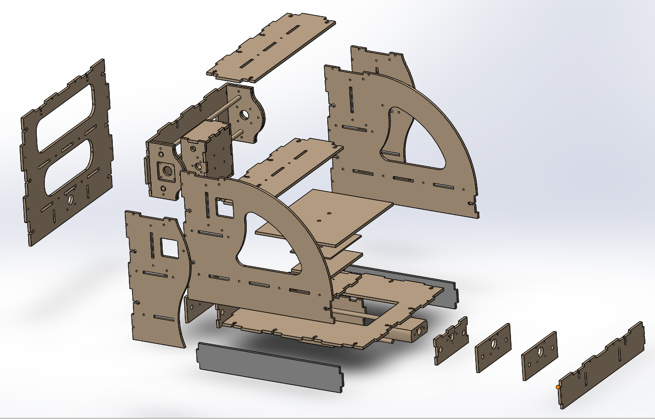
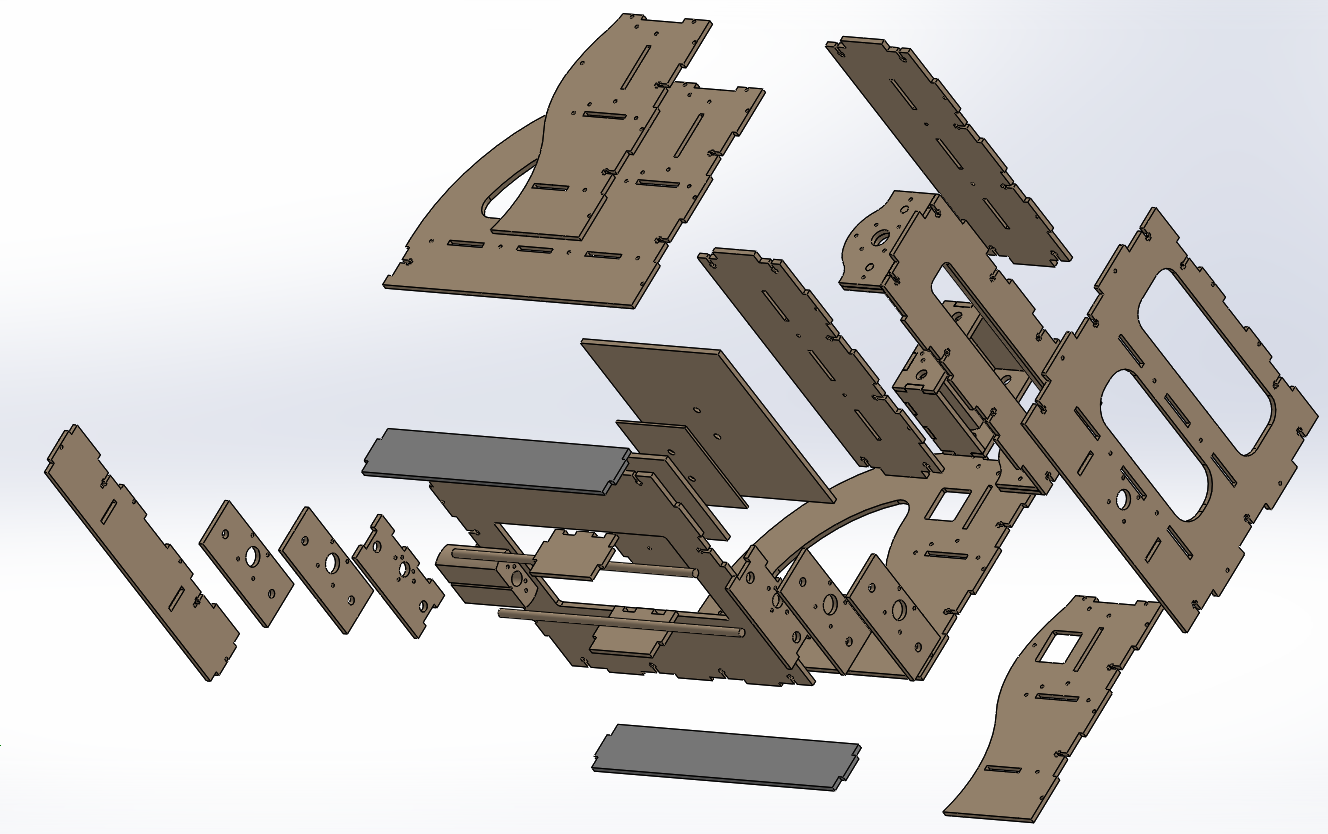
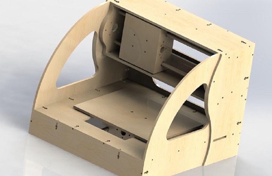
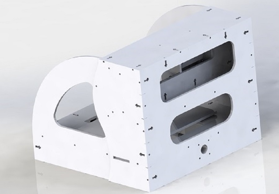
After we desided on what macine design to build, we started adding detailed measurements of the mechanical components that makes up the machine. the list below shows major mecanincal components of the machine. We then devided the machine parts between the two of as and designed all the parts using SolidWorks. We then brought the parts together and virtually assembled the parts in SolidWorks to make sure all the part works well together. Images below shows the rendered exploded and assembly view of the machine.
Exploded and Assemply views of Machine
Mechanical Part List
* Fasteners
* Nema 17 4 start 2mm pitch 8mm d
* Nylon Bearing, Flanged, for 3/8" Shaft
* 6mm thick MDF board
* 8mm diameter aluminium pipes
* 3D printed Bushings
Cuting/Making the Parts
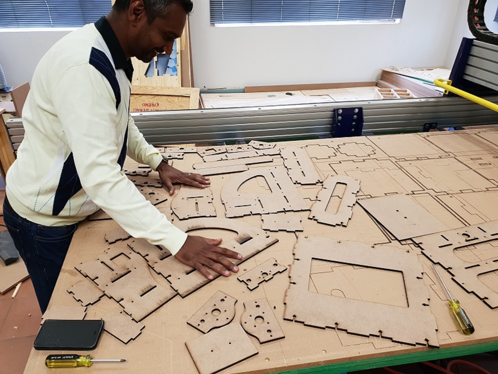
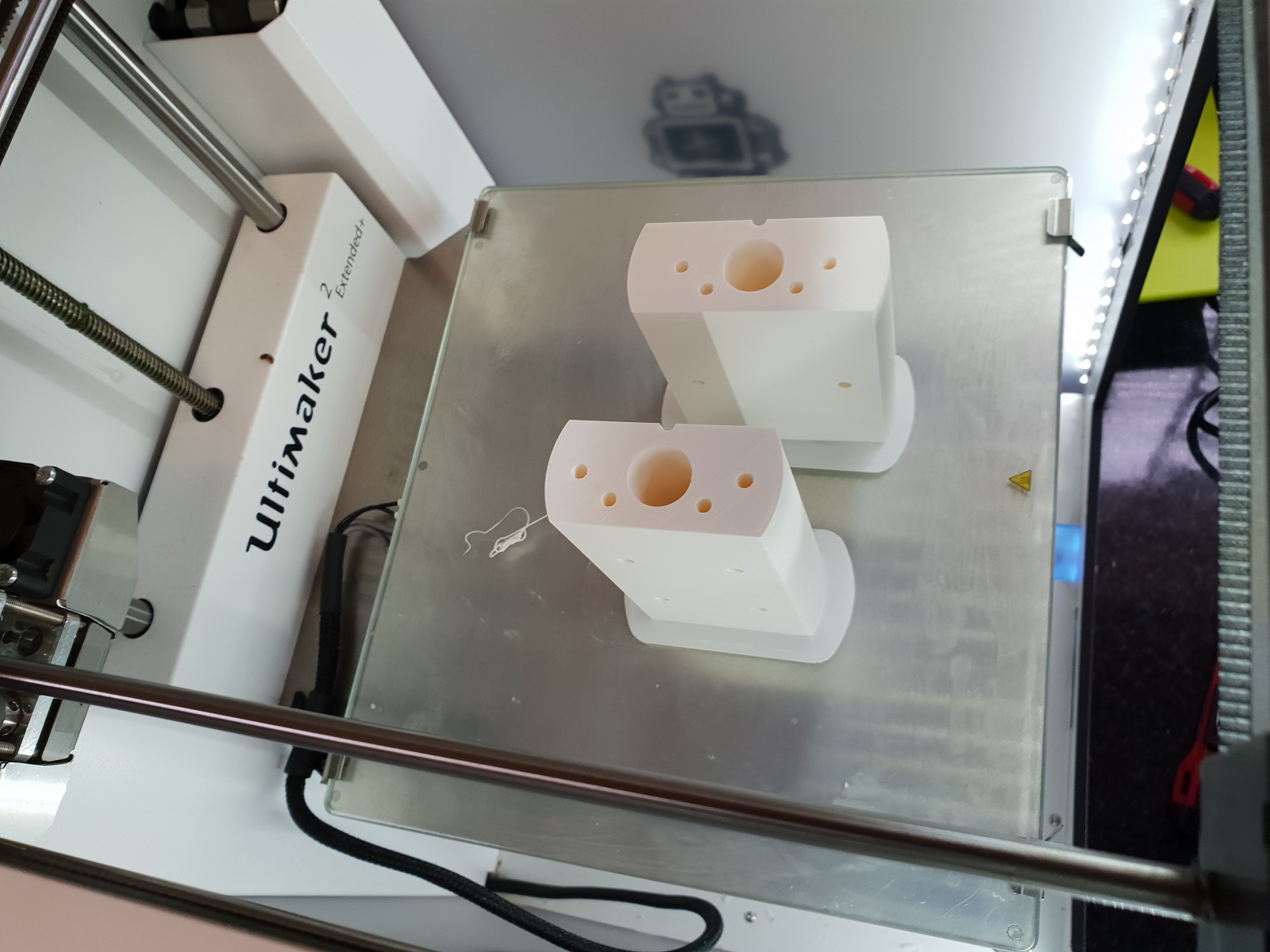
After assembling all the parts and correcting all the errors, we were ready to cut/make the parts. So I converted all the parts to DXF and STL for processing with the Laser cutter and 3D printer respectively. See photos below. We then assembled the part and were ready for the electronic and programming parts.
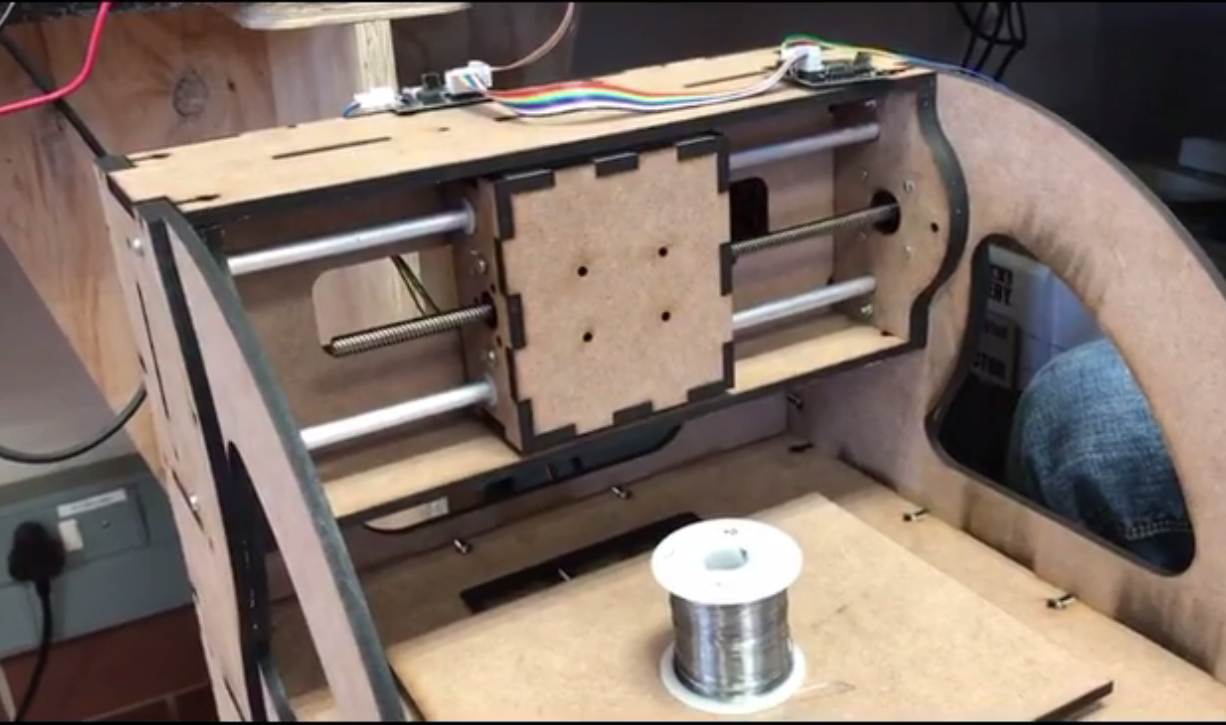
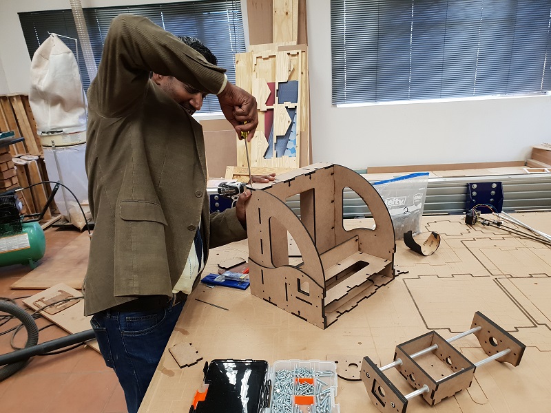
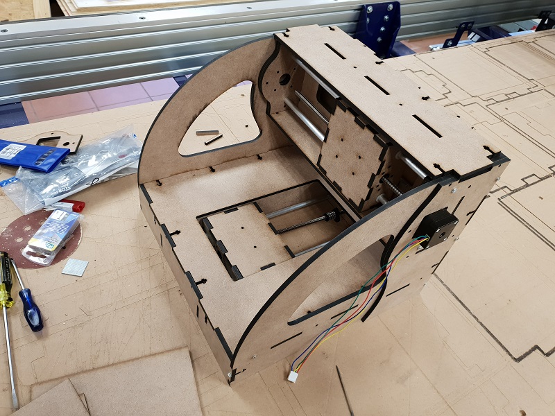
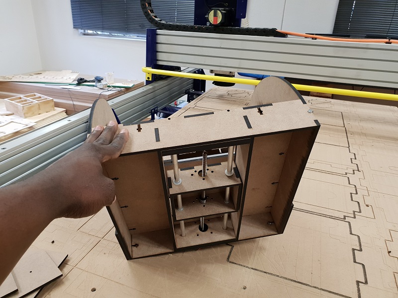
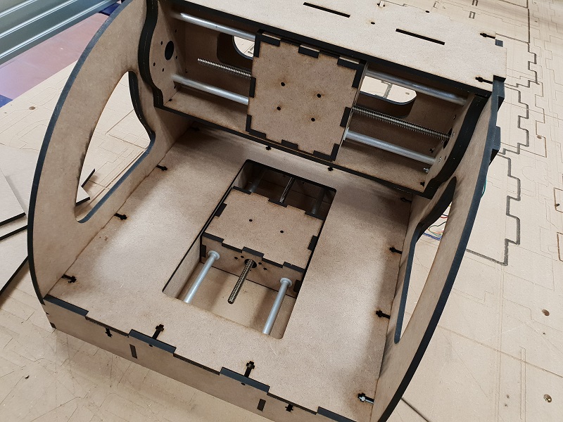
Assembling the parts
After all the laser cut parts and the 3D printed parts were ready, I put them together with the help of my lab instructor. See photos below for assembled machine.
Puting together the electronics and programming
After assembling the machine, it was time to try and put life into it. We downloaded all the necessary board files and programs from the MTM site here. You can also download the mill trace file for the ftdi-cable-connection boards below.
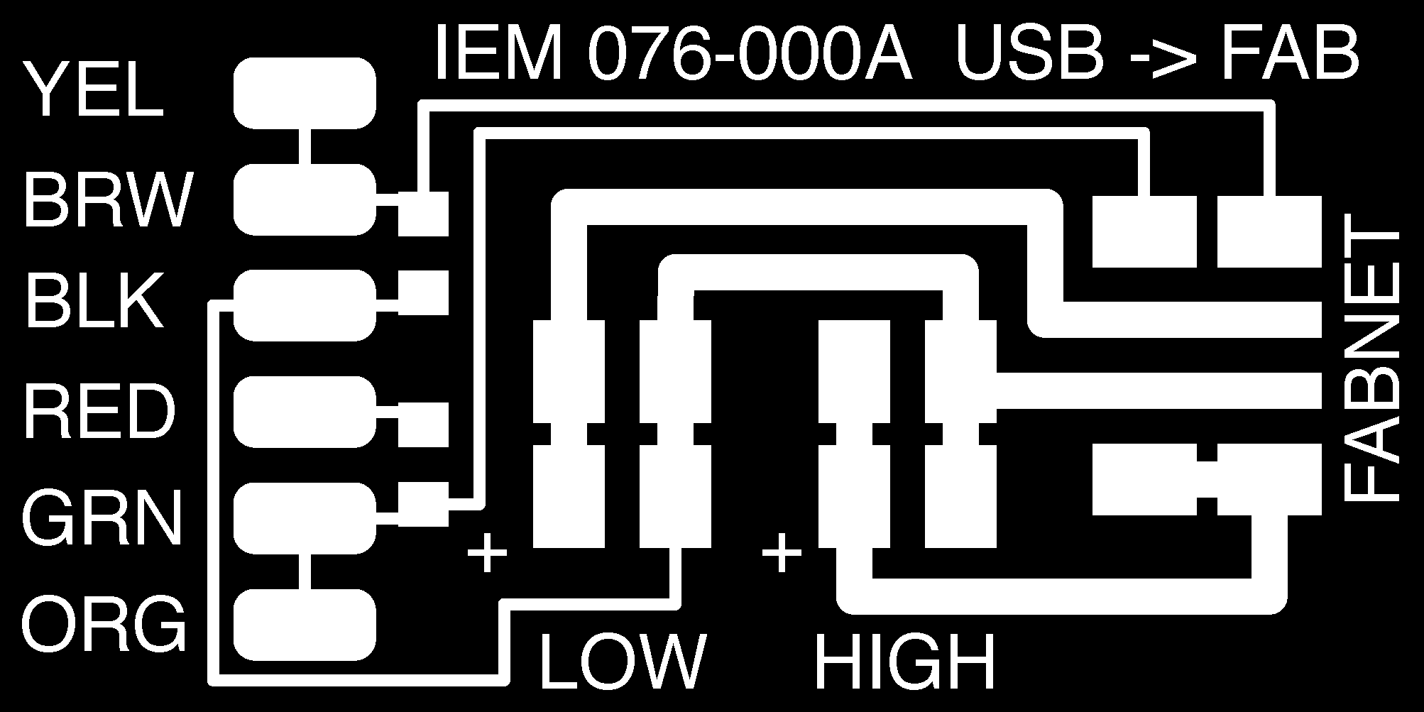
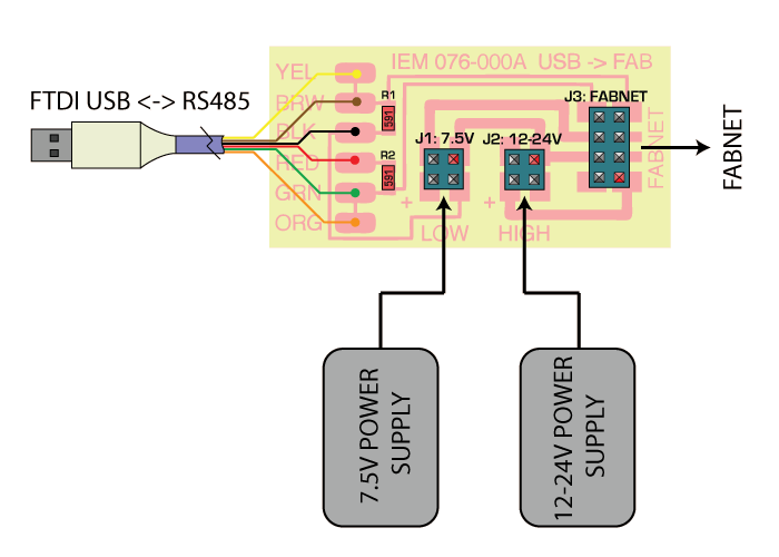
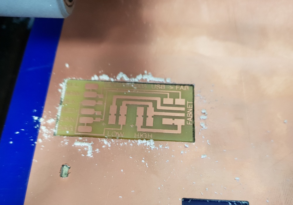
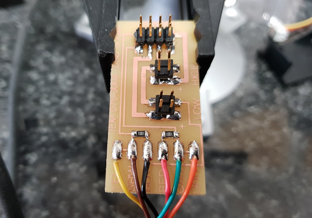
I then milled and soldered the FTDI connection board and soldered it with the connectors and the ftdi cable. See photos below.
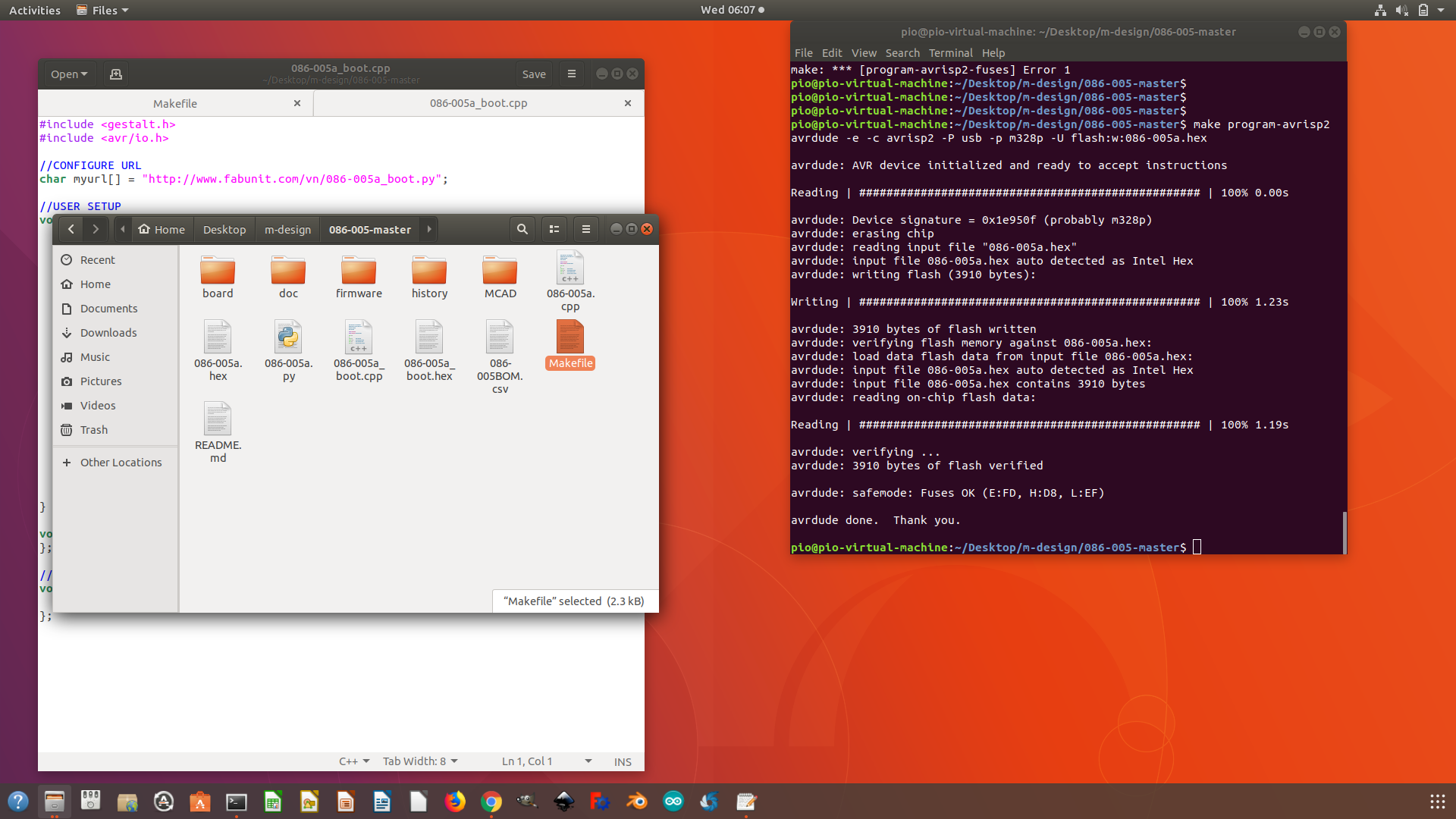
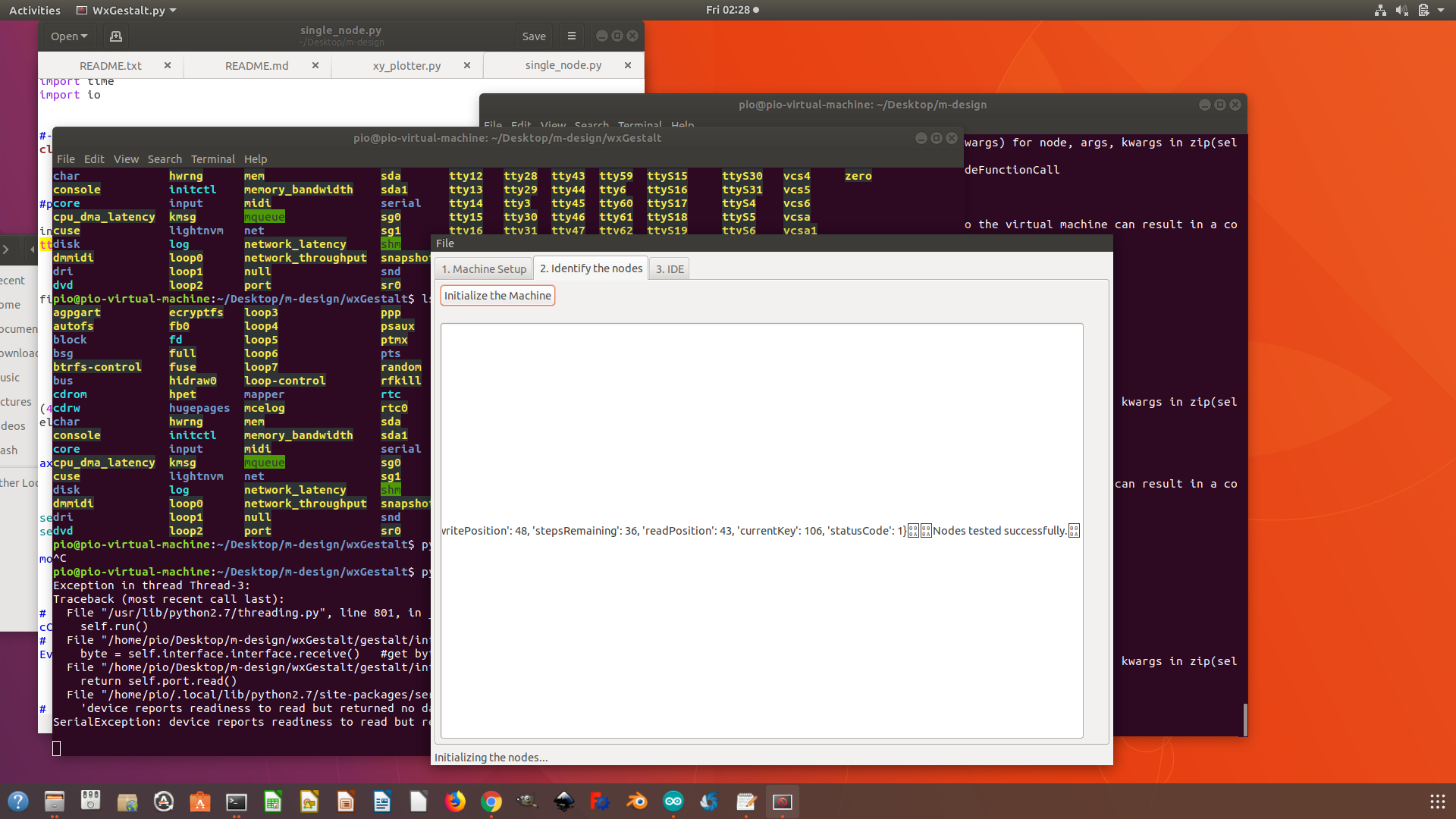
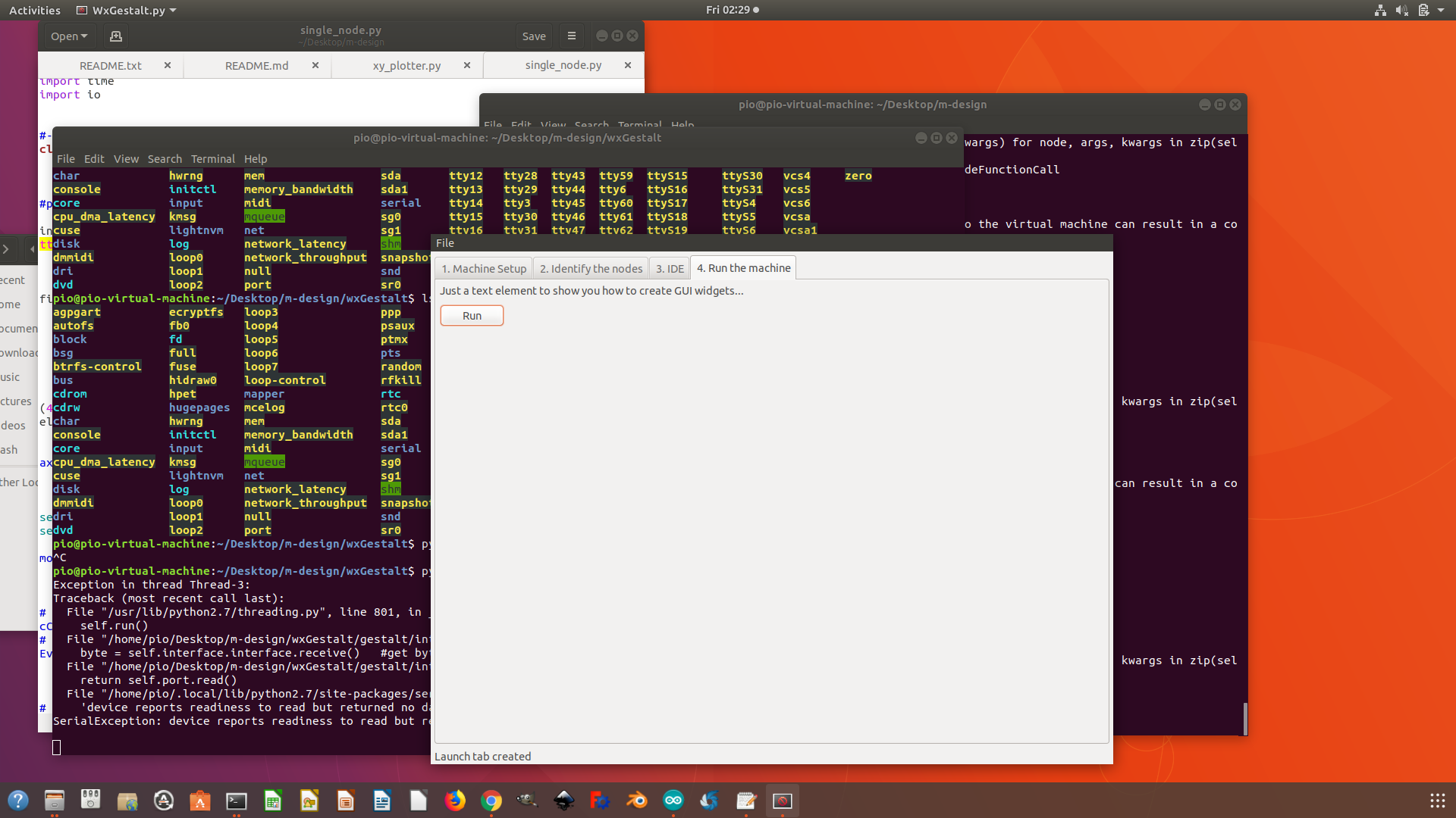
Programming the Gestalt board
I then downloaded the make file, the C files and the python codes and programes needed to program and run the gestalt nodes. i went through the process of modifyig the make file and programming the boards using the AVRISP and the fab FTDI connector shown above and then run some test moton using the python program (wxGestalt) to see if the programs loaded correctly to the nodes. Photos below shows the result for the programming of the boards.