Week 14
Networking and Communication
The assignment for this week is to design and build a wired or wireless that intergartes at least teo processors. I decided to do the serial bus communication using two nodes and a bus. One of my main reason for choosing the serial bus communication for this assignment is to try and understand how it work so that I can apply that know in my machine design project as I plan to in future build a cnc mill using the serial communication (Nodes).
Design and Fabrication Process
Once I have desided that I am buiding the serial bus communication, I started the process by downloading all the necessary files from the class site. Download files below.
Click links below to downloads Design file


After getting all the design files (the bridge and the node files), I then processed and milled the files using the SRM-20 milling maching and the Fabmodules. I then soldered the boards with reference to the component below. Images below shows components used and the finial soldered board.
Components board
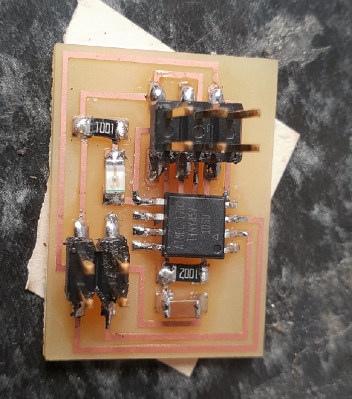
Soldered Node Board
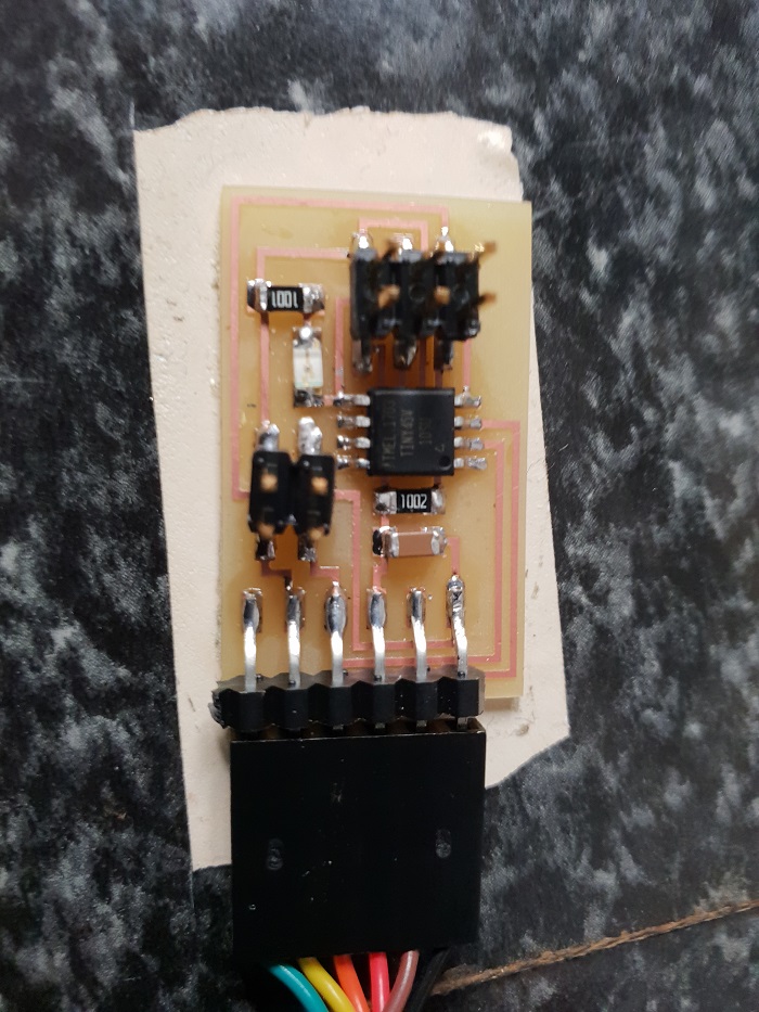
Soldered Bridge Board
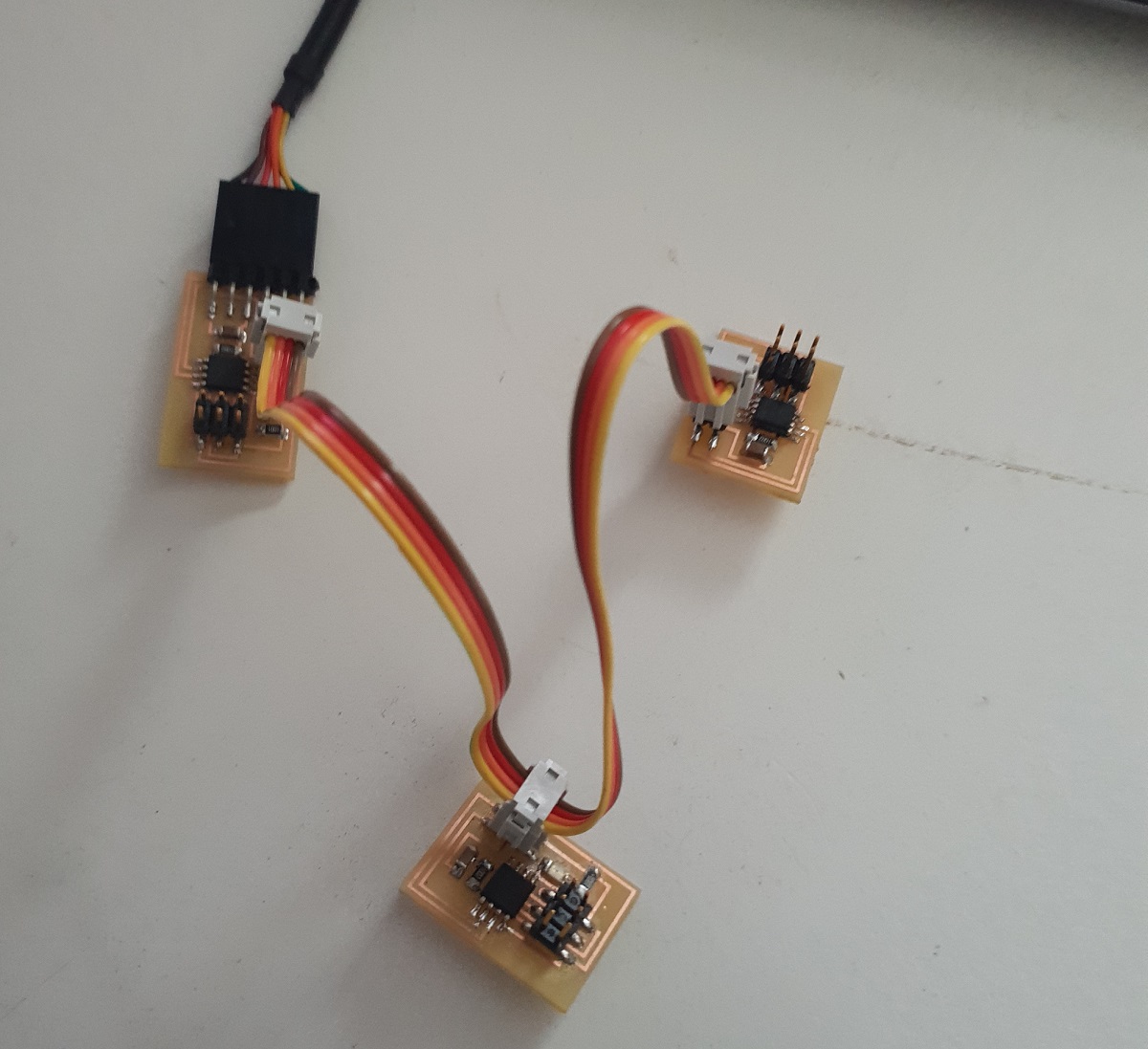
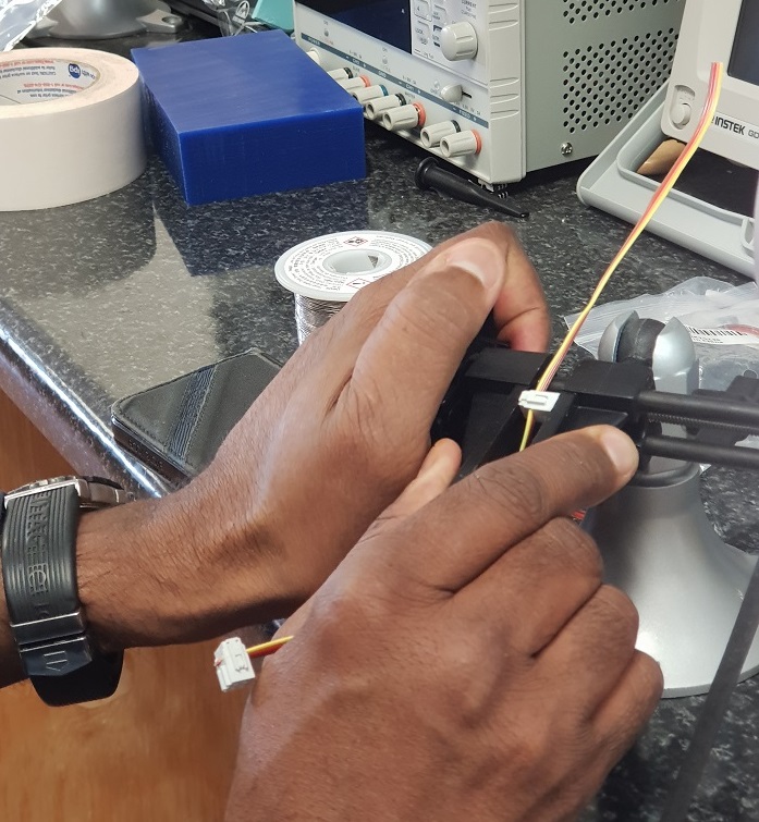
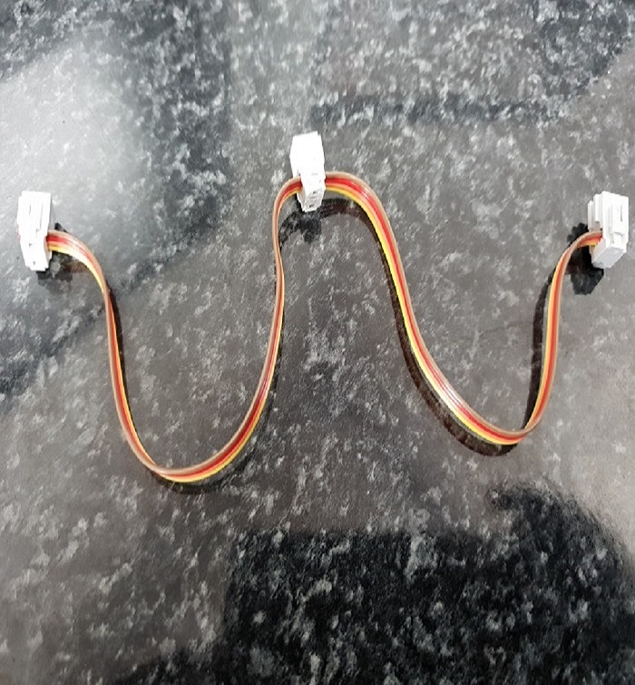
Making the serial cable and Programming the Boards
After my boards made th serial connection cable with the help of my local iinstructor, see Images below. The cable has three terminals, one each for the two nodes and the third for the bridge, which also connect to the computer through the FTDI cable.
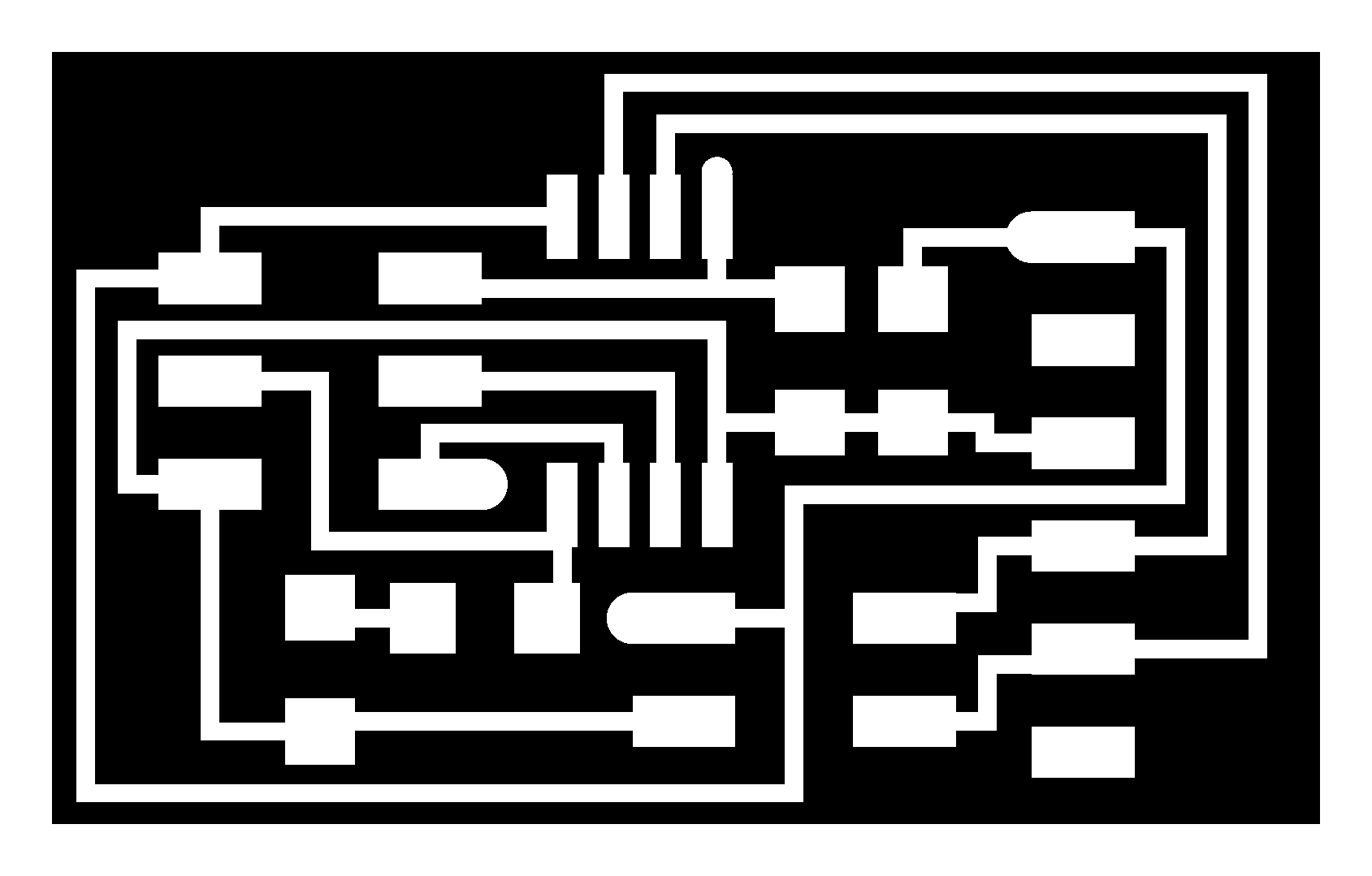
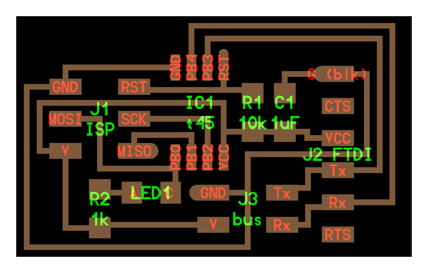
hello.bus.45.bridge.traces.png
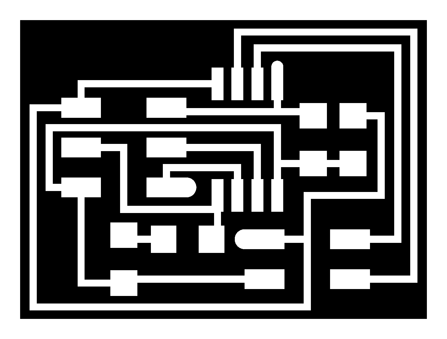
hello.bus.45.bridge.interior.png
Programming the Boards
After my boards and cable were all set and complete, I was ready for the programming part of the project. So I downloaded the sample C program for the nodes, the make file and the terminal files from the class site. Files can be found at the end of this page. I then connected the boards together and then connected it all to the computer with the FTDI cable via the bridge board. With help form my local instructor, I was able to identfy the node ID and then edit them to correspond to each node. Using the Ubunto terminal, I was able to edit the make file to correspond with the c programs and the generate the hex files which I then loaded to the boards again using the make program command on the terminal via the FabISP. See photos below.
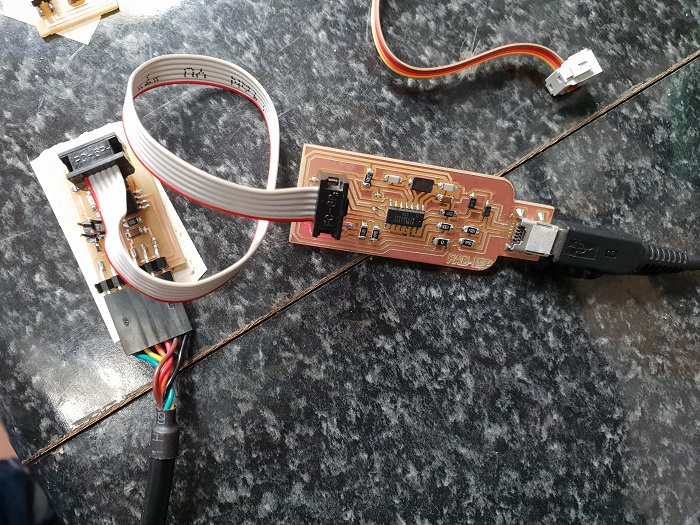
Programming nodes with FabISP
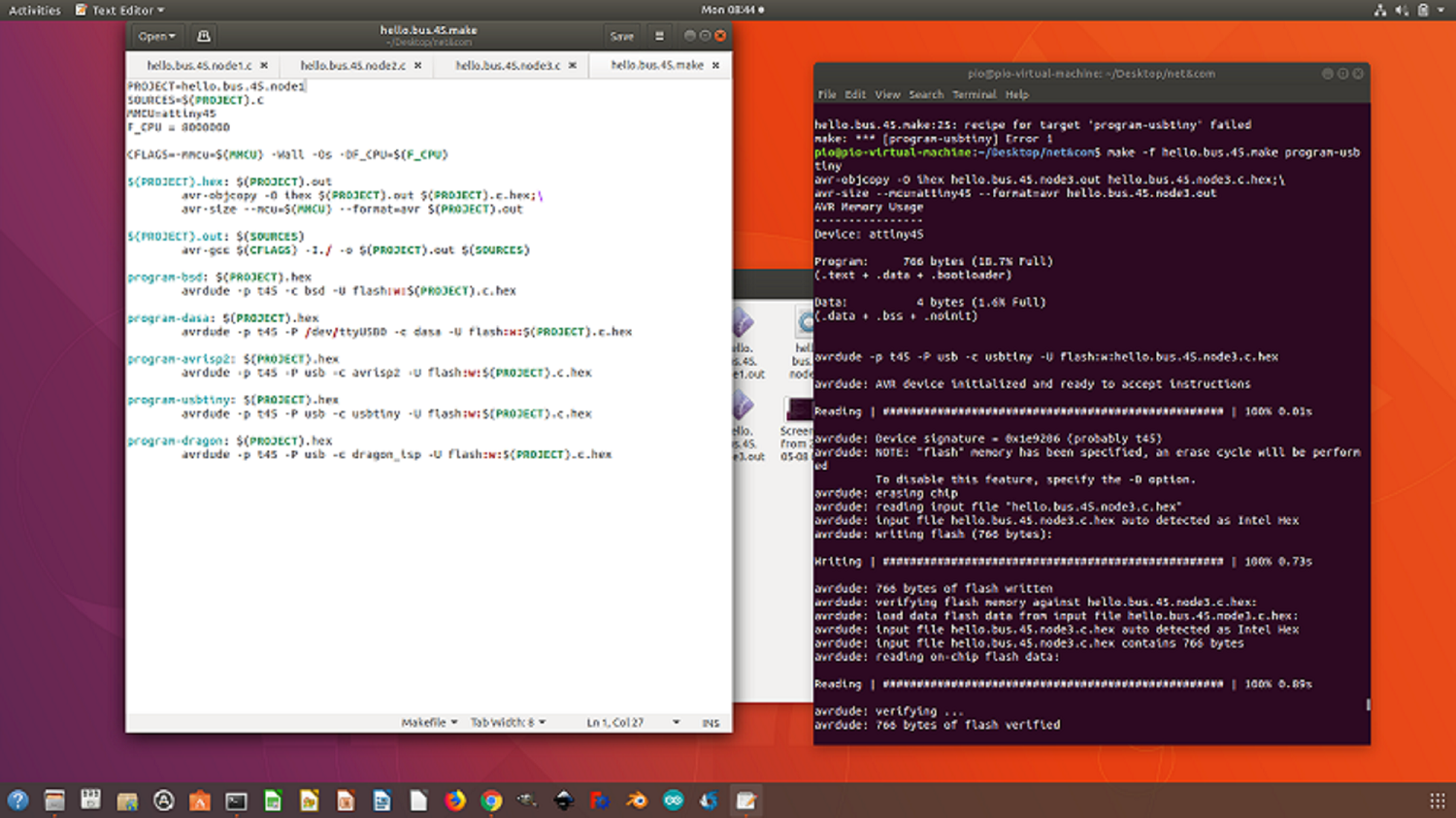
Programming node1
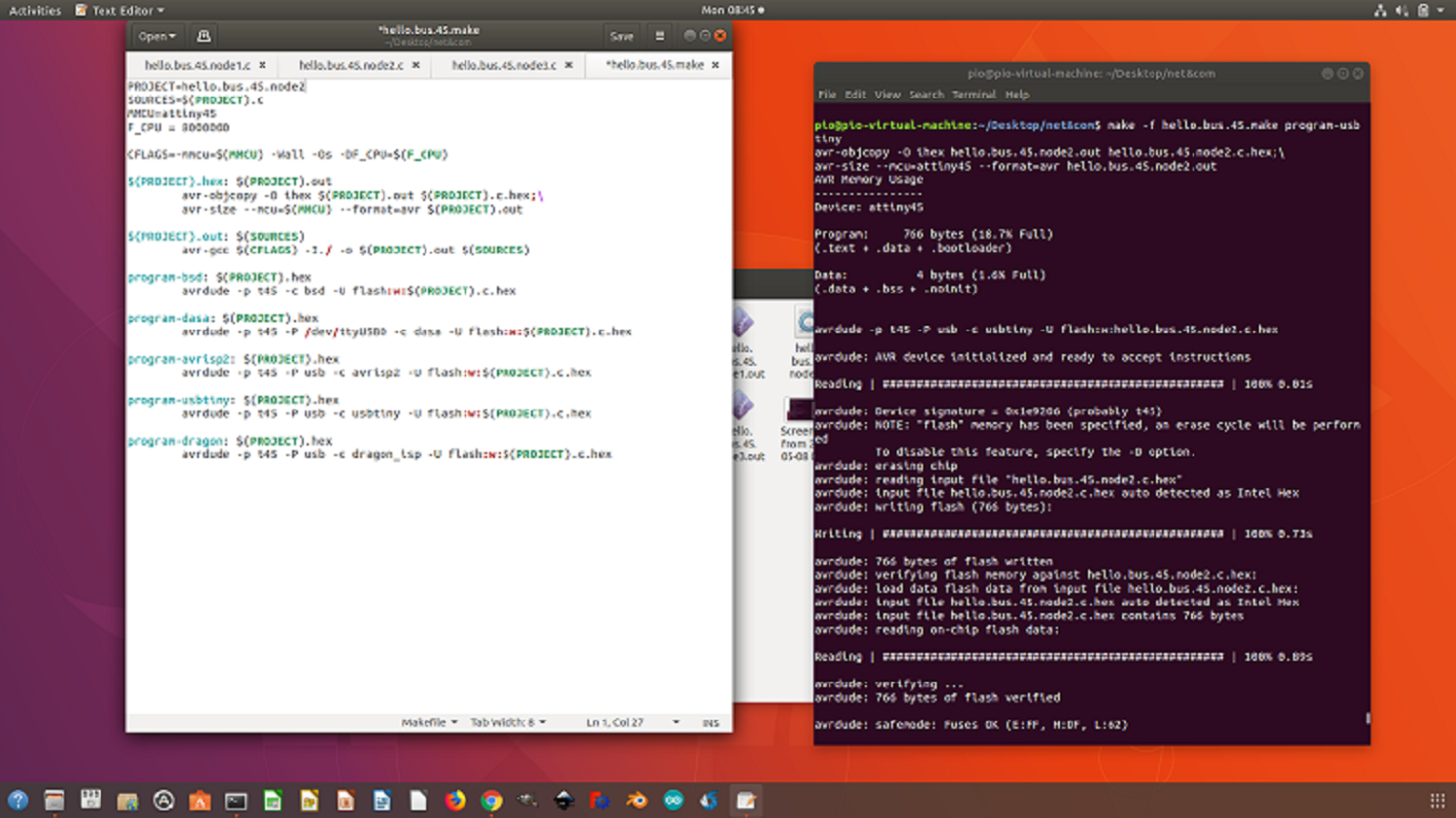
Programming node2

Programming node3
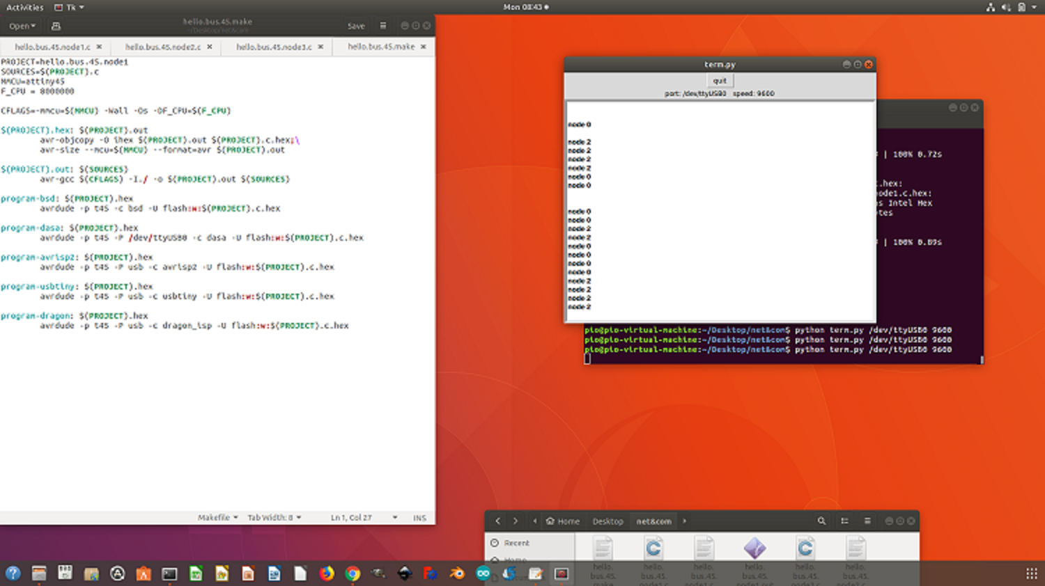
Testing the nodes after programming
After programming the boards,I run a test using the python terminal program from the class site. I had to do quite a number of trials before finallygetting it right. I tried different baud rate before finally finding that the correct baud rate was 9600. See photos and demo Video below.