Week 12
Output Devices
The goal of this weeks assignment is to help us understand and make devices that can accept instructions as input and deliver them as output. We are for this week to add an output device to a micrcontroller board design and program it to doo something.
My Assignment target
For this assignment, I decided to experinment with the servo motor as my output device so as to understand how it functions. I chose to do the servo motor because I plan to use it in my Final Project to control my fish food feeder delivery mechanism. Below are the steps I went through to make output device.
Downloaded files
I downloaded all the necessary from the class website under output devices. The list of files I downloaded include the attached files below.
hello.servo.44.traces

hello.servo.44.interior
Going through the circuit board milling process with the fabmodule and the SRM-20, I milled out my board and then soldered it. See photo o milled and soldered board below.
Milled Servo control board from class website
Problem Encountered
After milling the board, I connected it to a 9volt power in attempt to connect it to my computer and program it only to realize that the voltage regulator on the board had turned bright red and there was smoke coming out of the regulator. See attached burnt regulator below.
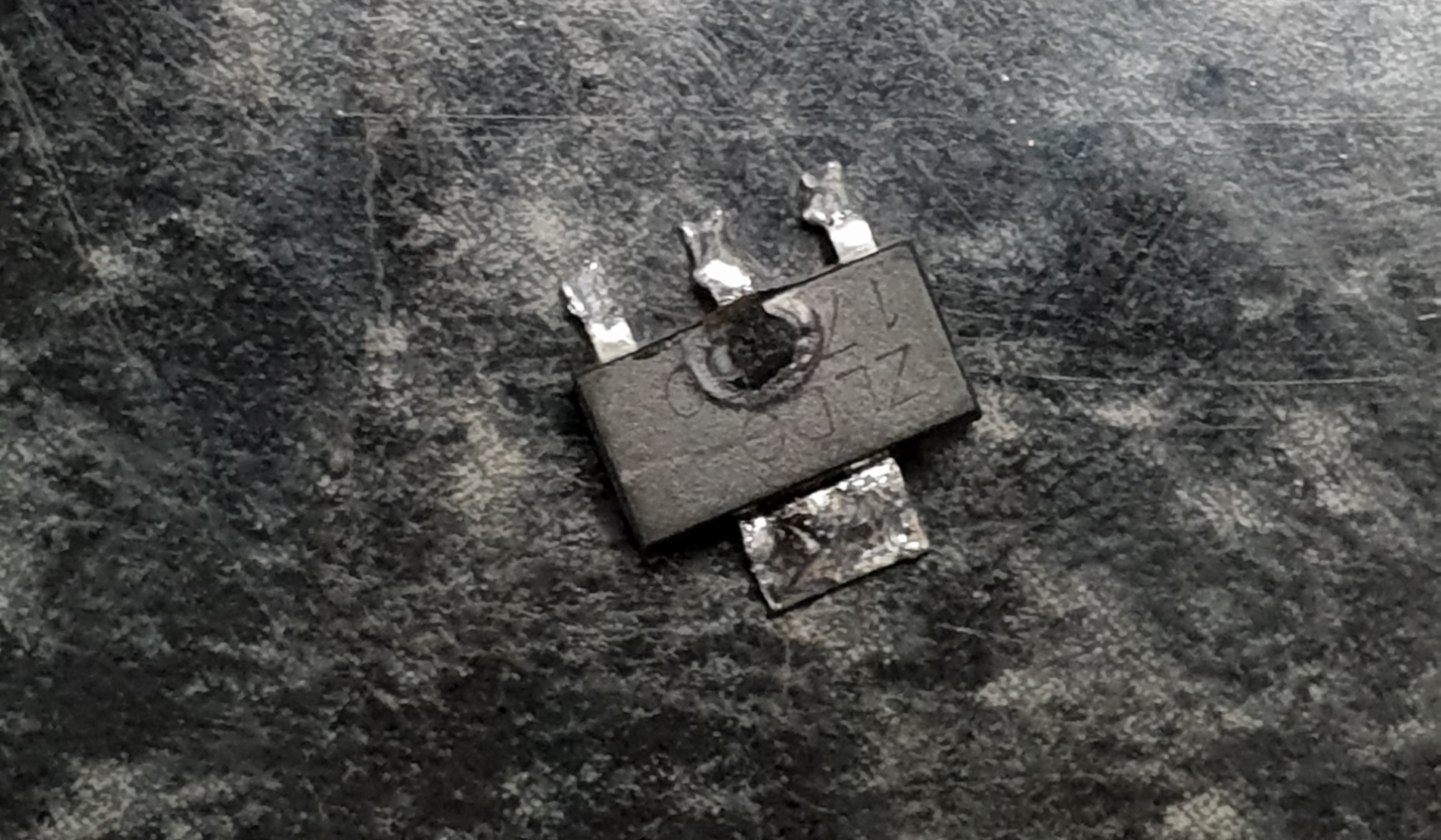
Burnt regulator from smoke test.
It was only after the regulator got burnt that I went back to check the data sheet of the regulator we have in the lab as compered to the one on the board I downloaded. I realized that the regulator we had in the lab was different from the one on the board because they had different inputs and output pins. This lead me to believe that the regulator got burnt because I wwas passing current through the wrong pin.
Solution to Problem
To correct this error, I decided to redesign the board based on the current one on the class site and the regulator we have in the lab. Using the EagleCAD program, I redesigned it and generated the PNG files fro both the trace and the cutout. See image of new board below and find attached trace file, cutout file and CAD file below.
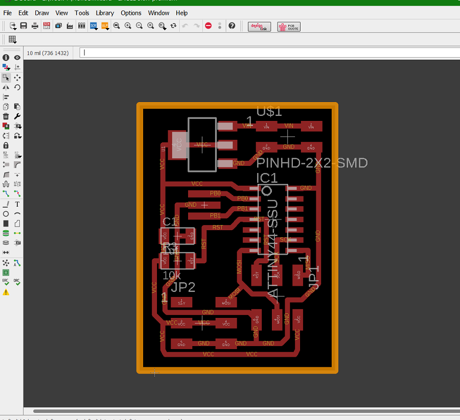
New board with correct regulator
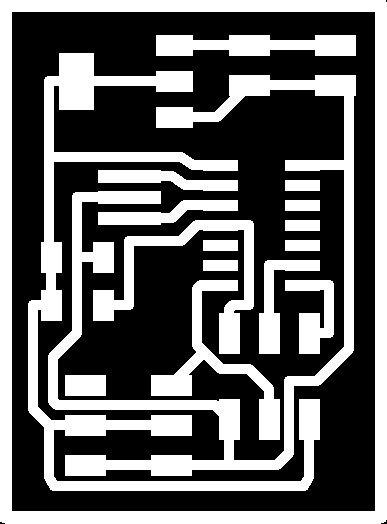
New servo trace

New servo cutout
Download files below
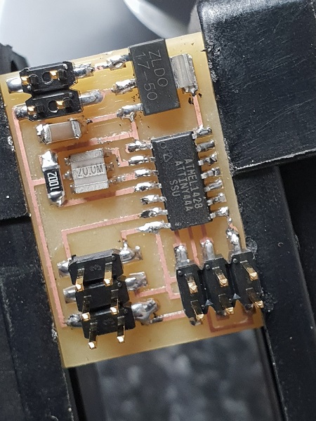
I then milled the new board with the correct regulator, soldered it and did a smoke test to be sure nothing was wrong before I connect it to my computer for programming. It was a success as I did not see any smoke coming out of the board. find photo of new soldered board below.
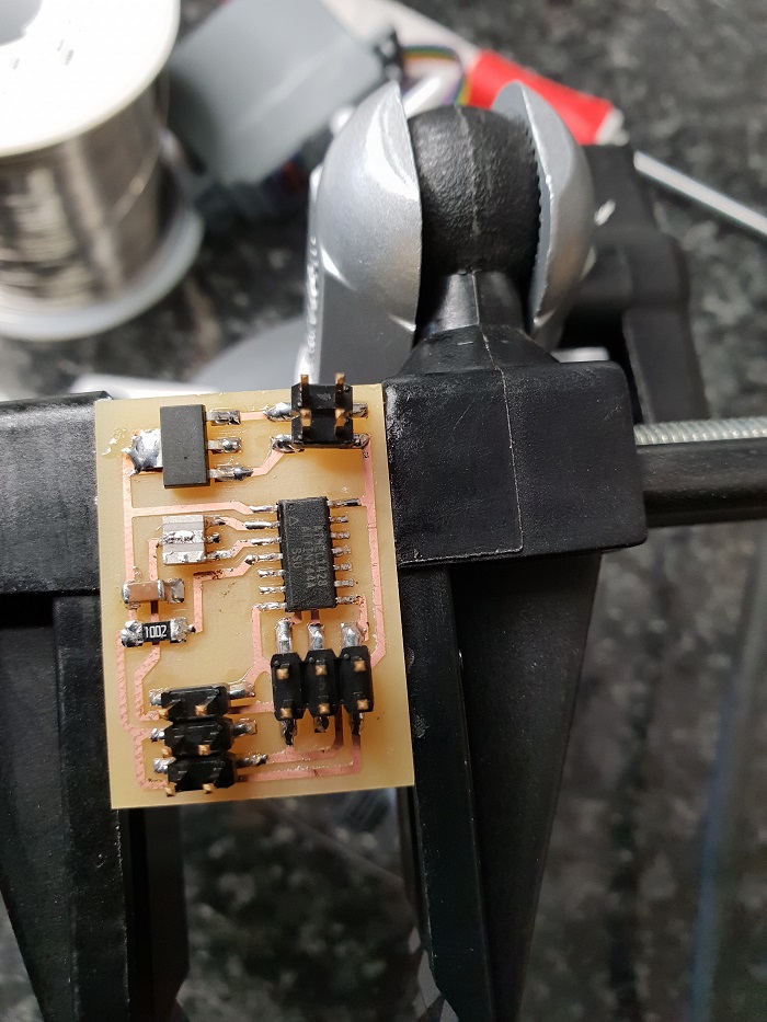
My newly modified sesrvo board
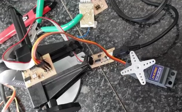
I then connected the board to the power and then to the computer using my fabISP and then programmed it with the Arduino IDE using the c code I downloaded from the class site. find photos of new soldered board below.
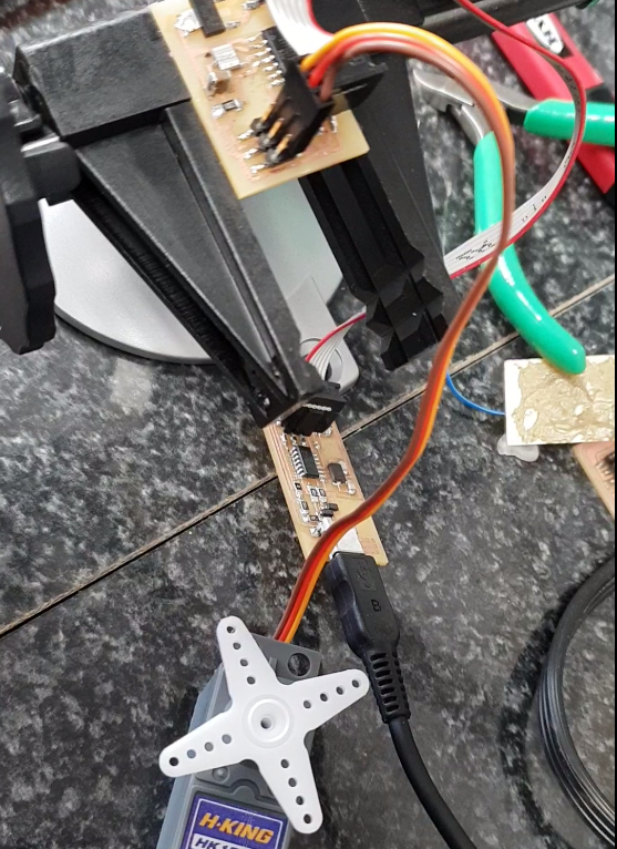
Connected board to my computer
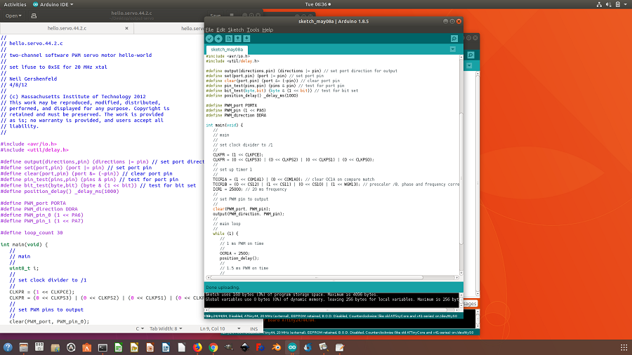
programming my board using the Arduino IDE As per the output devices week, I used Neils code, but if you want to learn about output devices programming you can check my final project page