Week 08
Computer Controlled Cutting
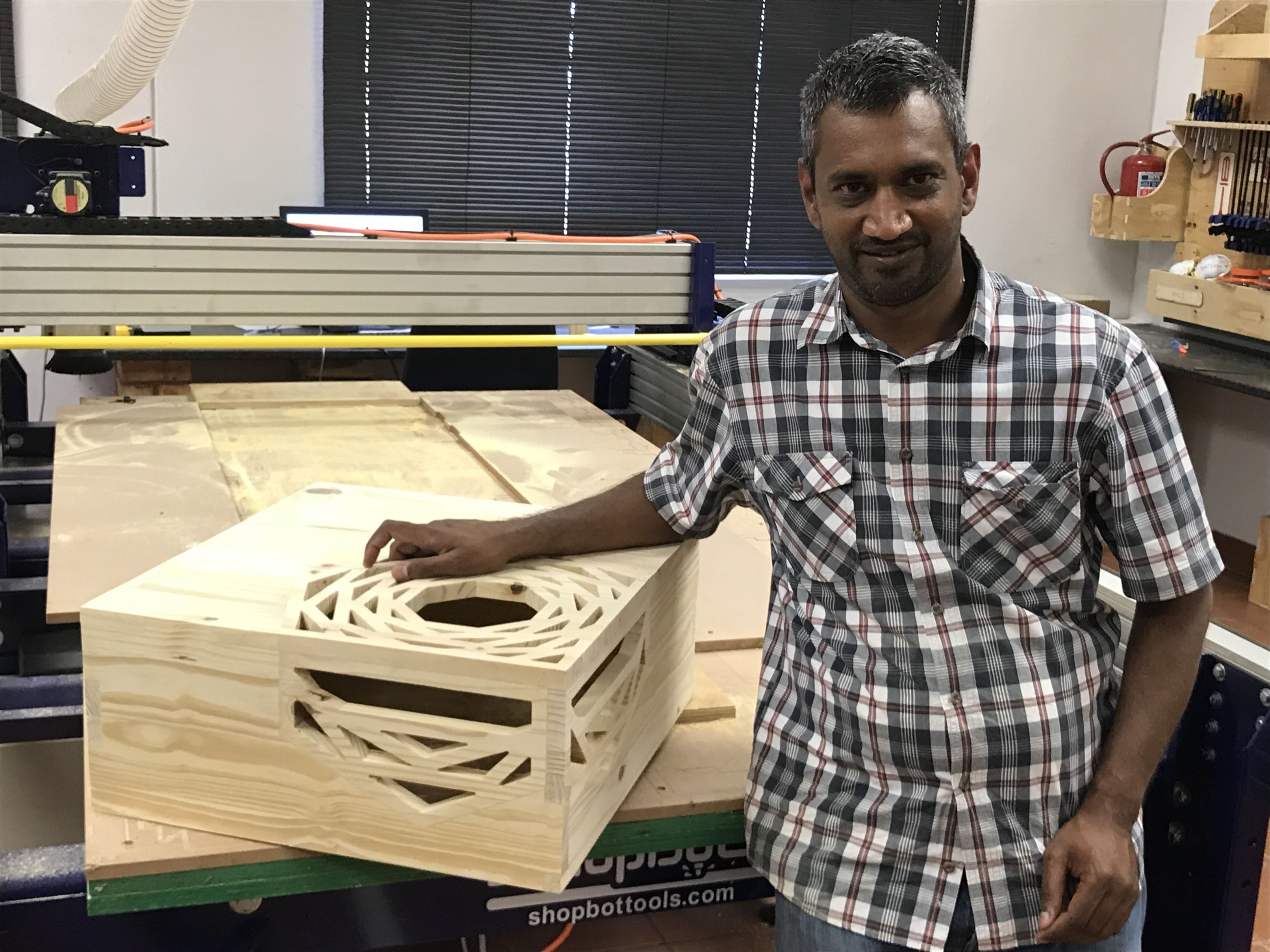
For this weeks assignment, we are to make something big using the shopbot. Insteasd of making a new design for the assignment, I decided to use my coffee table design from the Computer Aided Design week using a 19mm pine wood (image below). Taking the completed design file from week-3, I exported all the part as a DXF file ready for use with the ShopBot software (Vcarve).
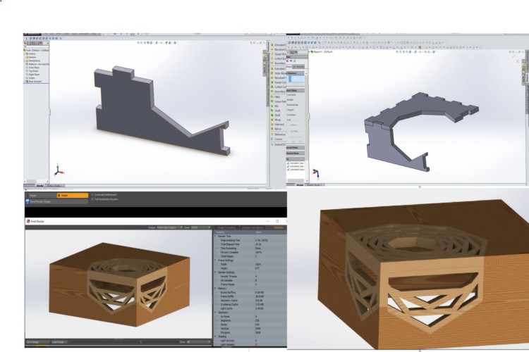
Coffee table design from week-3
Making a Runout Test
Before starting with making my coffee table, I decided to do a runout test to check the alignment, speeds, feeds, and toolpaths for our ShopBot machine. Using Vcarve, I created a datum line for positioning my material which measures (1800mm X 530mm X 19mm) and then drew three squares measuring 50mm X 50mm as shown below.
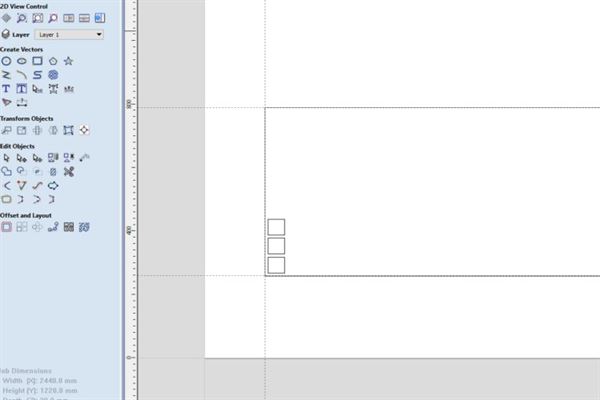
Template and drawing for test runout
Creating a tool paths with varying settings
After creating my datum and 50mm X 50mm square drawings for my runout testing, the squares 50mm X 50mm , I create three different Profile tool paths with three different parameter settings (feed rate, plung rate, cut dept and number of cut). Below are the steps followed in cutting my test files and the outcome of the three cuts.
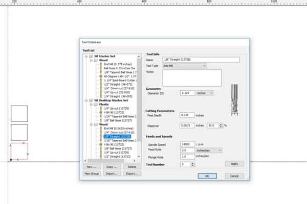
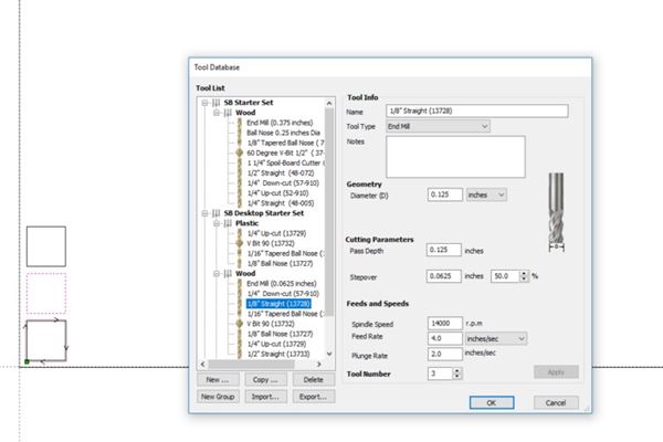
Speed Test 1 : (Spindle speed= 14000 r.p.m , Feed rate= 2 inches /sec, Plunge rate =1 inches/sec)
Speed Test 2 : Spindle speed= 14000 r.p.m , Feed rate= 4 inches /sec, Plunge rate =2 inches/sec
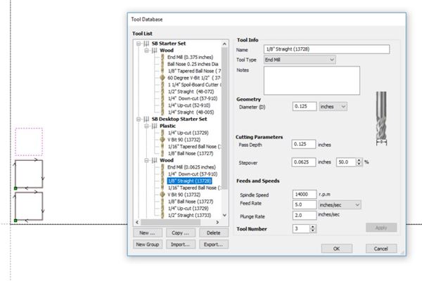
Speed Test 3 : Spindle speed= 14000 r.p.m , Feed rate= 5 inches /sec, Plunge rate =2 inches/sec
Getting the ShopBot ready for Cutting
Getting the ShopBot and the ShopBot Control software ready for cutting was a bit more easear than I anticipated. I had to place my material in the datum line I created and make sure it's very well held in plase. I then changed my bit to the correct size bit and then opened the Shopbot software to set the coordinate for the machine, I made sure I had the X, Y zero coordinates using the xy proximity sensor, I then used the z-zero plate to set my z-zero relative to the material. After getting the machine and the material ready, I then opend the ShopBot control software for cutting my files. I loaded the files one after the other for cutting after getting all the settings correct.`
Changing the Bit
(1) I moved the machine to a suitable position using the control software from the computer to change the milling bit, in this case I chose to use a 3mm bit.
(2) I then removed the dust cover to eneble me change the bit to the correct one, in this case a 3mm bit.
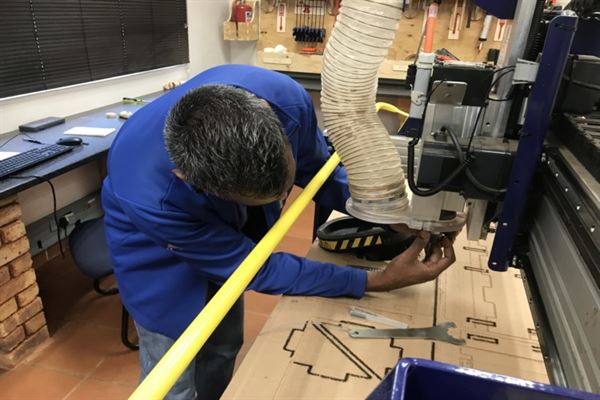
(3) I then removed the bit that was already there and replaced it with the correct bit (3mm bit)
Setting up the Material
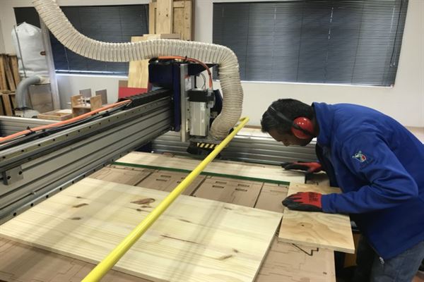
(1) After changing the bit, I created a Jig by first created a datum line to position the jig to hold my material in plase for cutting.
(2) I then incerted the material into the jig and held it flat in position from the corners using screw. I would not have had to use any screw if the board were to have no wap
Materail set and ready for cutting
Sending File for Cutting
(1) Aftre generating my toolpath and getting the material fixed in the jig, I had to open the ShopBot control software as shaown below to send the file for cutting.
ShopBot control Saoftware (ShopBot3)
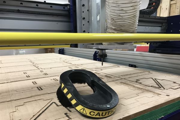
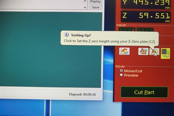
(2) After opening the software, I had to set the x,y,z-zeor positions using the proximity sensors for the x,y coordinates and the zero plate for the z coordinate. The photo below shows the zeroing of the z using the z-zero plate.
Z-zero plate in action.
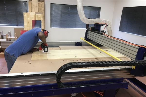
running the test cuts
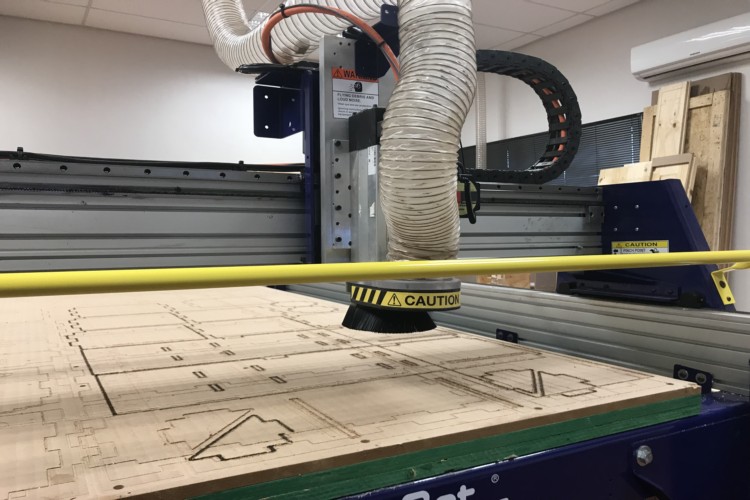
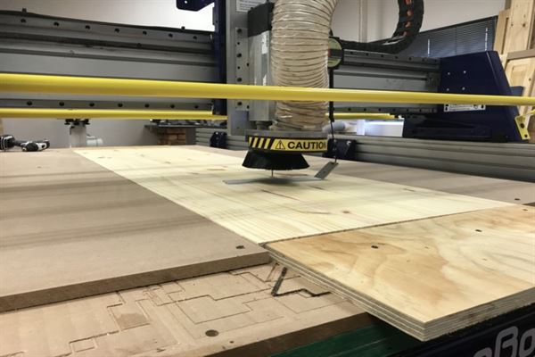
After getting all the axis zeroed, I then sent the toolpath files with the various setting to the ShopBot for cutting. Below is the photo of the ShopBot cutting the files sent from the control software (shopbot3).
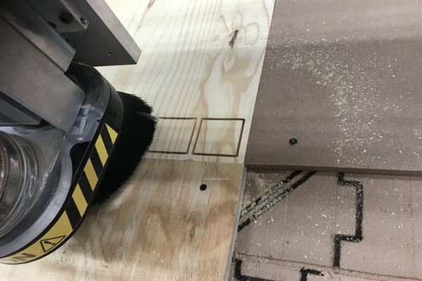
Cutting the squares with different parameter settings
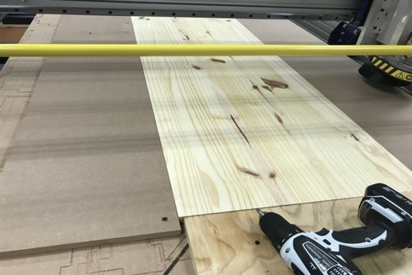
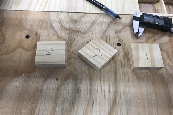
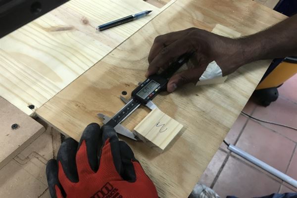
The photos below shows the squares that were cut using the different setting with checking of the measurement for accuracy.
After cutting and measuring, I noticed that the different parameter settings came out with slightly different outcome. The first setting finished cutting in approxiately 47 seconds, the second setting did the same job in about 31 seconds and with the third setting, the job only too about 29 seconds. The output of the three settings was not much of a difference, but from observing the differnce in speed with respect to sound and dept of cut, I realized the third option had a much better setting for the material as it is much safer for the bit I am using and the the output was much leaner compered to the first two settings.
Cut out of test files
checking for accuracy
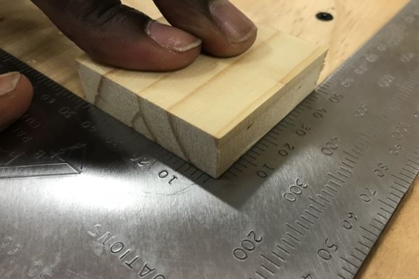
Checking for squareness
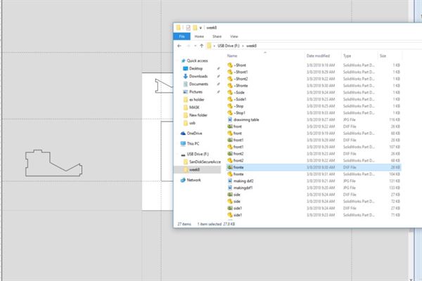
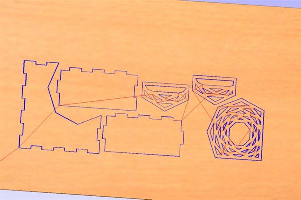
Imported my DXF files from previous week into V carve
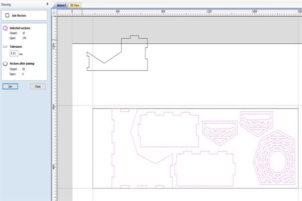
Positioning the parts on work peice and joining all open vectors

Creating the toolpath
Previewing toolpart created
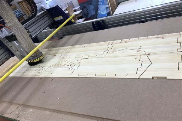
Cutting files
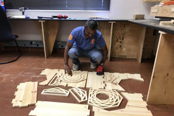
All parts cut, removed and ready for assembly
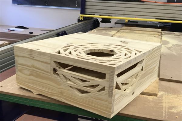
Fully assembled