Week 07
Electronic Design
The individual assignment for this week is to redraw the echo hello-world board from the class site and then add at least a button, LED and posibly some current-limiting resistor, check the design rules and then make it. And for the group project, we are to use the test equipment in our lab to observe the operation of a microcontroller circuit board ( in this case, my hellow-world board ). To start this assignment, I had to make sure I had all the necessary software and hardware available. Below are the software and hardware used for this assignment;
- * EagleCAD
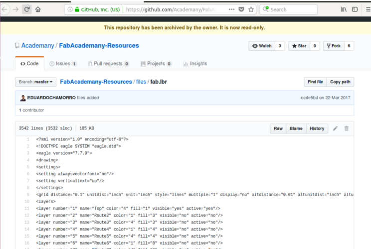
- * Fab electronic Library
- * Milling Machine (SRM-20)
- * FR-1 board
- * Necessary electronic components
- * Soldering station
- * Sample board from the class site
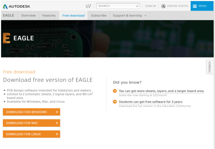
Getting the software
I started by downloading and installed the eagleCAD software and the Fab electronic library for respective sites, Links of the sites can be found below.
Designing my Circuit Board
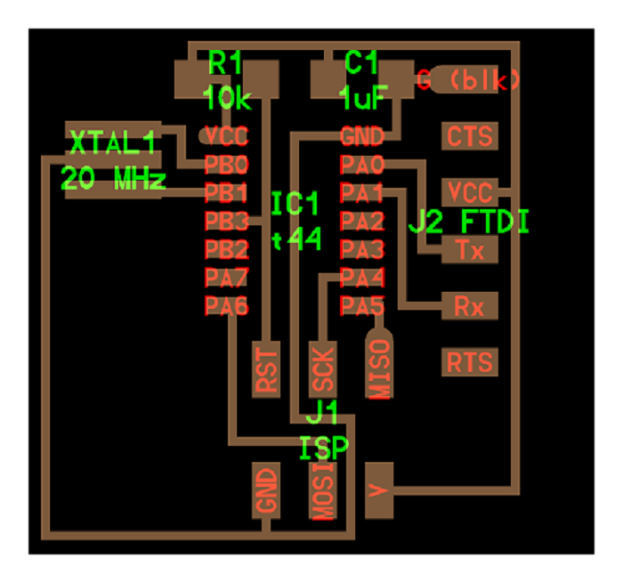
Before starting to design my hello-world board with added button, led and resistors, I had to first get the copy of the hello-world board from the class site and try to understand the pin configuration of the attiny44 microcontroller. So I downloaded the layout file of the hello-world file and the datasheet of the microcontroller to help me with the circuit design. Find links and photos below.
hello-world link
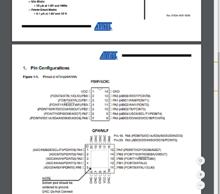
attiny44 datasheet link
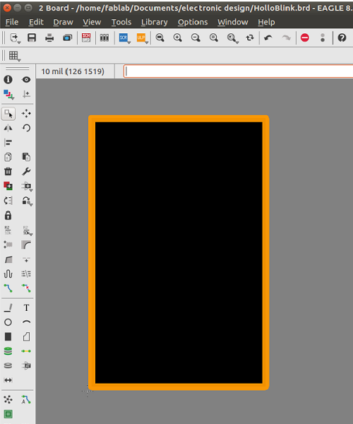
Designing my schematic and Board
I opened the eagleCAD program to start designing my schematics, but not after I was able to I dentify and list all the components needed for building the board. Below are the list of components used;
| * 2 10k resistor | * 1 499ohm resistor |
|---|---|
| * 1 LED | * 1 1uf capacitor |
| * 1 20Mhz christal | * 1 Push Button switch |
| * 1 ftdi connector | * 1 Attiny-44 IC |
| * 1 AVR ISP 6pin connector |
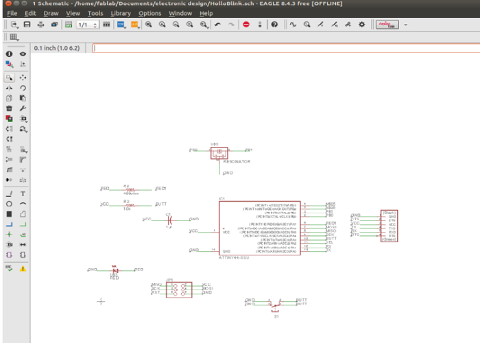
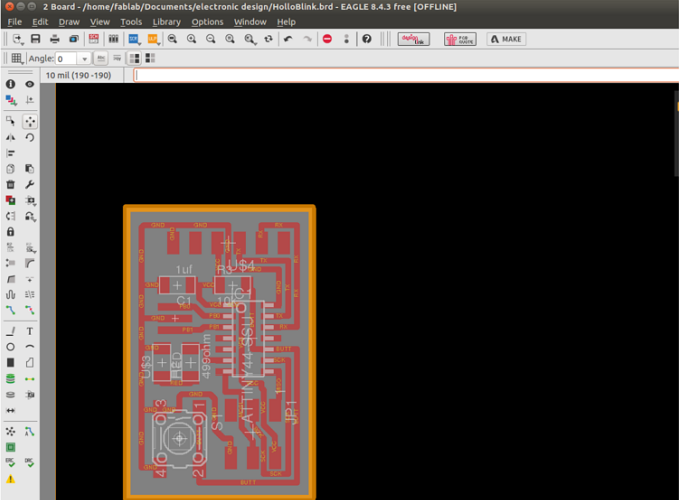
I opened the eagleCAD software and then added my all my components to the schematic and made all the nets connection based on the information I gathered from the hello-world board downloaded from the class site and the Attiny-44 datasheet. Below are the images and link to downloading files of my schematic and board.
Saving File for Milling
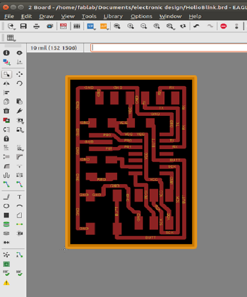
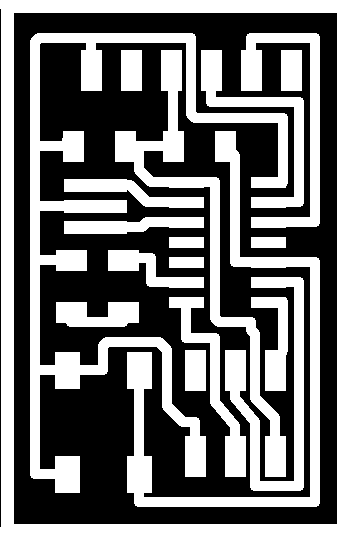
After completing my board design, I had to save it as a png image file to make it possible for import and process by the fabmaodule. I needed two different files, the first to allow for milling of the traces and the second for cutting out of the board after milling. To do this, I had to first hide all visible layers with the exception of the top and dimension layers, which define the mill traces and then export it to a monochrome png. and repeated the same process to export the cutout file. below are the file of the trace and cutout files for download.

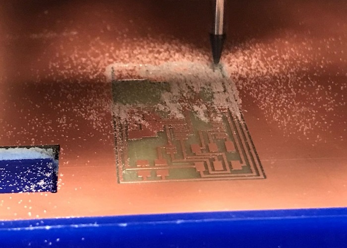
MIlling and cutting the board
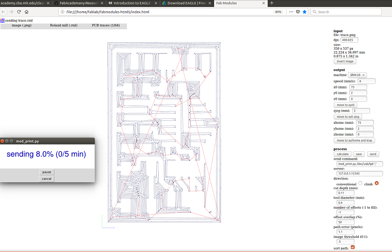
After exporting the files, I imported them into the fabmodules and then processed it for milling as shown below.
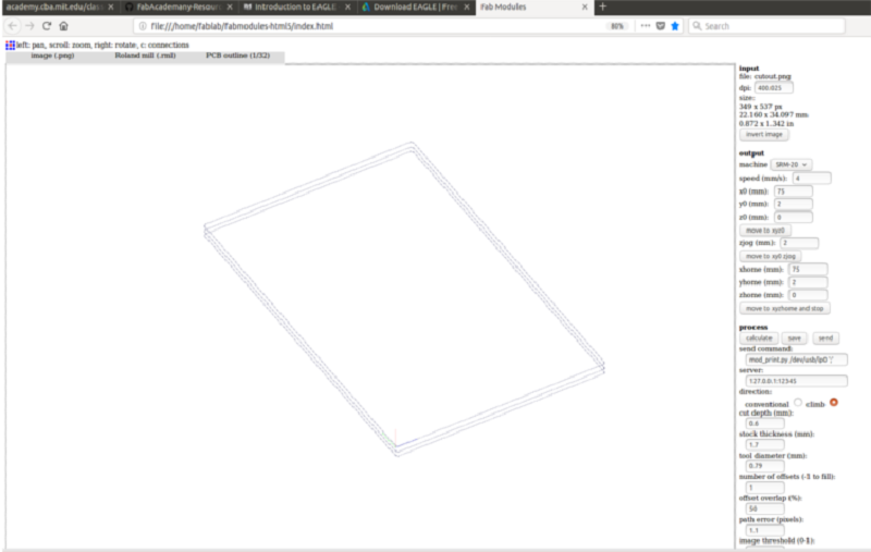
Processing cutout file in fabmodules
Processing cutout file in fabmodules
Cutting out board
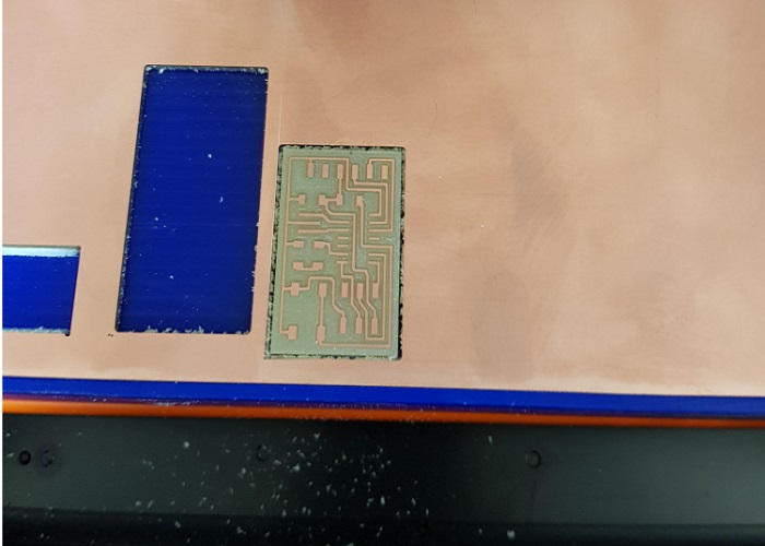
Final Cutout
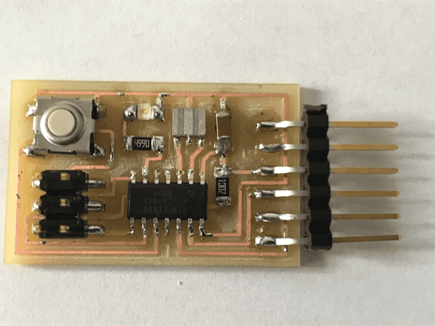
Soldering the board
I then took out the board, picked all my components and the soldered them to the board. The photos below show the
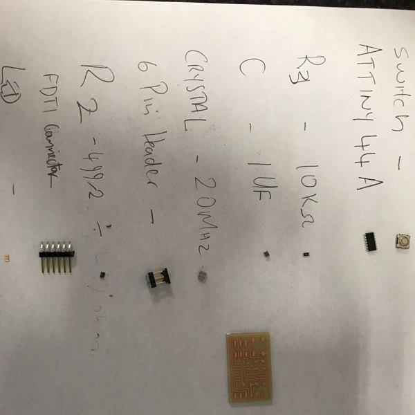
Cuomponents
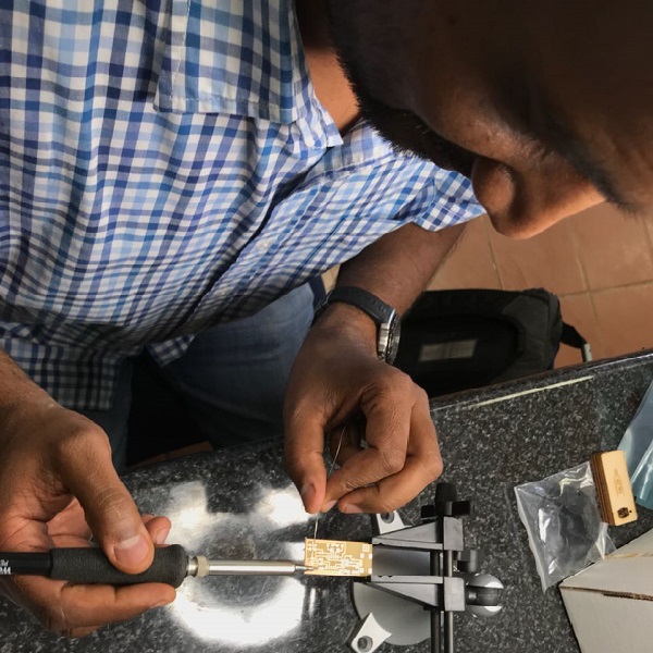
Soldering