Week 04
Computer Controlled Cutting
The assignment for the week is to Characterize the laser cutter, design something and cut it on the vinylcutter and the lasercut, and document a parametric press-fit construction kit, accounting for the lasercutter kerf, which can be assembled in multiple ways.
characterizing my Laser Cutter
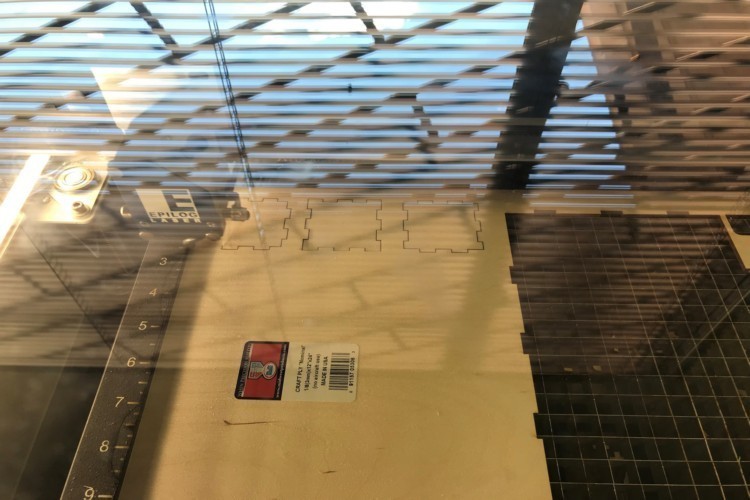
I started the week's assignment by first characterizing the kerf of the Laser Cutter. Using corelDraw, I did some laser cut test parts. I tested with five of the same shapes with varying the cutting parameters in other to get the best settings for cutting with the laser cutter. Below are photos showing the steps and process.
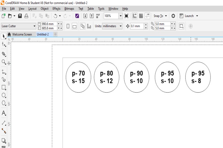
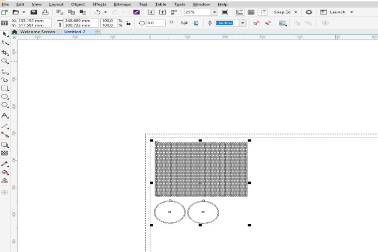
Drawing Circles with the cutting settings on them
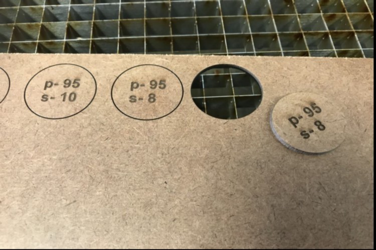
Getting the correct cutting settings ,as shown best cutting settings was Power 95 and Speed 8
Designing and cutting with the laser cutter
I decided to do my design for this assignment using SolidWorks. I decided to make a simple cube to show my understanding in making an object that can sanp fit together. It was a simple model with 6 parts, actually one would say 3 parts as each part is duplicated to form the cube. When I started my design, I knew that I needed to make sure that I take into consideration the thickness of the actual laser kerf so as to make sure it dose not become a loose fit cube. Since my design was parematric I was able to easily change the dimesions to compensate for tje laser kerf without affecting the overall dimension of my cube. I created the change of the fingers of the snap fit by, 0.1mm just to accomodate the laser kerf. Below is the 2D parts of the cube using SolidWorks.
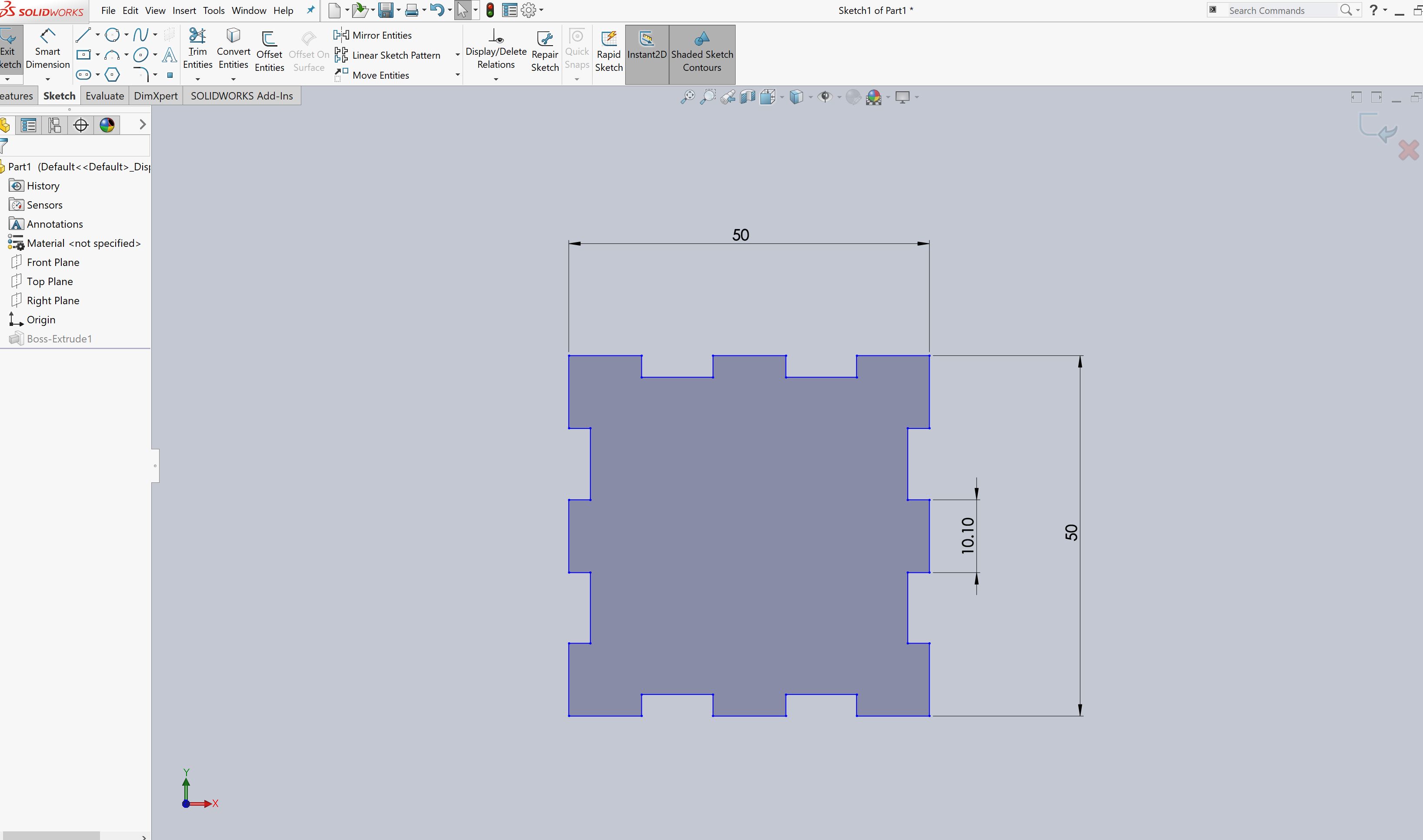
Part 1 that were designed in Solidworks
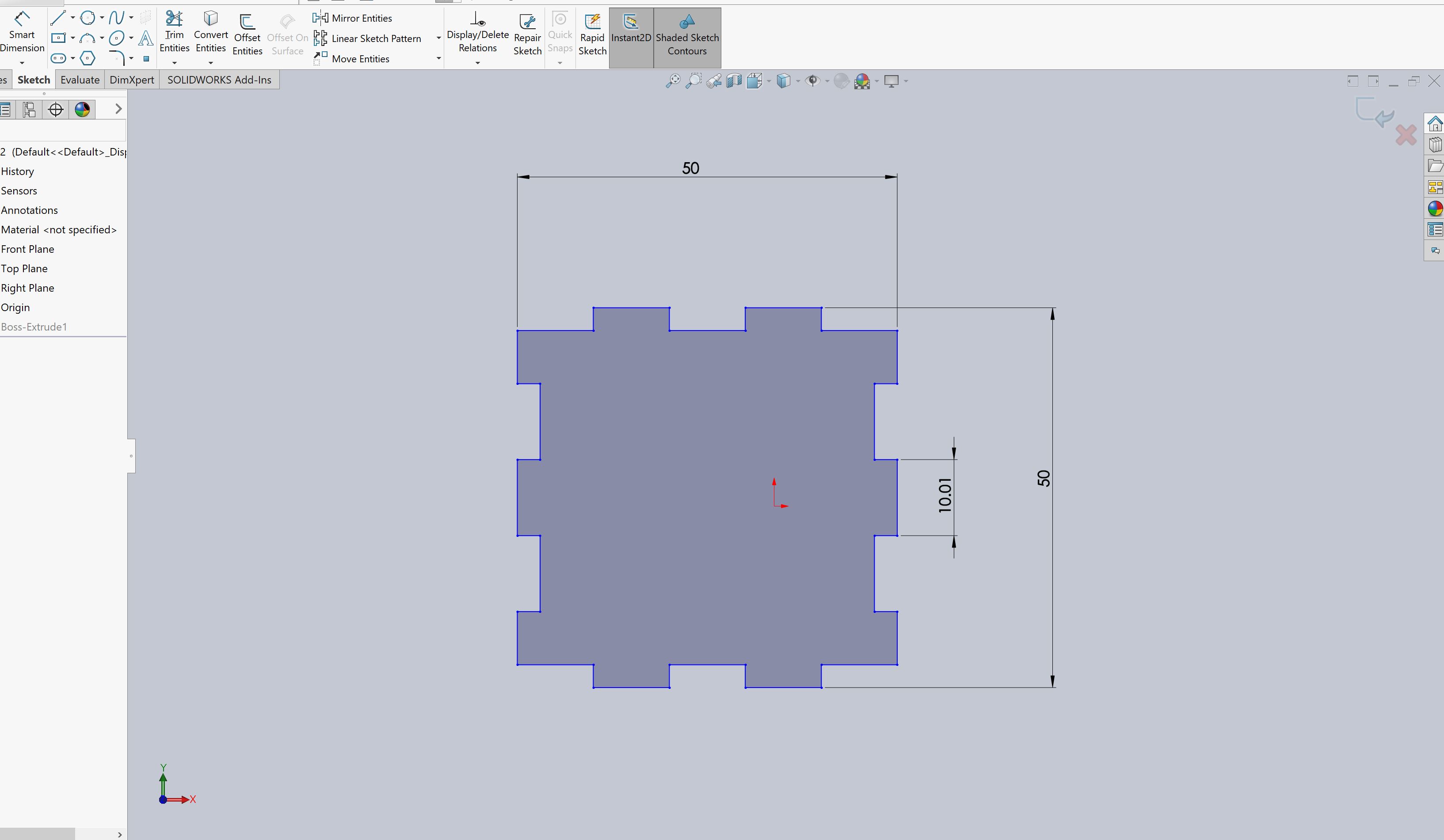
Part 2that were designed in Solidworks
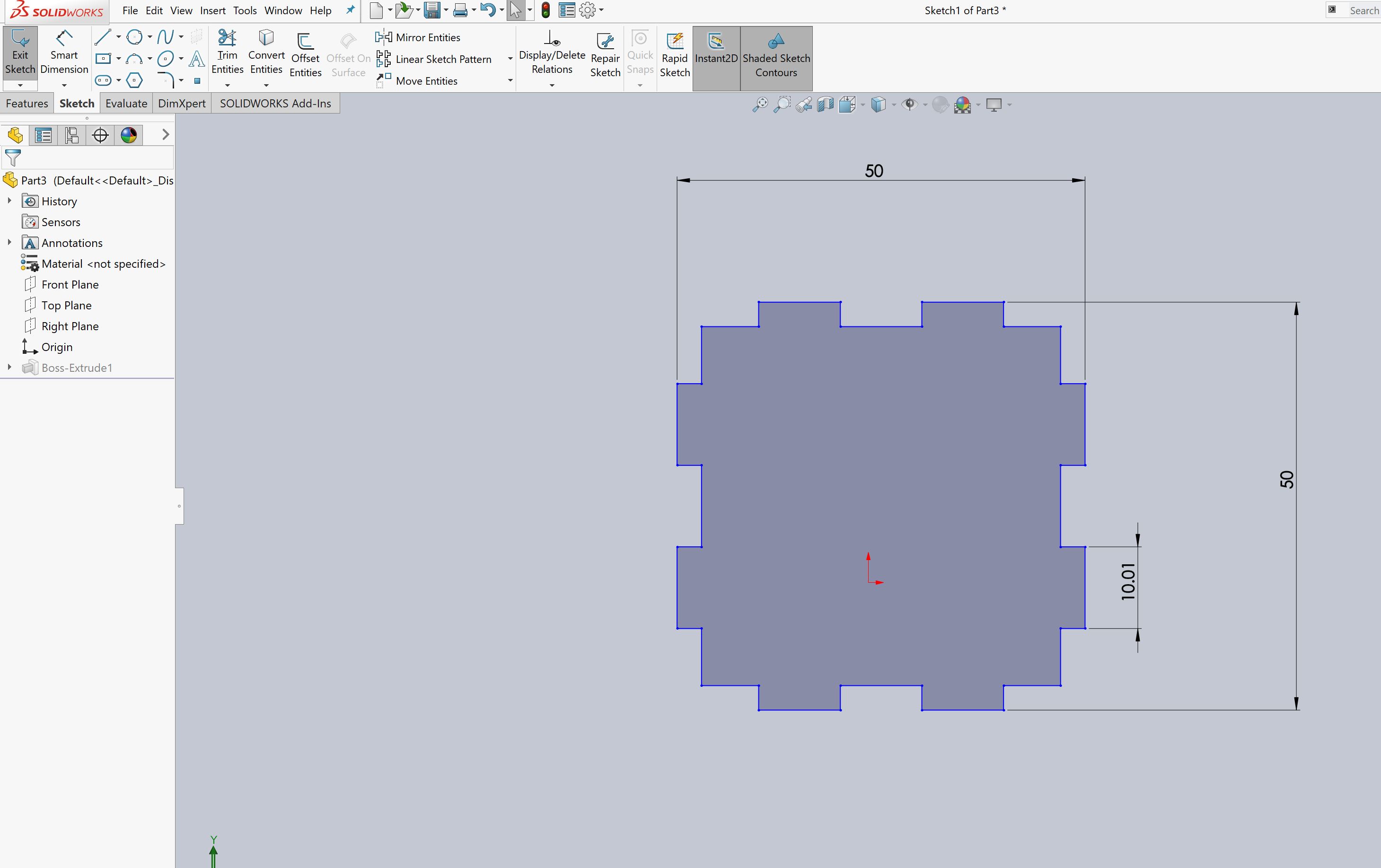
Part 3 that were designed in Solidworks
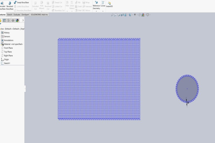
I then created DXF files of my drawing as I needed to dring my drawing from Solid works into Corel Draw, asin our Lab we cut to the lazer cutter through corel draw. I first exported from SolidWorks using the save function and choosing the file format I wanted to save it in and then creating the DXF file.

Exporting the Files from SolidWorks to DXF file Format
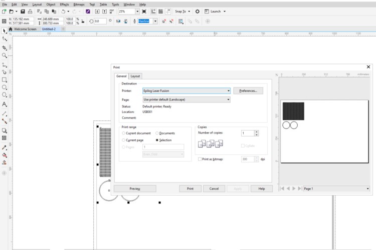
Using CorelDraw, I imported the DXF, made sure that it was Hairline so as to make it a vector lines. Using the Print Function, I set all the print parameters and sent it to the laser cutter for printing.
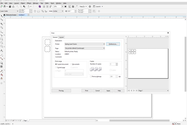
Starting the print command and sellecting the correct printer
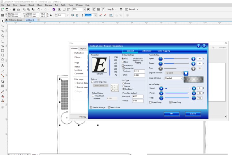
I had to selct the correct power settings and the correct speed inorder to successfully cut through my materail. and because I did the test cuts , i knew what my setting should be
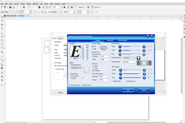
Setting print parameters and sending to printer
Cutting on laser cutter
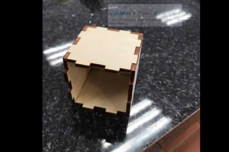
Assembling the cube
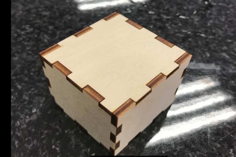
cube all Assembled , snapfit
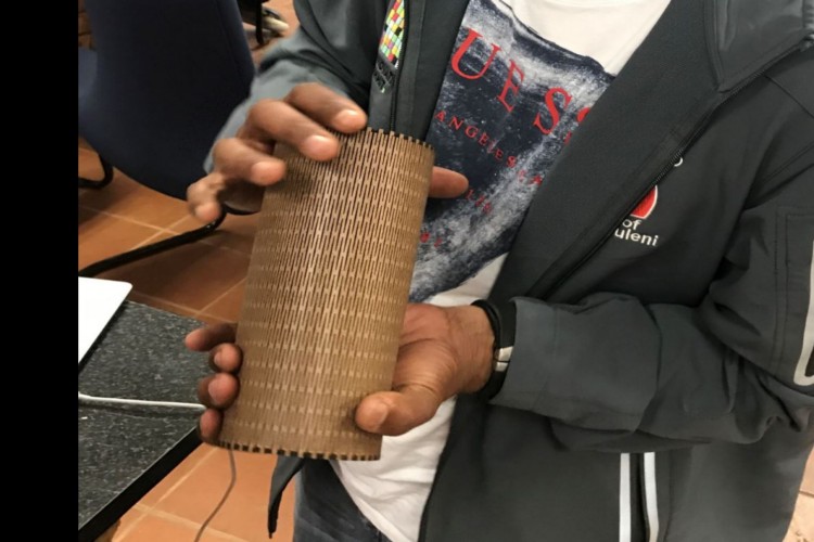
Making the wood to folds to form a canister
Folowing the presentations made , I decided that I would also try to make soemthing that would allow me to snap fit the wood but also fold the wood. So I decided to create a canister. I started my design on SolidWorks.
Parts that were designed in Solidworks
I then created DXF files of the parts and opened in coreldraw. this time, before I started to cut, I decided to do a test first to make sure that the laser cuts one time through my materail. I varried speed and power combination until I found the correct one.
Once I got the corrct settings, I imported the dxf files into coreldraw and then proceeded it to cut the design using the 3mm plywood.
Imported File into coreldraw
Set cutting parameters
Sent file to laser cutter for cutting
After sending the files to the laser cutter, I turn on the extractor and the compressor, sellected my file and started with the cutting.
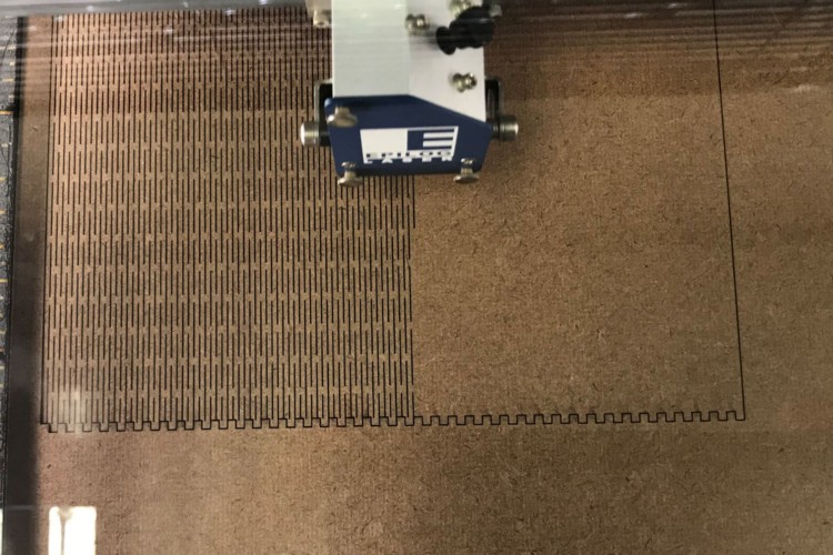
Cutting the board
Assembling the canaster
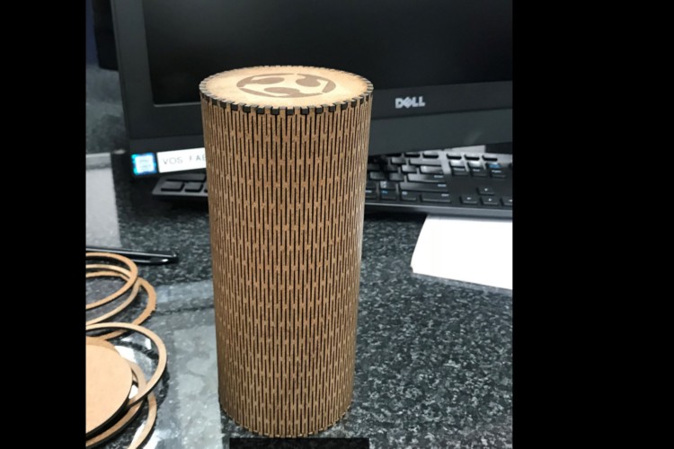
Full view
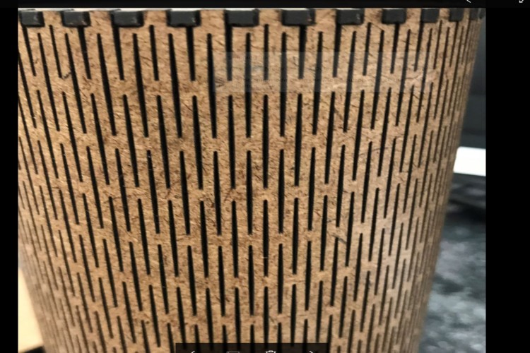
close up of side walls
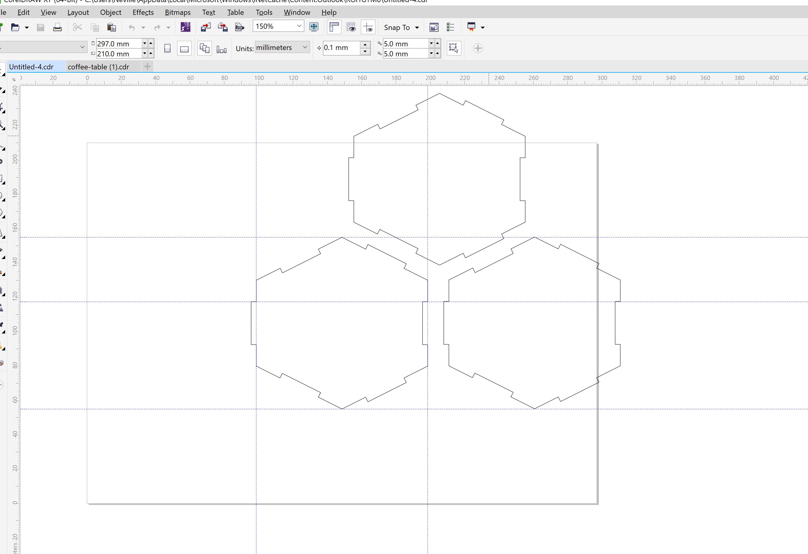
i did a quick snapfit that could be snapped in many different combinations
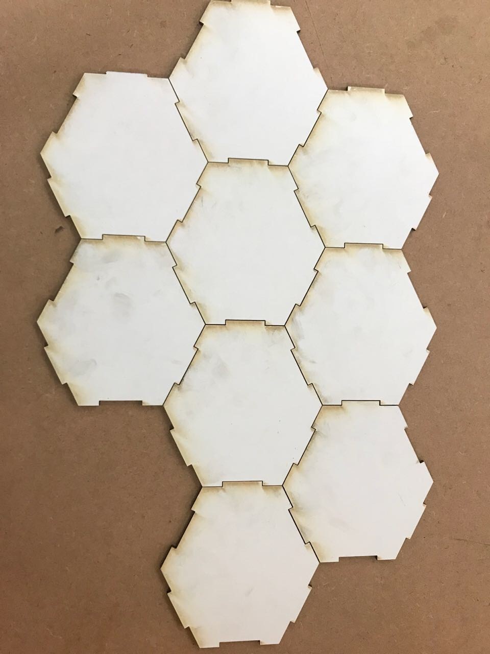
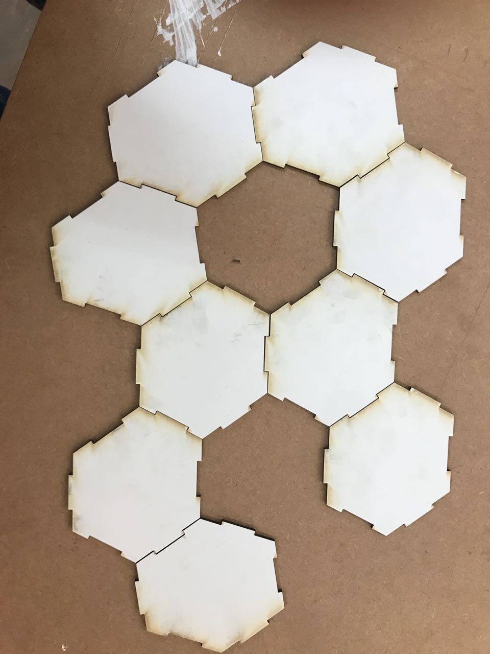
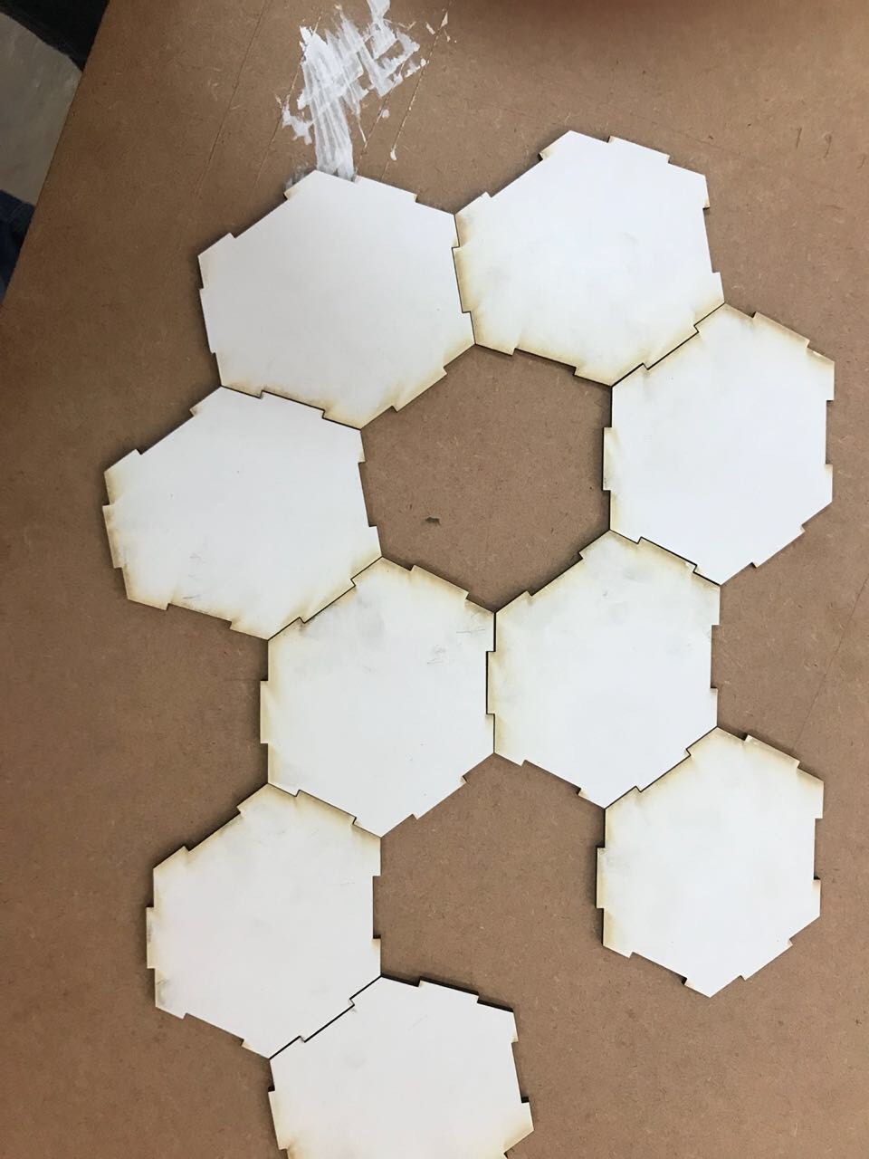
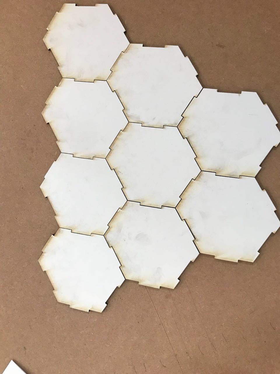
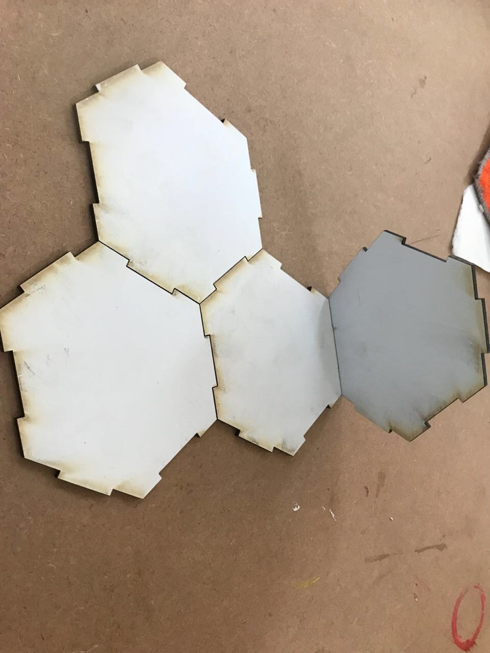
i did a quick snapfit that could be snapped in many different combinations
Using the Roland VersaCAMM Cutter
I chose to design a company logo on coraldraw and then cut it out with the roland versaCAMM and stick it on a box. After designing the log on corelDraw, I had to save it as a pdf and import it into the roland versaCAMM software (versaworks) for cutting.
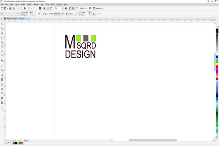
logo designed on corel draw and exported as PDF to open on Verso Software to cut on vynl cutter
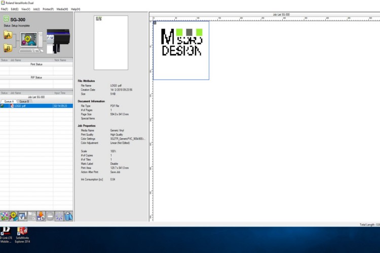
Importing file into VersaWorks
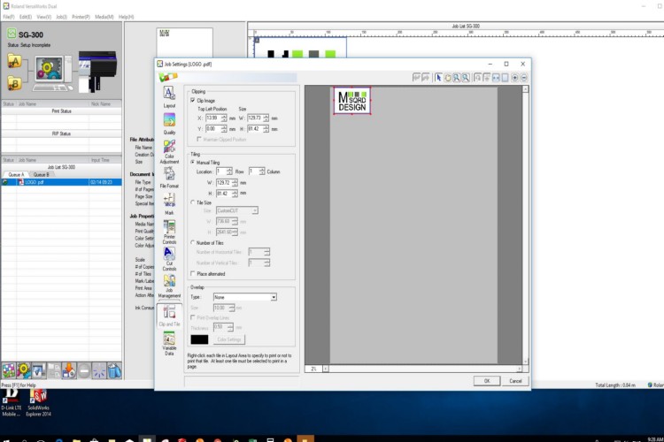
Setting print parameters
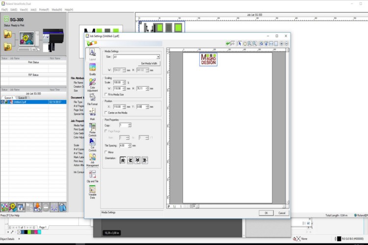
Accepting the setting and printing
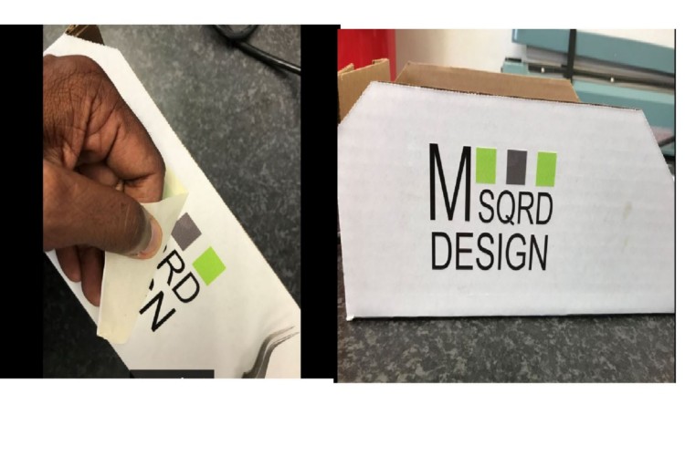
transfering the image onto the board
After printing the logo onto the vynl, I then removed all the unwanted parts using a tweezer and then used transfer tape to transfer the Logo onto the box.
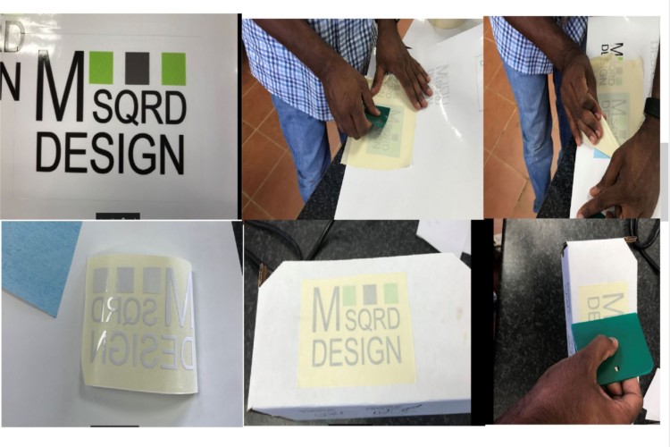
Transfering the vynl