Week03
Computer Aided Drawings
Following the lecture on computer aided drawings, I was impressed by the number of cad packages that existed. From the long list of softwares, I decided to tried my hands on the following CAD Pakages; Corel Draw, Inscape, Rhino and SolidWorks. It happened that, for the 2D CAD softwares, I liked Corel Draw more than Inskape, but I think my choise of liking the CorelDraw to Inkscape is because i had the student version of corel draw and have already had much practice with it.
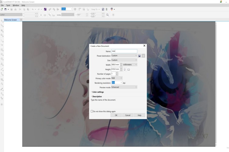
Opening corel Draw and setting the parameters for my drawing
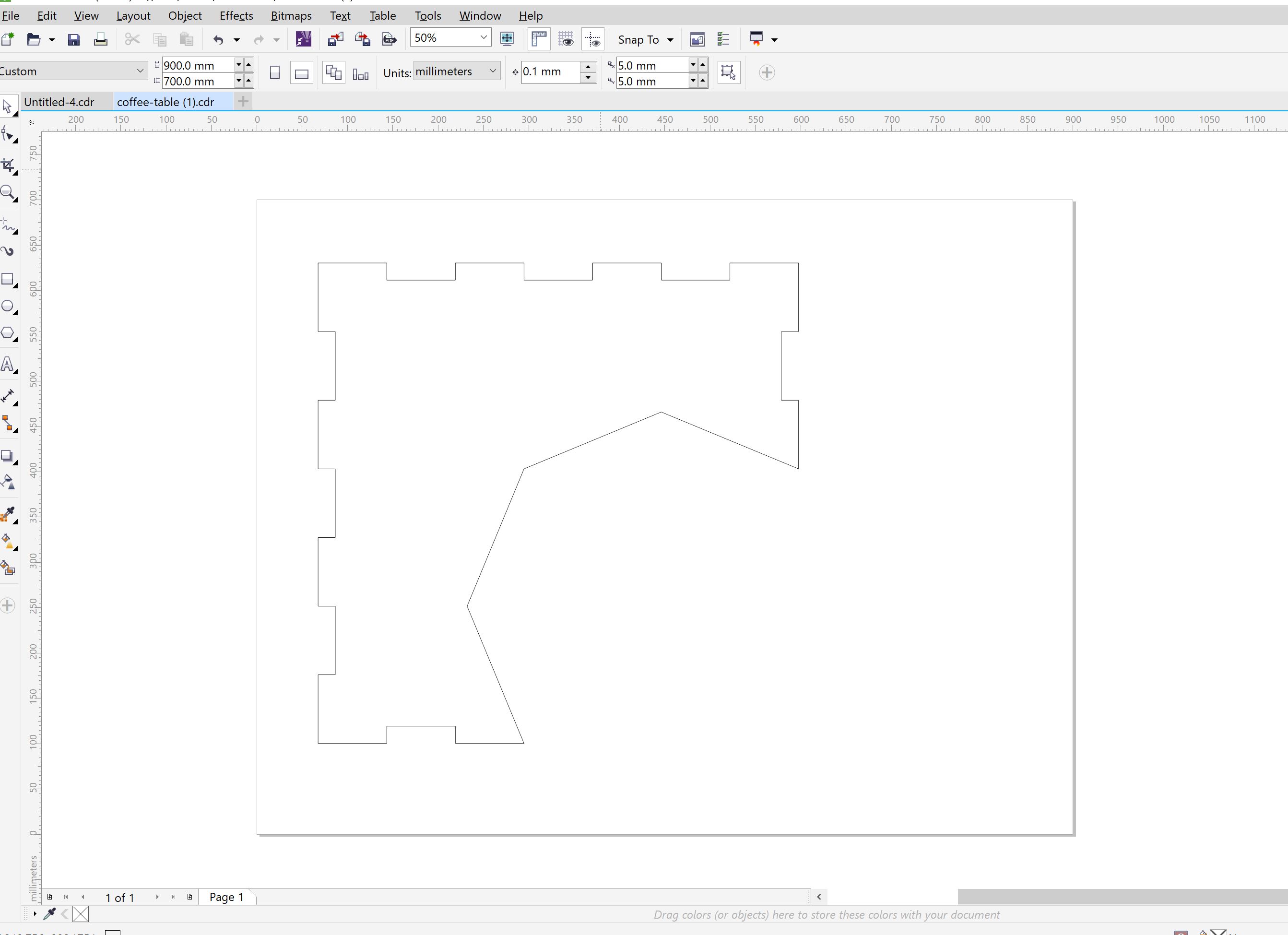
Drawing part 1
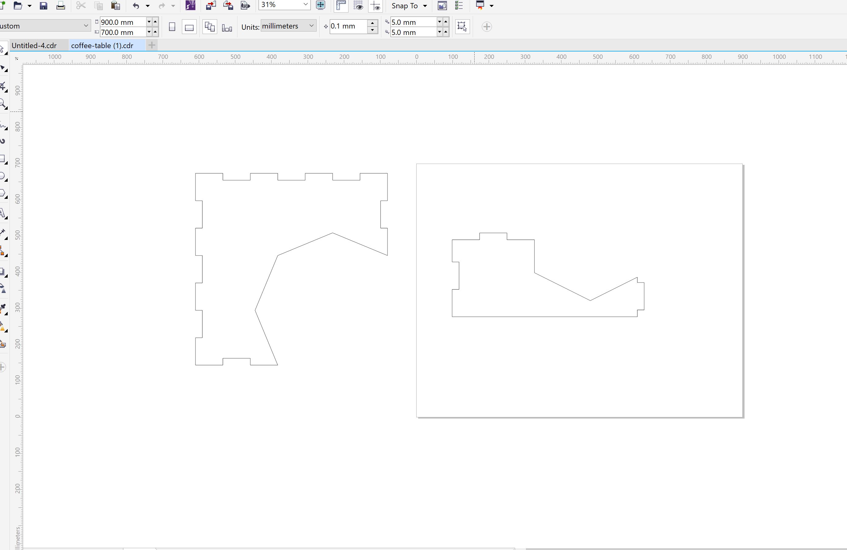
Doing the same process, I have drawn each part , one by one
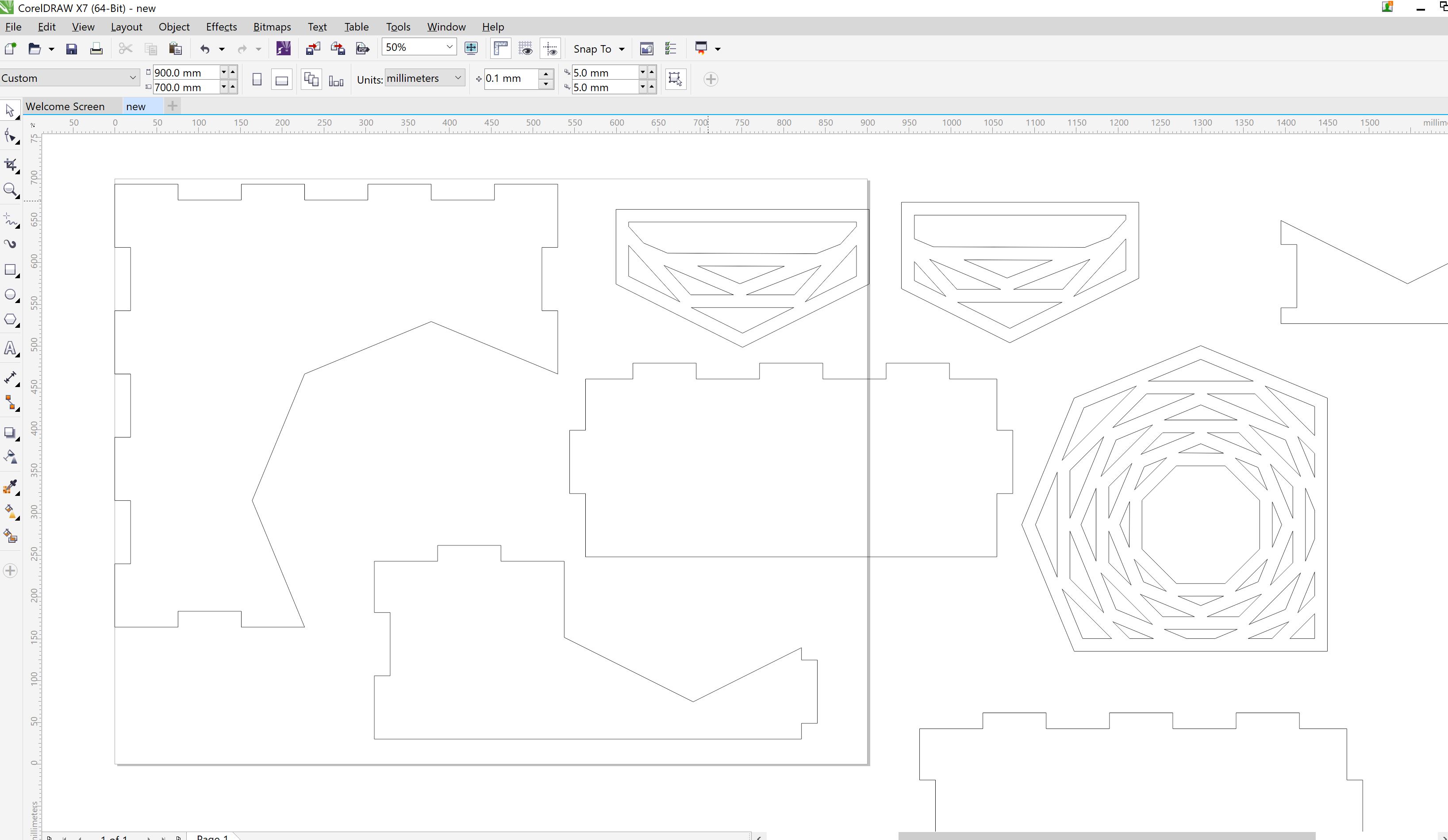
after all parts were drawn
To download corel draw files click here
For the 3D CAD package, I decided to use one that is both 2D and 3D and would allow me to do parametric designs. I chose to use Solidworks, for the simple reason that I have used it before and am more familiar with it than most of the other 3D CAD programs.

Solidworks
Using Solidworks
Using solidworks, I opened a new file, and chose the option of Part. Solid works allows one to design each part and then assemble the parts together to give you a final product. To work efficiently I had to first design my coffee table on a piece of paper, this allowed me to see what parts I need and also the dimensions of each part. I started with the top part of the coffee table first, once opening a new file and selecting parts, I had to choose a plane to work on, which I chose the front plane and then continued to draw my coffee table. The tools in solidworks is very simple and similar to any other CAD software. Assignment for this week was to show one’s ability to use a the 2D and 3D software. I am not ready to start my final project as I am still conceptualizing the processes that is needed , thus I looked at making a project that would be able to display the skills needed and would be of value to me. I looked at a very simple design of a coffee table, which would show the 2D designs and then also the 3D design of it and be able to render it finally. The design should also show the snap fit of the parts. My idea was to make a coffee table with a plant pot on one corner, which would make it a bit unique.

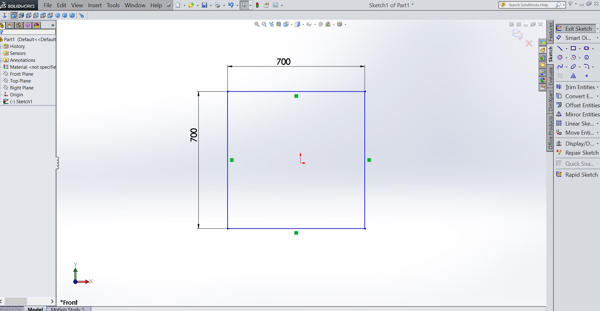
Opening Solidworks
Starting to Draw on Solidworks
The coffee table I decided to design have an overall dimensions of 700mm x 700mm x 300, with a hole on one corner that would allow for a potted plant to fit. I made the snap fit to be parametric, as it would allow me to change the wood thickness when needs be, without any hassle. Once I have completed the drawing of the top part in the 2D plane, I used the extrude feature and extruded the 2D design into 3D modle. My material thickness being 19mm pine. I followed the same steps and designed each part of the coffee table. I used the extruding function and extruded each part to the materail thickness. the photos below shows the drawing steps.
Steps in drawing the parts for the table.
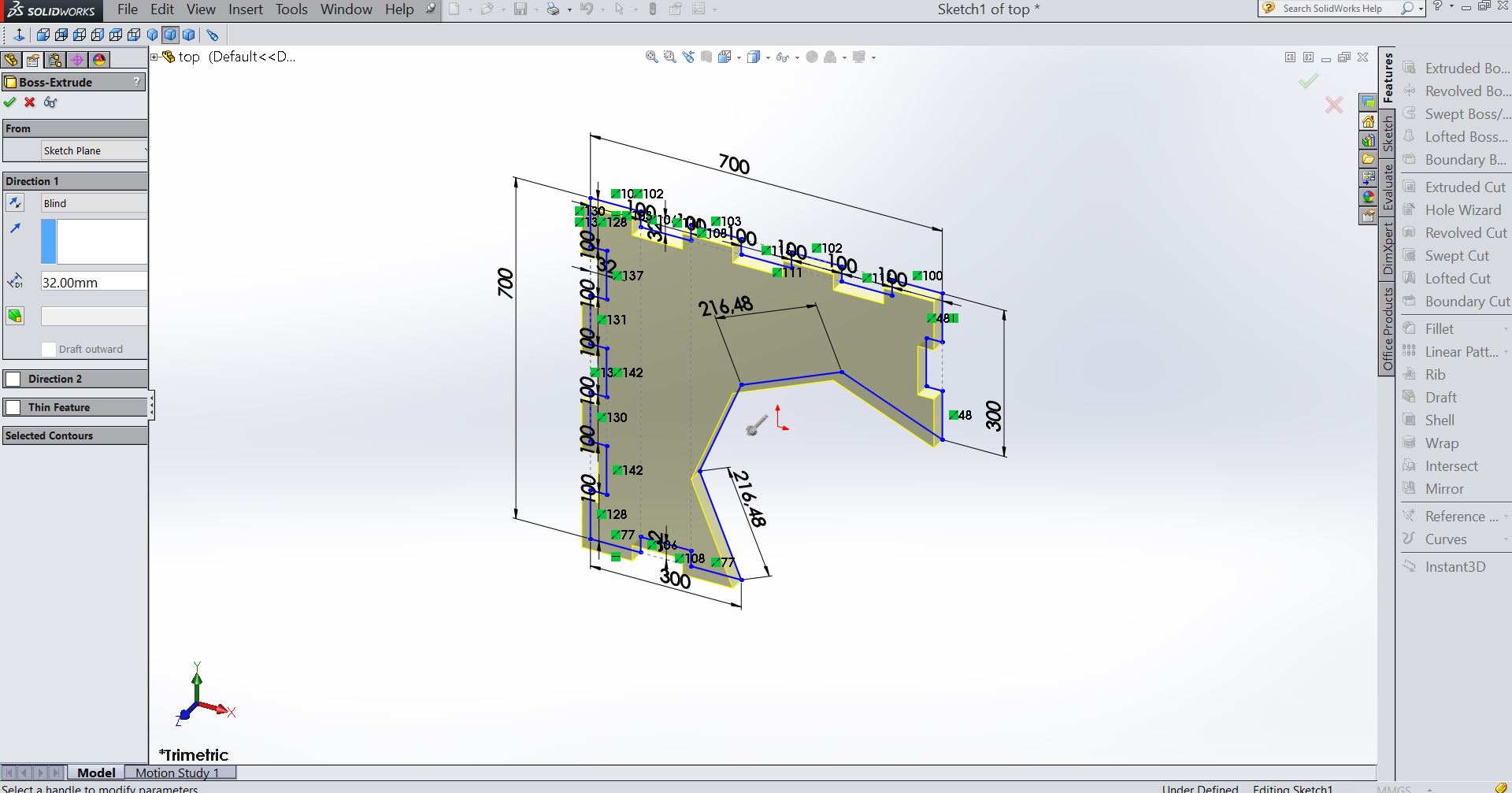
Steps in drawing the parts for the table.
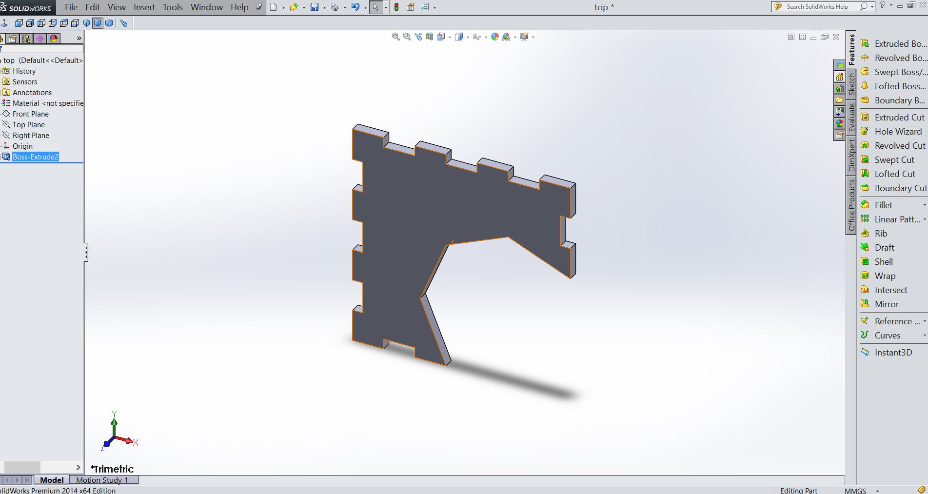
Steps in drawing the parts for the table.
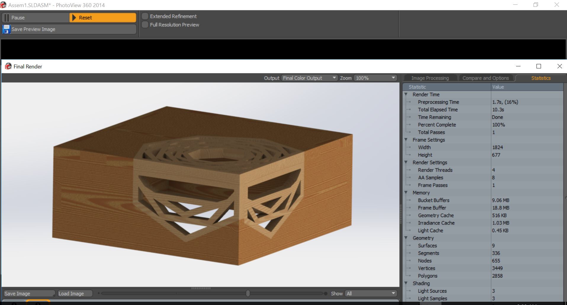
Once all the parts were desgned and extruded , I opened a new page but this time selected assembly. i used the mating tool and started the assemble part by part , and when i was completed , i decide to add a bit of texture on the table and then used the rendereing tool to add texture and rendered a view of the finish product.
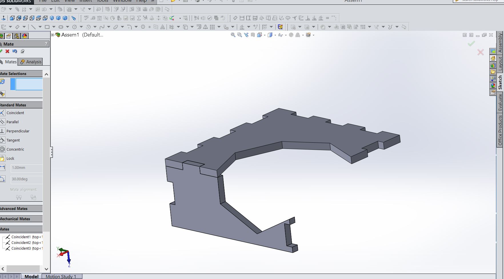
Assembly of Table using the mating function in solid works