Electronic Production
This activity has put my mind back several years ago because this was an everyday activity back at university days.
Although the passive components remain the same, nowadays SMD encapsulate is more use than before.
Several years ago the use of lithography and ferric chloride was very common. However for these activity we decided to use the milling process.
Group assignment
Our team was very exited to proceed with these activity, for the majority of us it was the first time they make a PCB and solder also.
It was challenging, we did it. Each of us was able to build its own board, solder and program it.
Assignment:
The assignment consist of:
- Characterize the specifications of your PCB production process
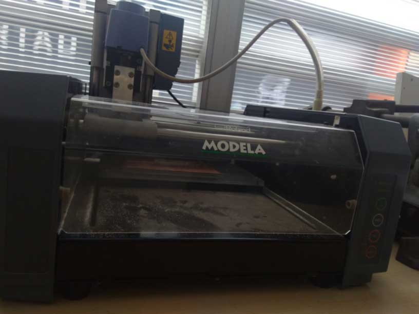
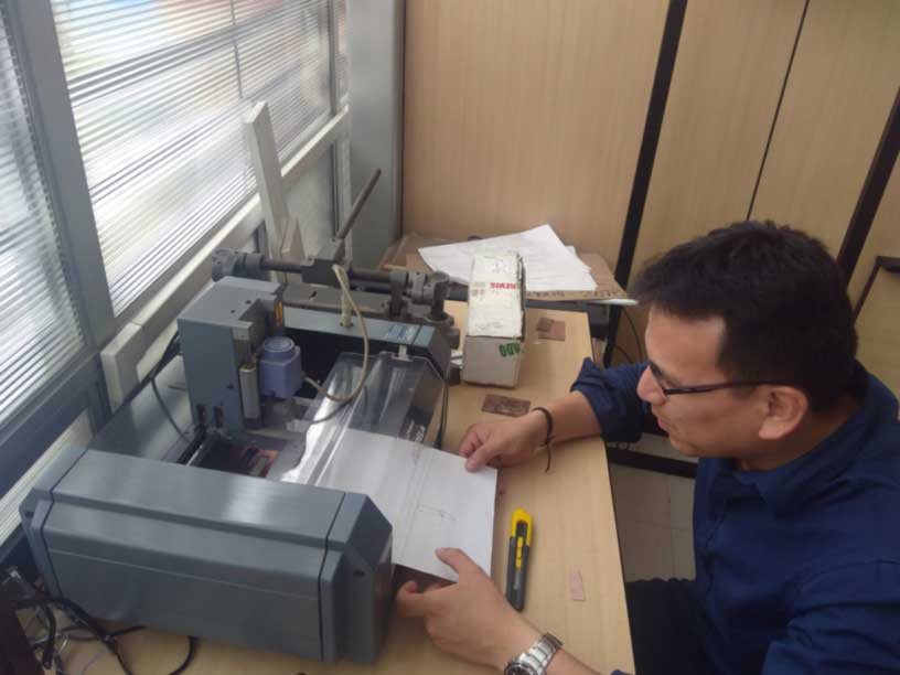
Characterize your PCB router machine
Roland MODELA 3D PLOTTER MDX-20
TECSUP Lab has these router engraving machine: MODELA. Some important things to consider prior the put it on operation.
At the previous link you may see all the information, drivers and manual for its normal use.
In order to build a PCB some important steps were taken:
- Define the correct drill for router: cutting, router.
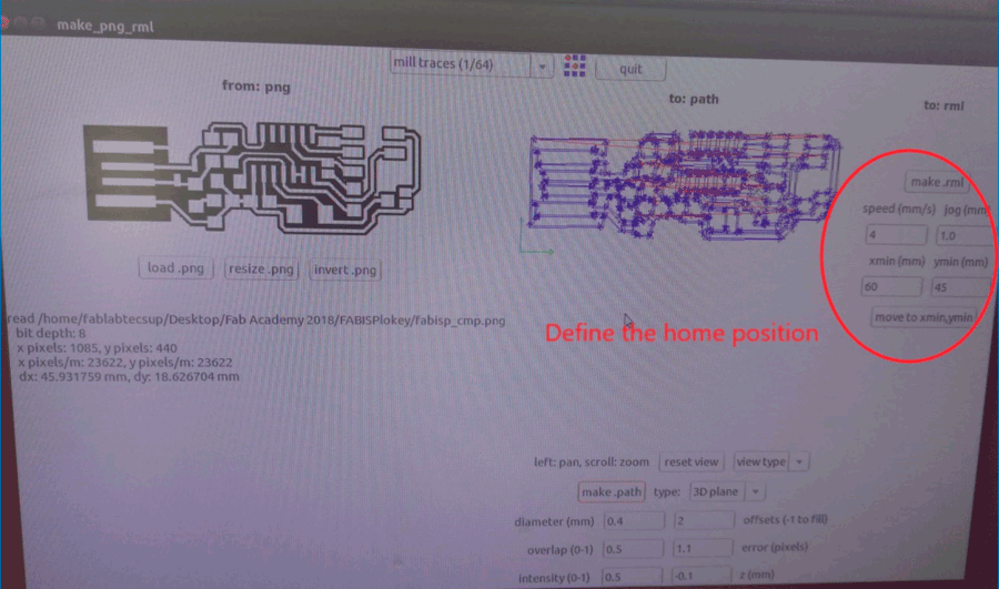
- Setting the initial position for Roland router.
- Route and mill
Define the correct drill for router
In order to set the correct position, we need to define en 0 position, it is possible to do it by setting its x and y position.
Also the Z axis is the most important part to set it, otherwise you can break a tin. We had a couple broken tins of 1/32" because the Z was not set properly.
Setting the initial position for Roland router
In order to improve the space of the copper table, we set the position manually
Route, mill and cut out the copper board.
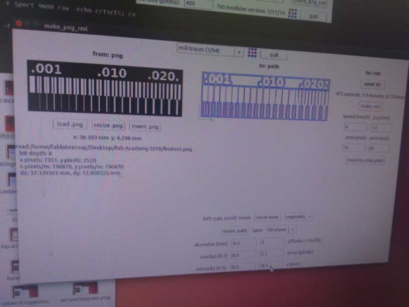
The following parameters were use for milling and cutting:
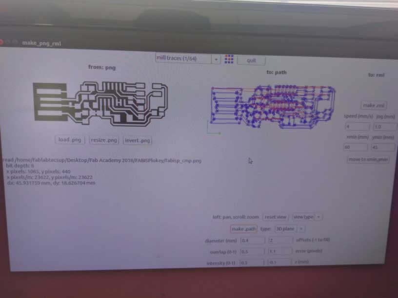
Milling parameters
Please select the option mill and traces 1/64
| Parameter |
Value |
| diameter |
0.4 mm |
| overlap |
0.5 |
| offset |
2 |
| Z mm |
-0.1 |
| intensity |
0.5 |
| error (pixel) |
1.1 |
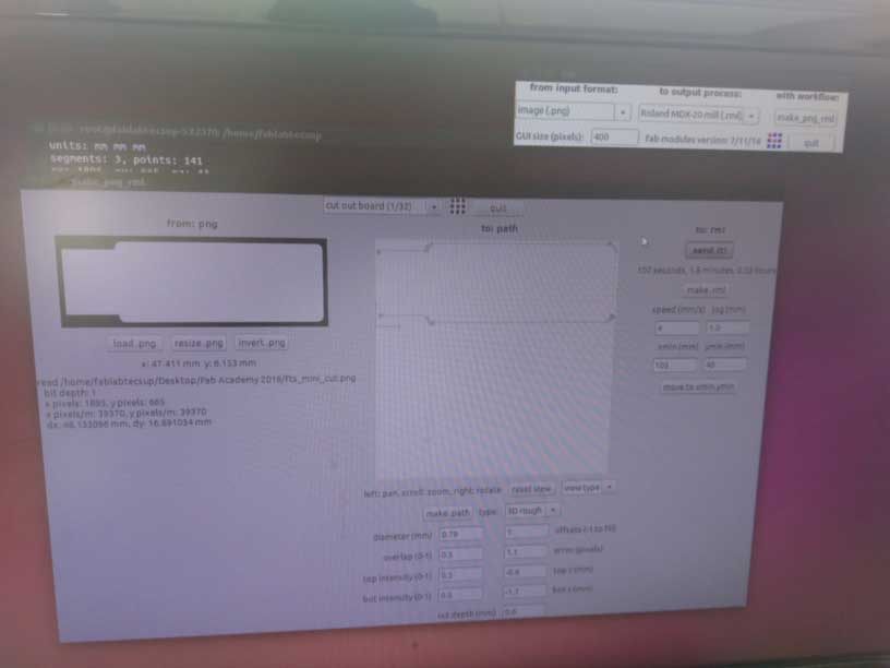
Cutting parameters
Please select the option Cut out board (1/32)
| Parameter |
Value |
| diameter |
0.79 mm |
| overlap |
0.5 |
| offset |
1 |
| top z mm |
-0.6 |
| bot z mm |
-1.7 |
| top intensity |
0.5 |
| bot intensity |
0.5 |
| error (pixel) |
1.1 |
| cut depth |
0.6 |
Individual assignment
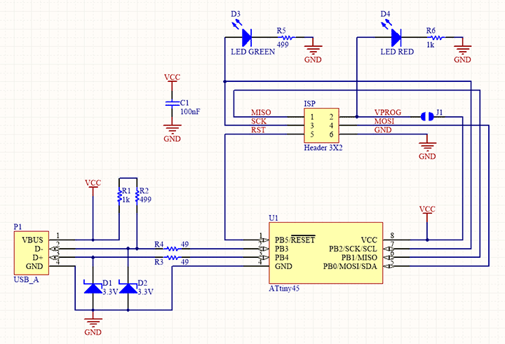
The assigment was to make a in circuit programmer (ISP) by milling the PCB.
For these activity I chose Brian model with consist of a ATtiny45 microcontroler from Atmel, nowadays from Microchip
The needed materials are:
- ATtiny45 or ATtiny85 (1)
- 1kΩ resistors (2)
- 499Ω resistors (2)
- red LED (1)
- green LED (1)
- 100nF capacitor (1)
- 2x3 pin header (1)
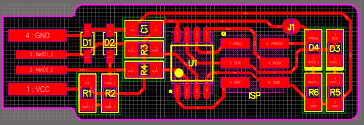
The schematic and pcb board are:
All the group activities learned at the previous task were important and these one such as:
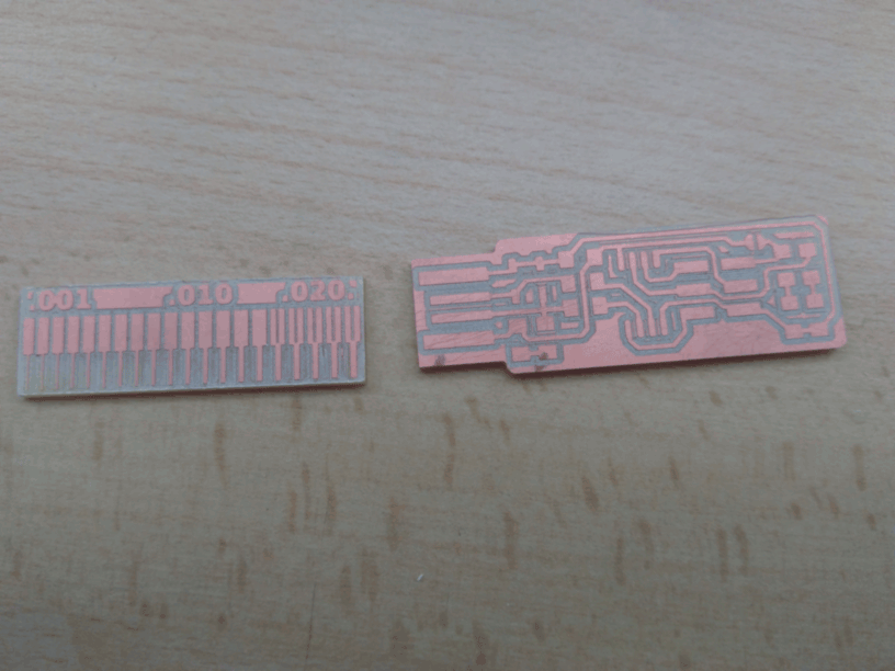
- milling
- cutting
- soldering
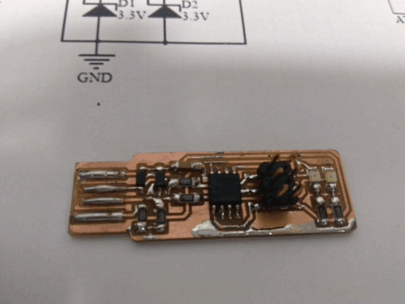
Milling and cutting parts were easy, you may see at the following images
Several years ago I used to solder, however these days SMD are widely used. It was not so hard but for sure the last solder elements had
a better quality than the previous one.
Let me share you how the FabISP had been made.
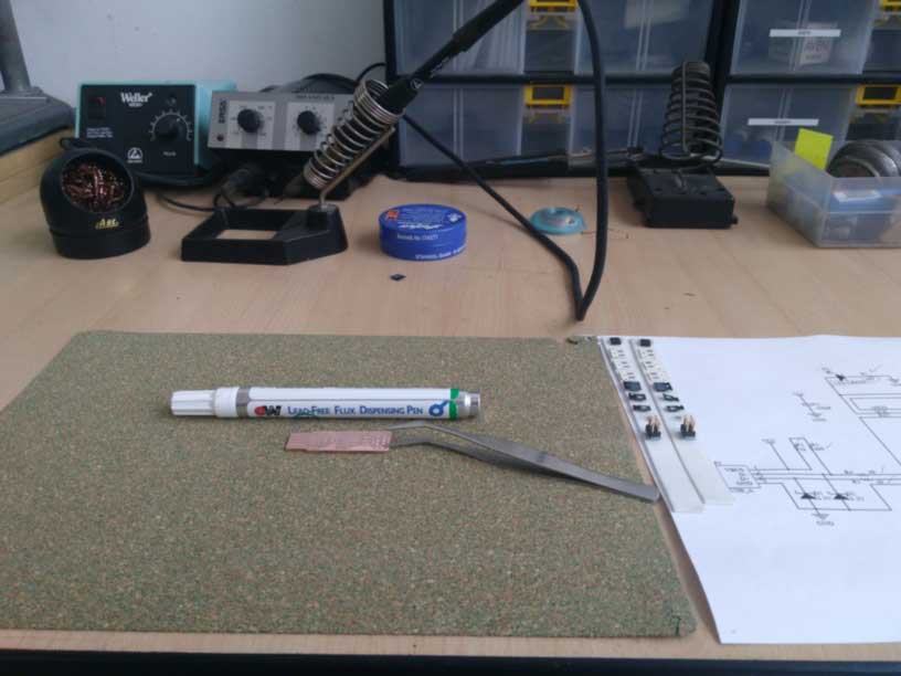
Use the flux just on the component you are going to solder.
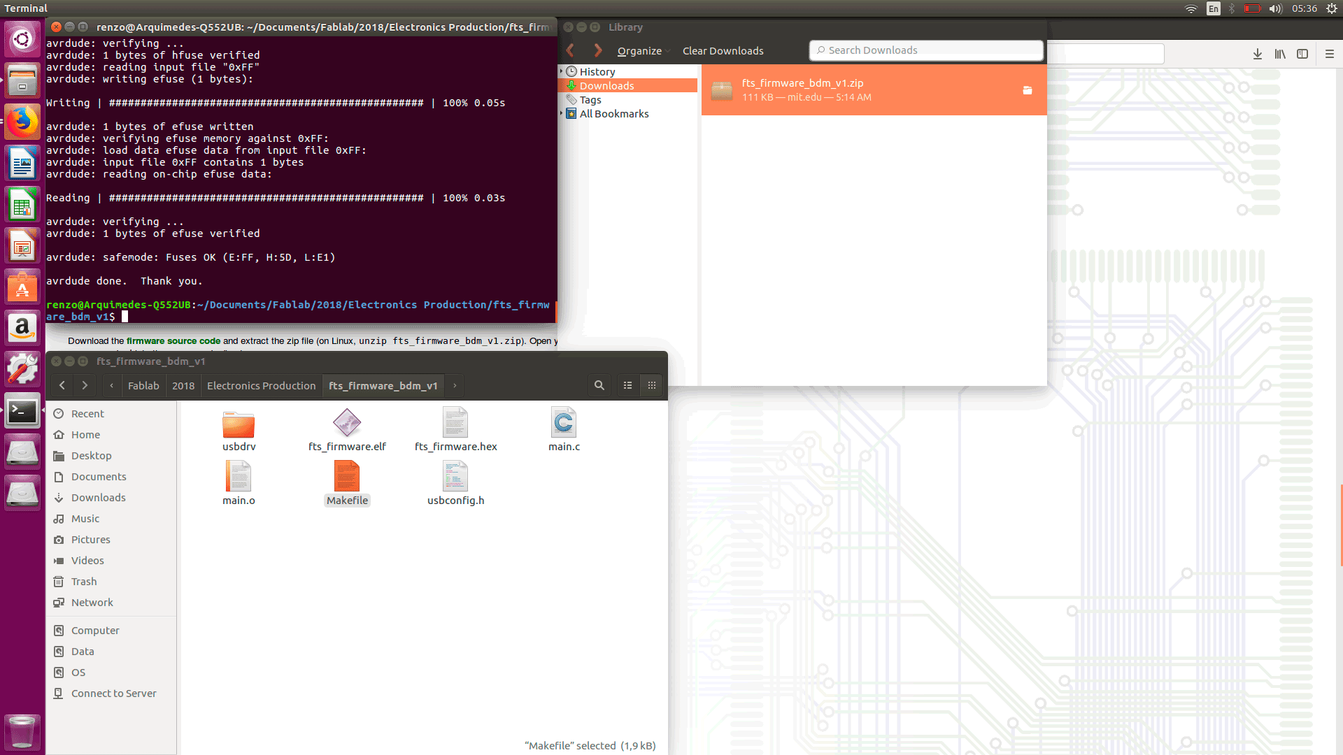
These last part of the activity was done with a Linux machine. I follow all the steps for it at Brian model
It consists of three parts:
- Installation of AVR software
- Edition of the Make file
- Program of the microcontroller
Edition was most important part, if we choose the wrong programmer it will never load the firmware on the Microcontroller. I chose: avrisp2
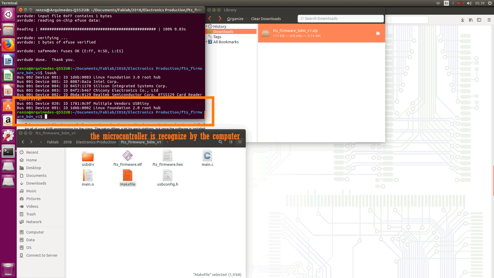
After that you may be able to run the make fuses command, if everything is successful the rstdisbl command.
If everything is correct you may disolder the bias and see if the FabISP board is recognize by the computer.