
Computer aided cutting
Electronics Production
I started this week task by learning about Roland SRM-20 and how to use it, our Roland mill is quite new. I started with interfacing the Roland with the computer, and by using a simple interface (Fabmodules) I was able to upload the PNG file for the traces and the cut.
Starting from choosing the input format (.png) then the output format (Roland mill), and identifying the process (Traces or outline) I was able to start the first step into PCB milling.
In the process, you can dientify the cut depth, and the number of offset, my first trial I used 4 for the offset and the bit was worn out so the mill was not satisfying. Note that I used 0.1 cut depth for the traces and 0.6 for the outline
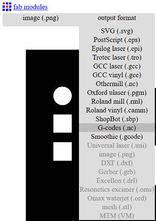
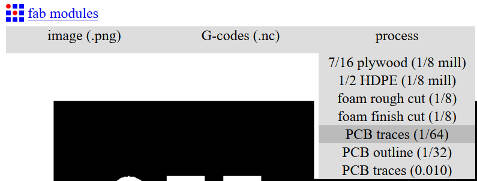

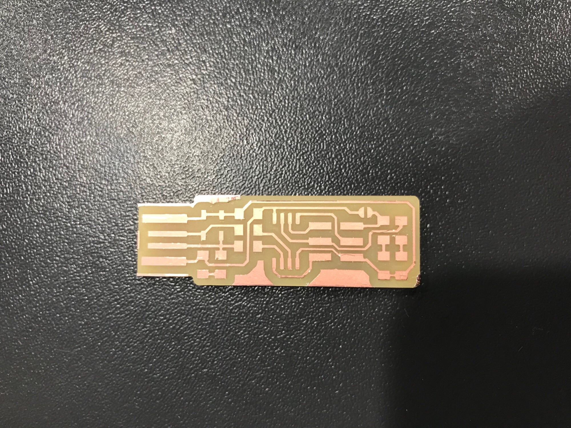
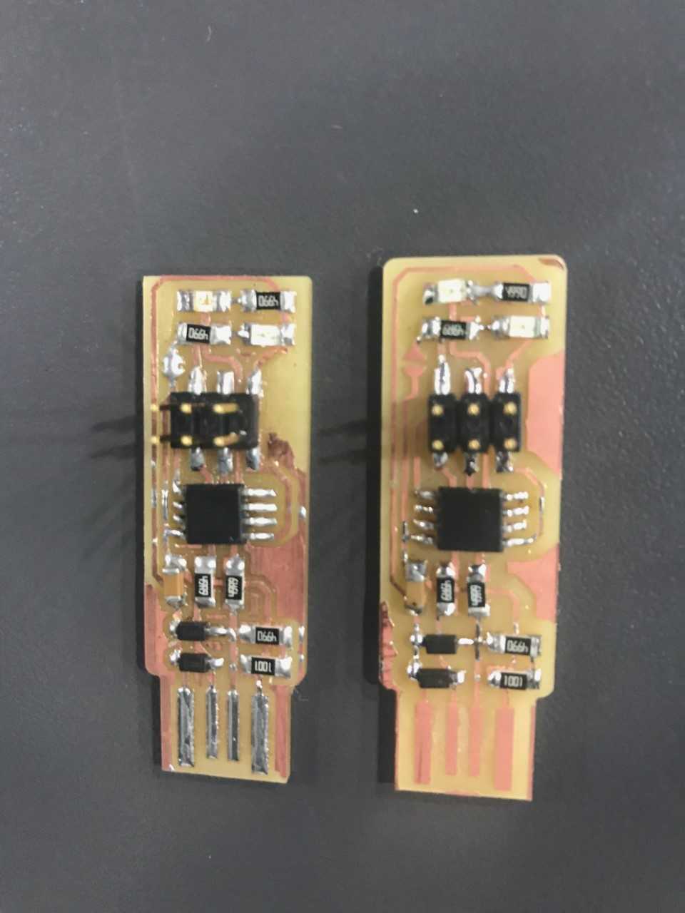
I then started with the milling process, I changed the bit to 1/64 for the traces first and then switched to 1/32 for the outline. Using the Vpanel, I identified the x,y origin first then manually set the Z offset. I have some expereince with soldering so It took me about 10 mins to solder the componenets on the baord, so I could See below pictures for
As for programming the programmer, I started with installing the development enviroment, I followed Brian steps to download the firmware source code
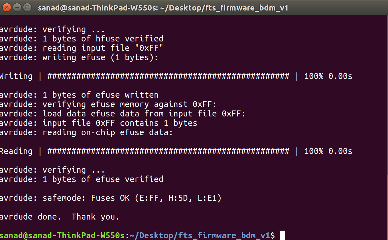
we need to connect another programmer, It should be noted that the boards are oriented in the same direction. Then we need to enter make flash on the terminal. This will erase the target chip, and program its flash memory with the contents of the .hex file . We should see several progress bars while avrdude erases, programs, and verifies the chip. After flashing we need to set the configuration fuses, which is done by entering make fuses on the terminal. This will set up all of the fuses except the one that disables the reset pin. Next we need to check the USB connectivity. This is done by typing lsusb in the terminal, which will list USB devices. And if we should see a "Multiple Vendors USBtiny" device, it worked correctly, and it did work for me right first time itself. Now there are two final steps left to turn your board into a programmer that can program other boards. First, we need to change the bit that will turn the ATtiny45's reset pin into a GPIO pin. Once again, this will disable our ability to reprogram this ATtiny45 in the future, which is why we wanted to make sure everything was working before doing this. Connect the ISP programmer to the board one more time, and run make rstdisbl. This does the same thing as the make fuses command
