
Electronics Design
This is the most fun Week for me . I have learnt a lot of things in the past about PCB design.The assignment this week aims to form a basis on how to design schematic and PCB as well as programming microcontrollers.The key method I will use this week is by using the PCB milling machine (Roland SRM-20)to produce the board
The two software that I used this week are the PCB artisit and eagle. I have found the PCB artisit to be user friendly but has a lot of limiaation on the number os layers, size of the PCB and the design rules option. while the eagle has a lot of features that make your design more efficient.
Eagle software is widely used in Fablabs and for hobby Electronics and beginners. below is a link to tutorial on how to use eagle to design PCB
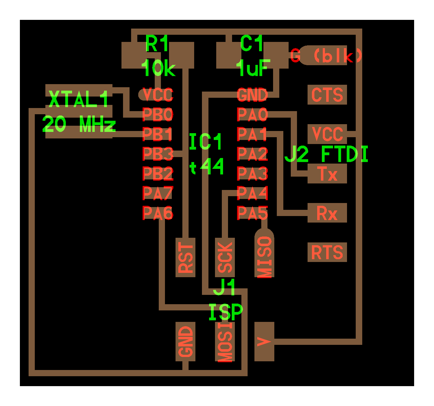
linkI started this assignment by studying the orignial hello board, The design process for most electronic circuit boards begin with a schematic which indicates in symbolic form the main electronic components and how they are connected together. This forms the basis for the printed circuit board (pcb) design: the physical representaton of the circuit. The original HelloWorld board did not have a schematic so using the original circuit layout and parts list a schematic was drawn up using Eagle PCB design software.
We decided the resistor value for the led using ohm and kirrchuf laws, I used the 1K ohm resistor for the LED v=IR
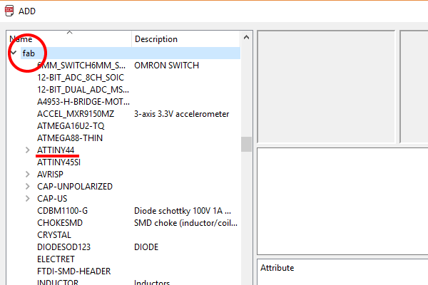
After Install Eagle I download the fab library (a list of electronic component that any FabAcademy student must have
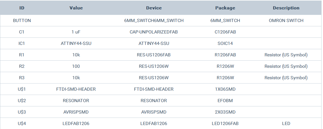
Below is the list of componenets
Schematic

With the schematic completed the next step was to move to pcb design. From the Eagle schematic tool bar the switch to board button was selected. This created a pcb and placed the components outside the board
PCB
Design Rules
The pcb parts are placed on the board and the electrical connections routed to them. Before this can happen the design rules for how that particular board will be laid out need entered into the CAD software. The design rules ensure the printed circuit board can be made and take into account the manufacturing process, which in this case is isolation routing using Roland SRM-20 and a 1/64 inch end mill. Given the end mill diameter of approximately 16 mil this will determine the minimum route seperation between adjacent traces and component pads. The trace width needs to be decided also : too wide and the board will be difficult to route, too narrow and the milling process may lift traces. Previous board designs that were manufactured using the Roland SRM-20 used a trace width of 12 mil so this value was chosen for the HelloWordNC board.
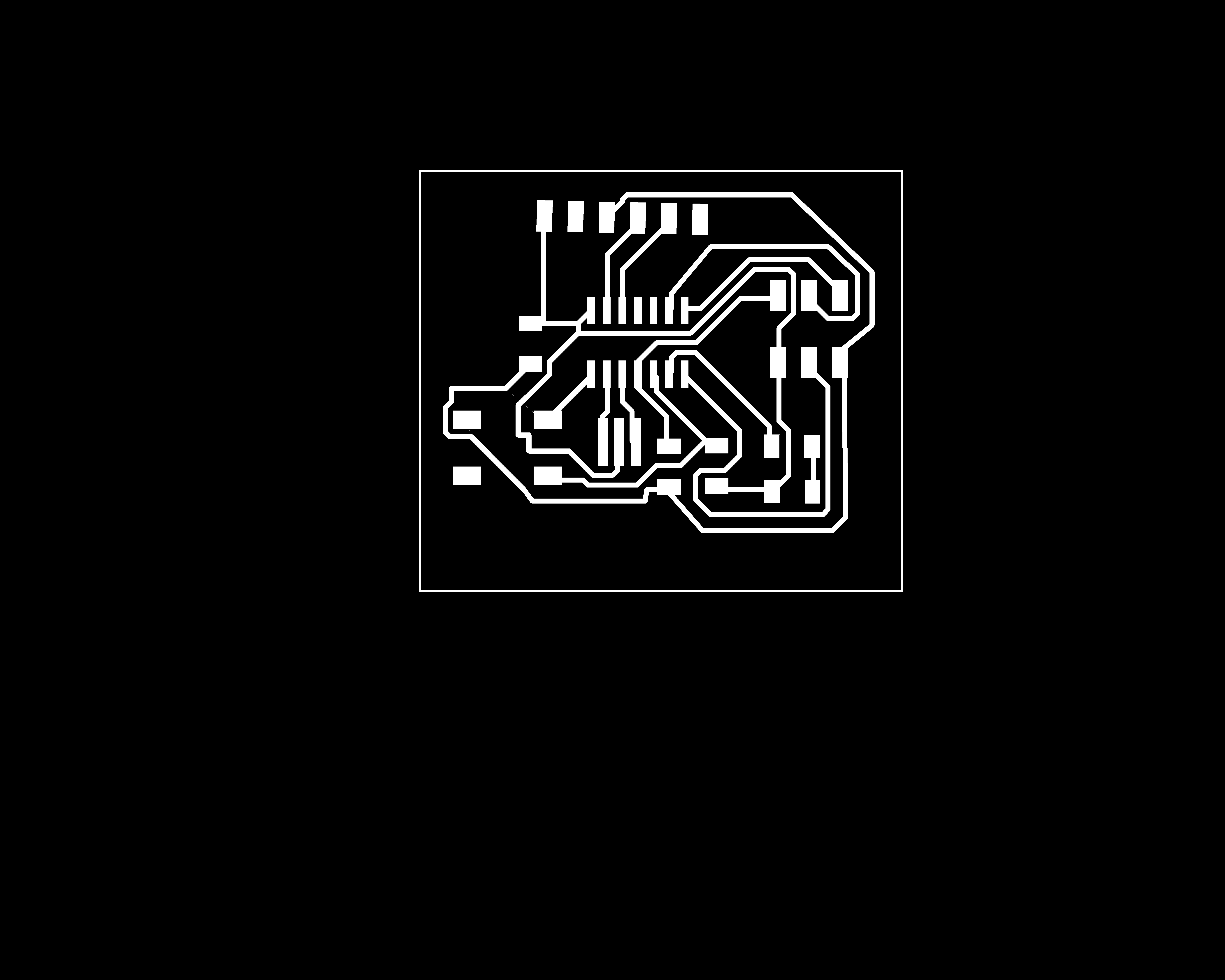
.jpeg)
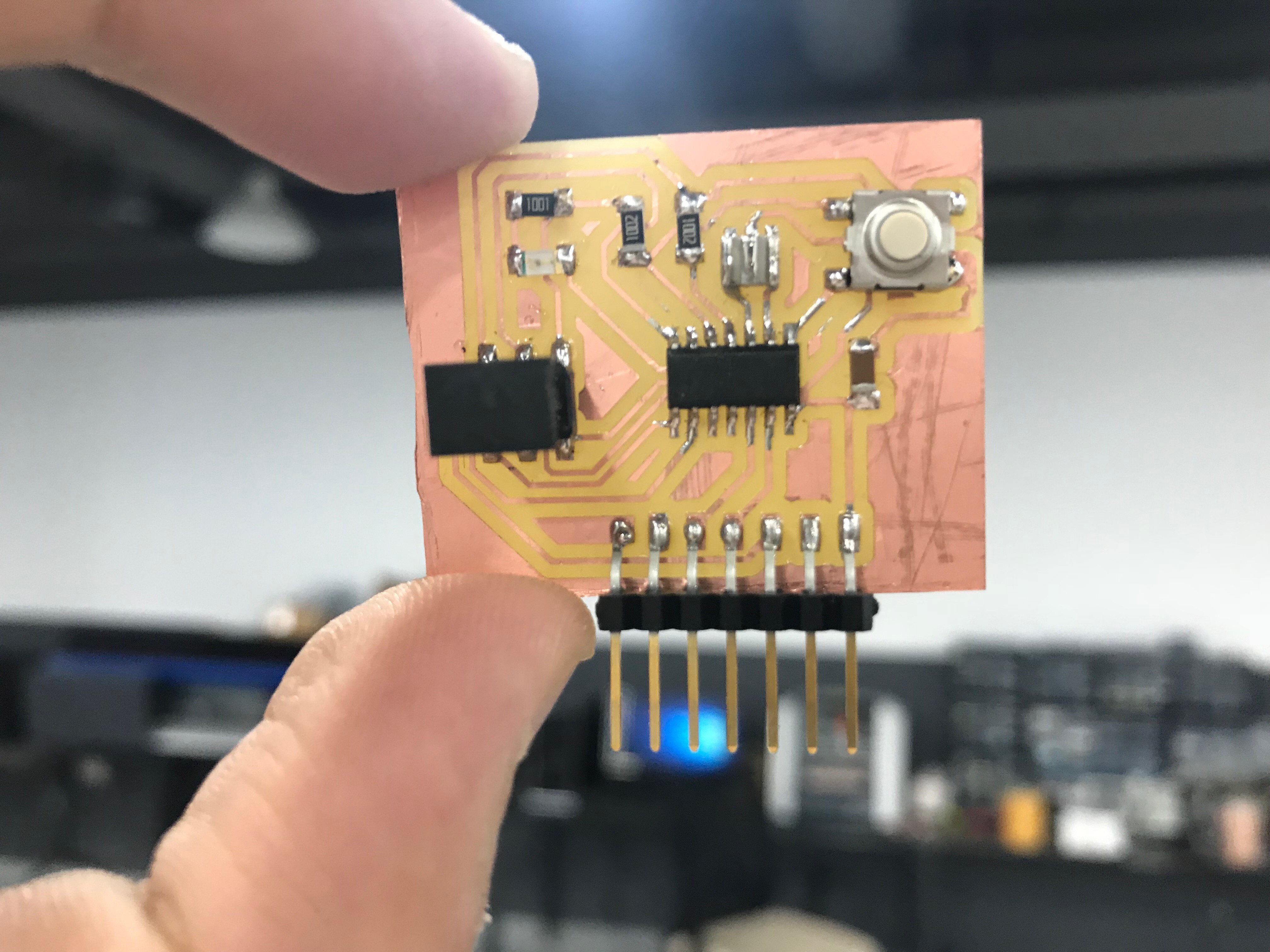
Testing the board
In order to check if the board was working, we had to tested the serial commumication between my micro-controller and my laptop(Arduino). I donwloaded the c file and the make file (ADD LINK) then I ran `make program-usbtiny` via the terminal and then I ran `make program-usbtiny-fuse`. My board wasnt sending the text back, thus I had to inspect my board using multimeter, the crystal clock wasnt soldered propeprly. I re-soldered it, my board started sendng the text back. Group Assignment
During the group assignment we have tested the serial communicvation of the micro-controller and the switch de-bounce effect
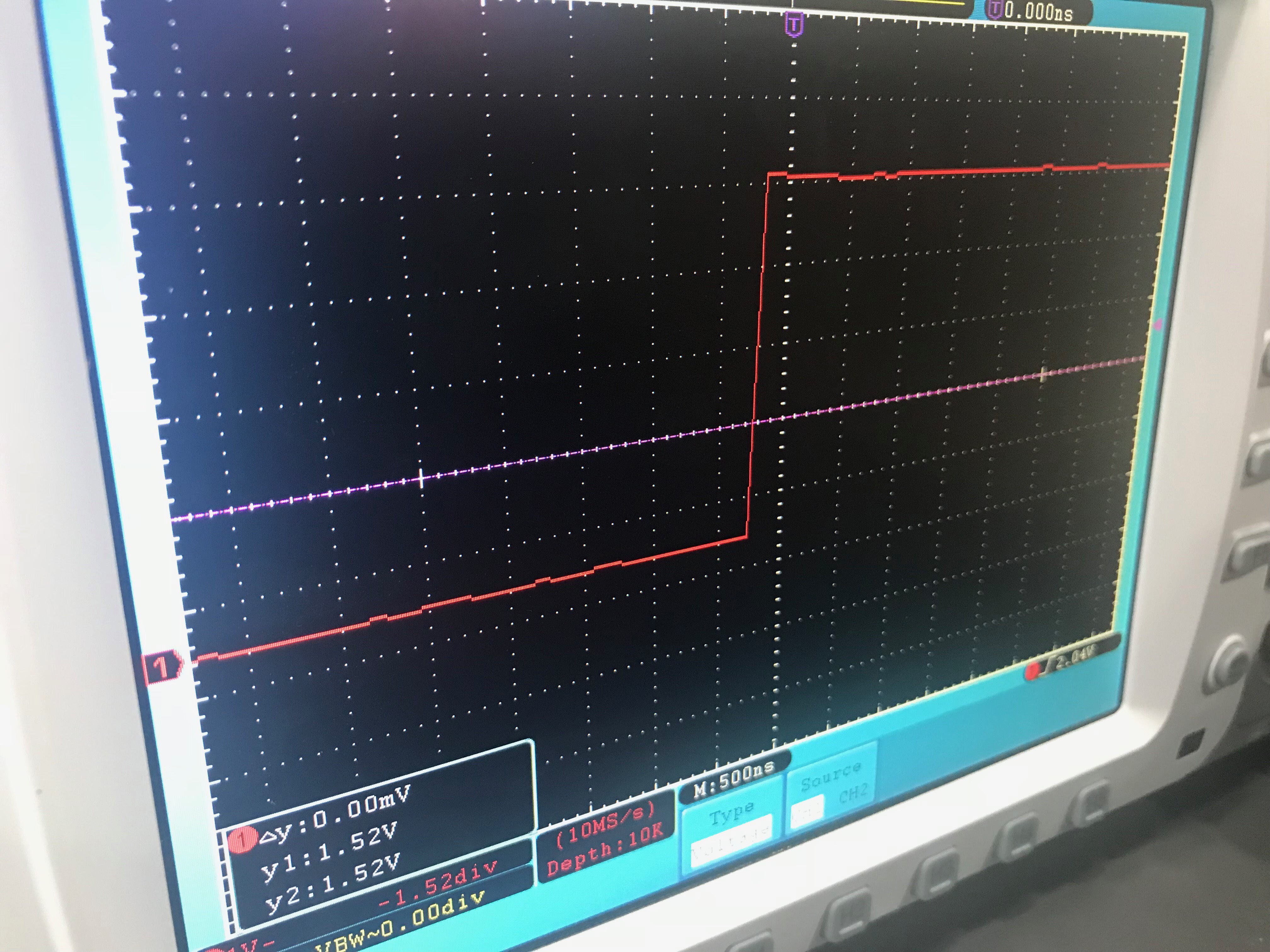
.jpeg)
