Embedded programming
This week task is to create a program to our fabricated board which contains an LED and a Button. At the begging I am going to use Arduino and c programming to blink the LED once the button is pressed, then I ll try to turn the LED on only if you press the button three in a row. For c programming I will try using interrupts to increase the efficiency of the chip.
Arduino
The Aatiny family wont be available on arduino IDE, to add it copy the link available at this link and paste in the Arduino IDE prefrence. From tools just access board manager and install Aatiny core.
** Make sure to select Aatiny 44**
Blink LED once button is pressed taking into consideration only the rising edge
//LED button code, turns on the led once the button is pressed
// Murad Saadeh
// 17/3/2017


int led = 7; // as PA7 is represented as 7 in arduino
int button = 8; // as PB2 is represented as 7 in arduino
int buttonlocation = 0;
int y = 0;
int previous = 0;
// the setup routine runs once when you press reset:
void setup() {
  // initialize the digital pin as an output.
  pinMode(led, OUTPUT);
pinMode(button, INPUT);

}

// the loop routine runs over and over again forever:
void loop() {
  previous = buttonlocation;
  buttonlocation = digitalRead (button);


      if (buttonlocation == 1 && previous == 0)

    {
      digitalWrite(led, HIGH);   // turn the LED on (HIGH is the voltage level)

     }
          if (buttonlocation == 0 && previous == 1)
    {
     digitalWrite(led, LOW);    // turn the LED off by making the voltage LOW

    }
}
Blink LED once the button is pressed 3 times taking into consideration only the rising edge
To perform that a counter that count each time you press must be added every time the button was off and then on ( as the de-bounce could affect this). Once the integer equals to three turn on the Led.
//LED button code, turns on the led once the button is toggeled
// Murad Saadeh
// 17/3/2017


int led = 7; // as PA7 is represented as 7 in arduino
int button = 8; // as PB2 is represented as 7 in arduino
int buttonlocation = 0;
int y = 0;
int previous = 0;
// the setup routine runs once when you press reset:
void setup() {
  // initialize the digital pin as an output.
  pinMode(led, OUTPUT);
pinMode(button, INPUT);

}

// the loop routine runs over and over again forever:
void loop() {
  previous = buttonlocation;
  buttonlocation = digitalRead (button);


      if (buttonlocation == 1 && previous == 0)

    {

      y = y +1;

     }
        if (y == 3){
           digitalWrite(led, !digitalRead(led));   // turn the LED on (HIGH is the voltage level)
           y = 0;
        }

}
Blick LED on and off when the button is pressed taking into consideration only the rising edge
//LED button code, turns on the led once the button is toggeled
// Murad Saadeh
// 17/3/2017


int led = 3; // as PA7 is represented as 7 in arduino
int button = 8; // as PB2 is represented as 7 in arduino
int buttonlocation = 0;
int y = 0;
int previous = 0;
// the setup routine runs once when you press reset:
void setup() {
  // initialize the digital pin as an output.
  pinMode(led, OUTPUT);
pinMode(button, INPUT_PULLUP);

}

// the loop routine runs over and over again forever:
void loop() {
  previous = buttonlocation;
  buttonlocation = digitalRead (button);


      if (buttonlocation == 1 && previous == 0)

    {

      y = y +1;

     }
        if (y == 3){
           digitalWrite(led, !digitalRead(led));   // turn the LED on (HIGH is the voltage level)
           y = 0;
        }

}
C-Programming
Blick LED once button is pressed
This code is very similar to the Arduino code, however when using c code at the beginning of the code clock speed must be defined, and also the include libraries. My led is connected to pin PA3 while my button is connected to pin PB2. As I have not added a pull up or pull down resistor, I must activate the internal pull up resistor, this is done by setting the input port B to 1.
// Murad Saadeh
// 17/3/2018
// This program flashes the LED when the button is toggeled


#define F_CPU 1000000UL // clock 20MHZ external
#include <avr/io.h>
#include <util/delay.h> // include the delay library

int main (void)
{
DDRA = 0b00001000; //set PA3 as output(LED)
DDRB = 0b00000000; //set PB2 as input (button)
PORTB = 0b00000100; //activate pull up register


while(1) {
        if (PINB == 0b00000100) // read input pin
        {
          PORTA = 0b00000000; // turn LED on
          }
          else {
            PORTA = 0b00001000; // turn LED off
          }
}
}
          }
}
}
Blink LED once button is pressed using bed-shifting
Bed shifting is a very useful and efficient way to write c code, bed shifting means to shift a register either left or right by specific number. For example to shift 01010001 by 3 to the left = 10001000 without carry and 10001010 with carry.
// Murad Saadeh
// 19/3/2018
// This program flashes the LED when the button is toggeled using bed shifting


#define F_CPU 1000000UL // clock 20MHZ external
#define setbit(register, bit) (register) |= (1 << (bit))
#define clearbit(register, bit) (register) &= ~(1 << (bit))
#define testbit(register, bit) (register) & (1 << (bit))
#include <avr/io.h>
#include <util/delay.h> // include the delay library

int main (void)
{
setbit (DDRA, PA3); //set PA3 as output(LED)
clearbit (DDRB, PB2); //set PB2 as input (button)
setbit (PORTB, PB2); //activate pull up register


while(1) {
        if (!testbit (PINB, PB2)) // read input pin
        {

		PORTA ^= (1 << (PA3));  //toggle the led
          }

}
}
Blink LED once button is pressed using internal interrupts
Using interrupts is more efficient way to interrupt a code and perform a specific task. First of all you must choose which port are you interrupting then choose which pin is going to change so the program interrupt (check comments available at the code below for more info). Moreover make sure to add the interrupt library and the global interrupt ( I-bit). setting the global interrupt (I-bit) is done by sei();
// Murad Saadeh
// 19/3/2018
// This program flashes the LED when the button is toggeled using interrupts


#define F_CPU 1000000UL // clock 20MHZ external
#define setbit(register, bit) (register) |= (1 << (bit))
#define clearbit(register, bit) (register) &= ~(1 << (bit))
#define testbit(register, bit) (register) & (1 << (bit))
#include <avr/io.h>
#include <util/delay.h> // include the delay library

int main (void)
{
setbit (DDRA, PA3); //set PA3 as output(LED)
clearbit (DDRB, PB2); //set PB2 as input (button)
setbit (PORTB, PB2); //activate pull up register


GIMSK |= (1 << (PCIE1)); // enabale interrupt in port b
PCMSK1 |= (1 << (PCINT10)); // interrupt in pb2

sei(); //activating global interrupt

while(1)
}

ISR (PCINT1_vect1)
{
(PORTA) ^ (1 << (PA3));    // turn LED on
}
Blink LED once button is pressed using external interrupts INT0 and interrupting on rising edge only
This is very similar to the internal interrupt however, the only benefit is that the external interrupt code interrupt on rising edge or falling edge or both which makes more useful than internal interrupts. The procedure is very similar to internal interrupts but as the external interrupt is only availabe at PB2 in Aatiny 44 so they will be need to define which pin we are using. make sure to select if you are interrupting on rising or on falling edge or both, moreover make sure to change the interrupt vector to the external interrupt.
// Murad Saadeh
// 20/3/2018
// This program flashes the LED when the button is pressed using external interrupts


#define F_CPU 1000000UL // clock 20MHZ external
#define setbit(register, bit) (register) |= (1 << (bit))
#define clearbit(register, bit) (register) &= ~(1 << (bit))
#define testbit(register, bit) (register) & (1 << (bit))
#include <avr/io.h>
#include <util/delay.h> // include the delay library
#include <avr/interrupt.h> // include interrupt library

int main (void)
{
setbit (DDRA, PA3); //set PA3 as output(LED)
clearbit (DDRB, PB2); //set PB2 as input (button)
setbit (PORTB, PB2); //activate pull up register


GIMSK |= (1 << INT0); // enabale external interrupt in port b
MCUCR |= ((1 << ISC00) | (1 << ISC01)); // enable interrupt on risings edge


sei(); //activating global interrupt

while(1) {}
}

ISR(INT0_vect)
{
PORTA ^= (1 << PA3);    // turn LED on
}
Blink LED once button is pressed using internal interrupts on rising edge only
This code is way to interrupt rising edge using internal interrupts to do that you ll have to add an if statement inside the interrupt vector that its only true if the button is on a rising edge (HIGH).
// Murad Saadeh
// 19/3/2018
// This program flashes the LED when the button is toggeled using interrupts


#define F_CPU 1000000UL // clock 20MHZ external
#define setbit(register, bit) (register) |= (1 << (bit))
#define clearbit(register, bit) (register) &= ~(1 << (bit))
#define testbit(register, bit) (register) & (1 << (bit))
#include <avr/io.h>
#include <util/delay.h> // include the delay library
#include <avr/interrupt.h> // include interrupt library

int main (void)
{
setbit (DDRA, PA3); //set PA3 as output(LED)
clearbit (DDRB, PB2); //set PB2 as input (button)
setbit (PORTB, PB2); //activate pull up register


GIMSK |= (1 << (PCIE1)); // enabale interrupt in port b
PCMSK1 |= (1 << (PCINT10)); // interrupt in pb2

sei(); //activating global interrupt

while(1) {}
}

ISR(PCINT1_vect)
{
  if (PINB == 0b00000100){
PORTA ^= (1 << PA3);    // turn LED on
}
}
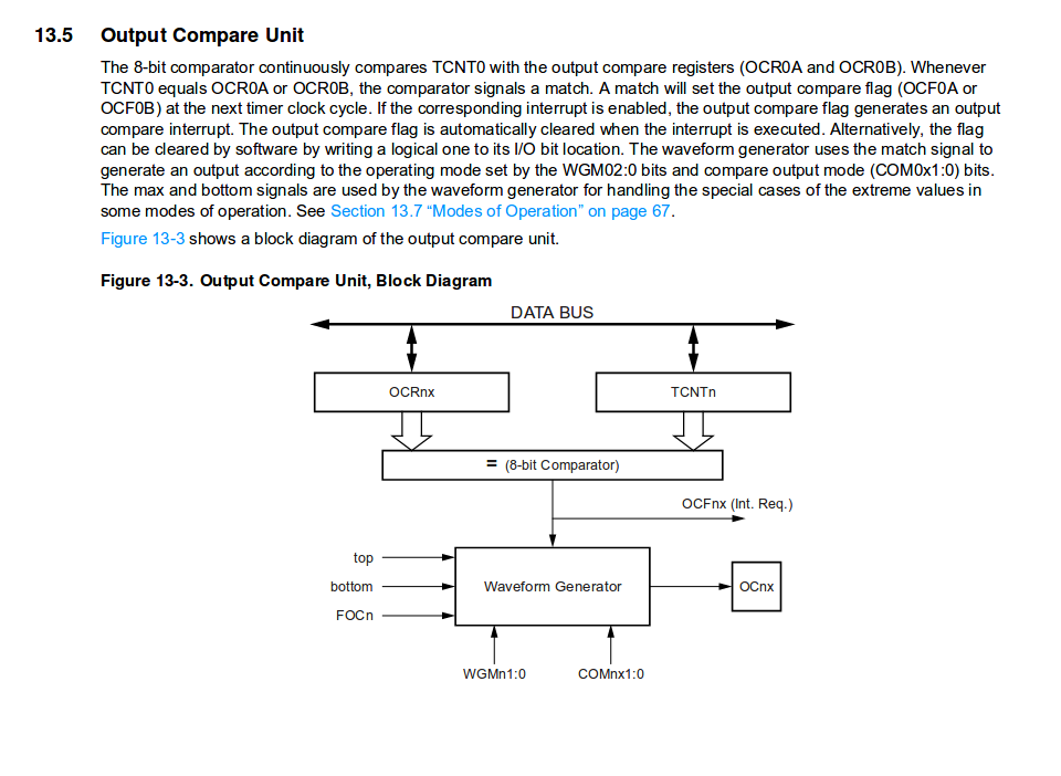
Increase the brightness of the LED using Pulse Width modulation
Pulse Width Modulation: is a technique used to generate analog output signal using digital signals. The duty cycle is usually 100% and depend on which timer you use this 100% could be represented by either 8bit timer or the 16 bit timer. The most simpliest way to use PWM is fast pwm. similar to timer, setting pre-scaler start the PWM.
// Murad Saadeh
// 19/3/2018
// This program flashes the LED using Pulse width modulation
#define F_CPU 1000000UL // clock 20MHZ external
#define setbit(register, bit) (register) |= (1 << (bit))
#define clearbit(register, bit) (register) &= ~(1 << (bit))
#define testbit(register, bit) (register) & (1 << (bit))
#include <avr/io.h>
#include <util/delay.h> // include the delay library
#include <avr/interrupt.h> // include interrupt library
int dutyCycle = 50;
int main (void)
{
setbit (DDRA, PA7); //set PA7 as output(LED)
clearbit (DDRB, PB2); //set PB2 as input (button)
setbit (PORTB, PB2); //activate pull up register
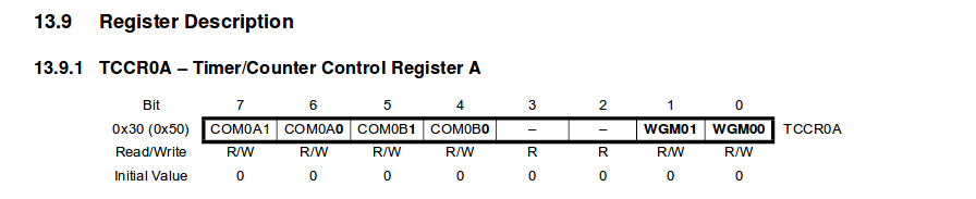
TCCR0A |= (1 << COM0B1); //Activate the clear on compare for OCOB mode
TCCR0A |= (1 << WGM00) ; //Activate the fast pwm
TCCR0A |= (1 << WGM01) ;// activate fast pwm
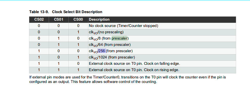
TCCR0B |= (1 << CS00) ;// use pre-scaler 1
//sei(); //activating global interrupt
while(1) {
dutyCycle+=10; // dutyCycle = dutyCycle + 10;
if (dutyCycle >250)
dutyCycle = 0;
OCR0B = dutyCycle;
_delay_ms(200);
}
}
Aatiny 44 data sheet
Interrupt on pin change
Interrupts is a better method than polling as the interrupt occurs immediately even if the program is in the middle of doing something else.
- Each pin has an internal interrupt labeled as PCINTx
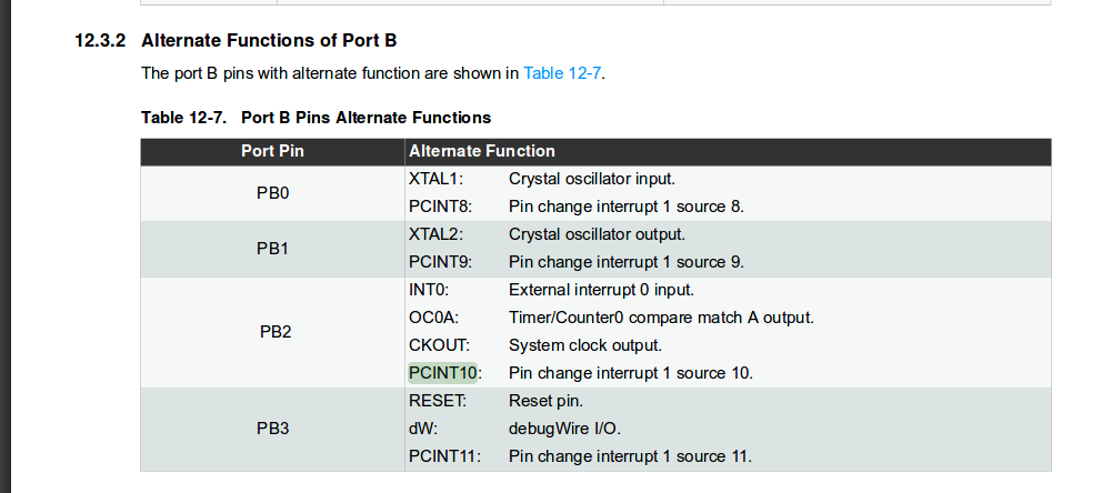
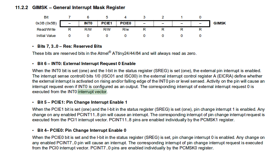
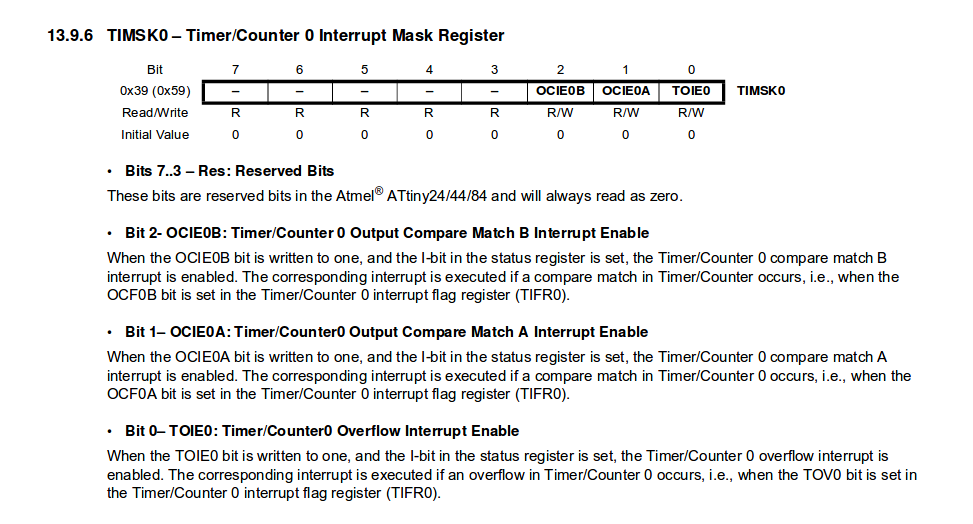
- Enable the interrupt in port A or B by setting GIMSK pins where PCIE1= port b and PCIE0 for port A
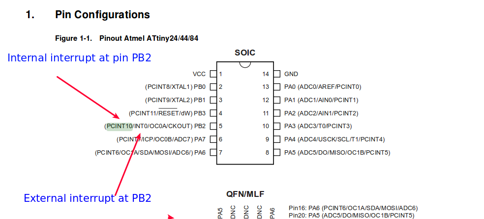
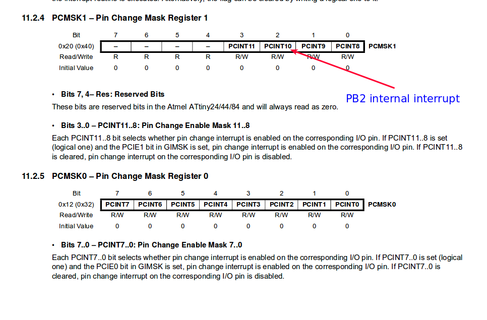
- Choose the pin you need to interrupt in my case PCINT10 = PB2
- Activate the global interrupt by
sei(); - Add the interrupt vector ISR statement which is PCINT1 for port b
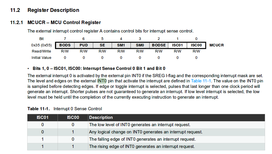
Interrupts on external pin (rising or falling edge)
This is very similar to the normal internal interrupt, however the only advanteges is that interrupting either on rising or falling edge can be achieved using the external interrupts
- The procedure is very similar to the internal interrupt but to define either rising edge or falling edge MCUCR register must be defined
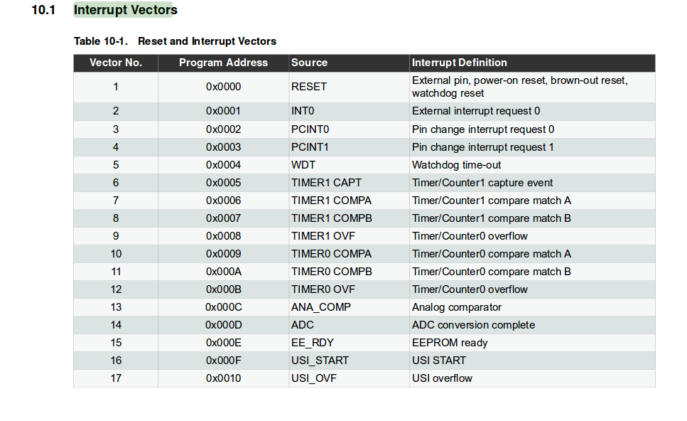
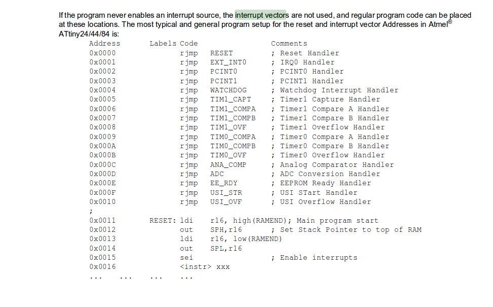
Interrupt vectors priority statement
The below schedule define which interrupt occurs first
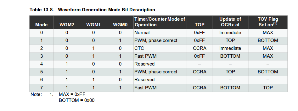
Timer
Timers would support user to translate clock frequency time to real time (seconds)
-
Enable clear to compare mode (CTC) by setting TCCR1B and TTCR1A (16 bit timer) and TCCR0B and TTCR0A (8bit timer)
-
Set the interrupt mask register (TIMSK0 8 bit) or (TIMSK1 16 bit) to either compare on math b or a.
-
set the bits ( 15625 bit = 1 sec at pre-scaler 64 using 16 bit timer) desired at OCIE1A
-
set the pre-scaler


interrupt vectors priority statement
The below schedule define which interrupt occurs first
Problem faced
interrupt vectors priority statement
The below schedule define which interrupt occurs first
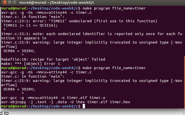
- I added the number 39204 to OCR0A which is the 8 bit register ( maximum 255 bits ), I changed it to the OCR1A 16 bit timer and it worked perfectly.