Computer controlled machining
2D design principles:
I am kind of new to the whole designing concept, I have previously used solid works to create and laser cut press fit construction kit and I have used on-shape to design my 3d coffee pot. For this week I will be using Fusion 360, as I have read a lot of good reviews on how good it is specially when creating furniture and working with the shop-bot. I have face some problem at the begging of the design as I had difficulties processing the 2d design object in my head. I have seen some youtube video where they create the 3d object first then use the sketches to design it ( link available below the source files ). My initial idea was to create a recycling bin, which is press fit attached and fully parametric. I have learn a lot from this experience, however unfortunately I didn’t end up doing it.
- In order to design a 3d model for your furniture always try to place the first piece on the origin, this would extremely ease up the rest of your design as you could easily just refer to the origin when adding more objects.
-
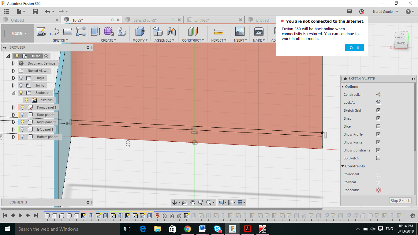
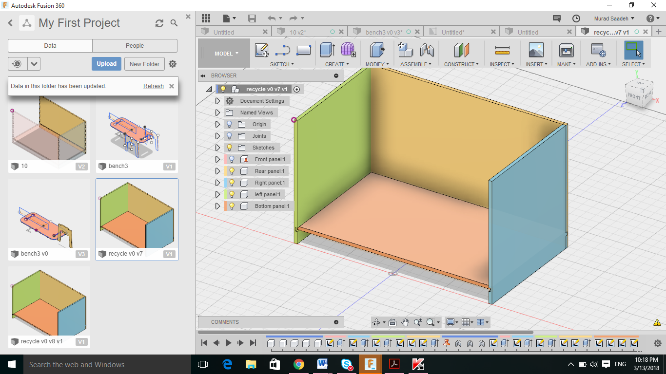
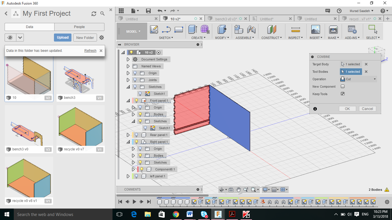
Always do constrain your drawing either with constrains or with other line or point, this will make your entire design parametric. In my case when I draw the first triangle (front panel) I have constrained it with the mid origin point. Moreover when I designed the right panel for example the height of the right panel designed with constrains to the front panel height. To do that when drawing the right panel just choose the 2 points from the front panel, thus if we changed the height of the front panel , the height of the right panel will change. In addition to that both panels will be attached to each other
-
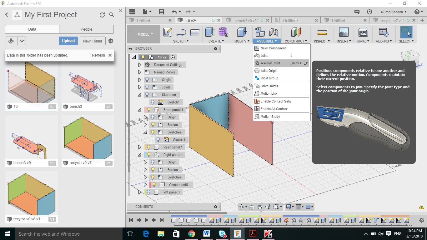
As built joint, the panel look attached however every panel is free to move around, thus by using as built joint tool you can actually attach the panel so they are not free to move around.
-
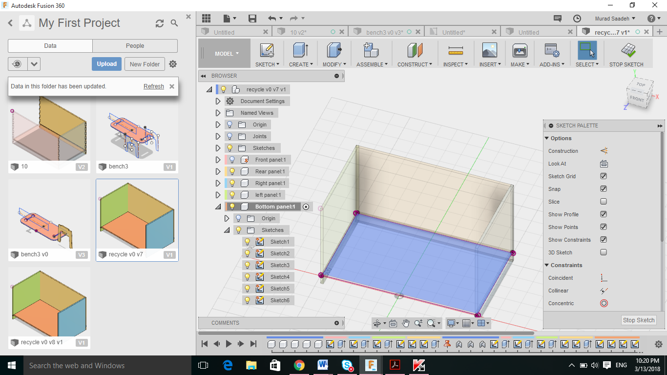
For the bottom panel, I need a strong panel to hold in all the weight of the garbage bag, thus I have decided to create some kind of a large rack ( large slot that goes around the entire panels) which will help to create the actual bottom panel. Once I have created the slot and extruded it for 10 mm inside, I then choose the inside slot area (line) and extruded it 17 mm. This had created the bottom panel press fit to the slots.
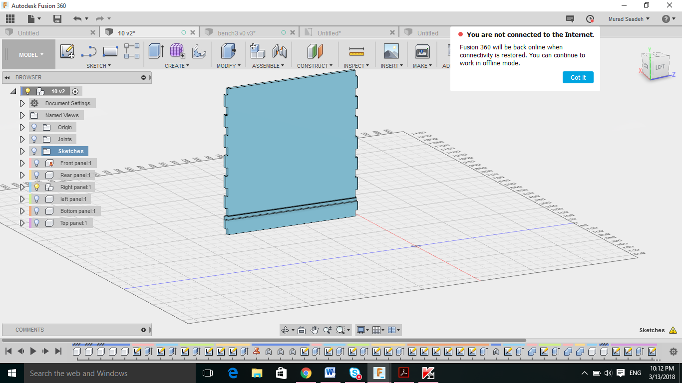
- To create the teeth and slot, I have drawn a teeth outside and manually made the 2 sides equal and then constrained the middle top side with mid point construction line, then I have constrained the construction line with the mid of the front panel, this had moved my teeth to the middle of the front panel, I have then used rectangular pattern to create the rest of the teeth, make sure to choose symmetric to have them correctly spread on both sides.
Problem faced with designing the recycling bin
I have decided to go through with designing a bench and then if I have time, I will design a complicated design to challenge myself. I faced some complication designing the garbage bin as how to actually design a mechanism that would ease lifting and replacing the garbage bags. I wanted to create some kind of a hinge on the top panel and remove the bag from the top, and have some sort of a lock mechanism to lock the panels if the top panel is there.
Bench design
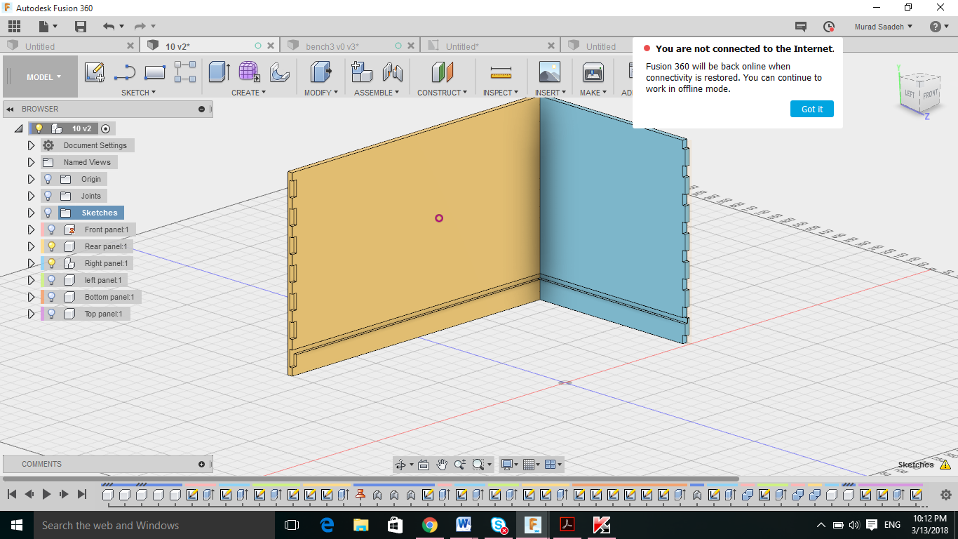
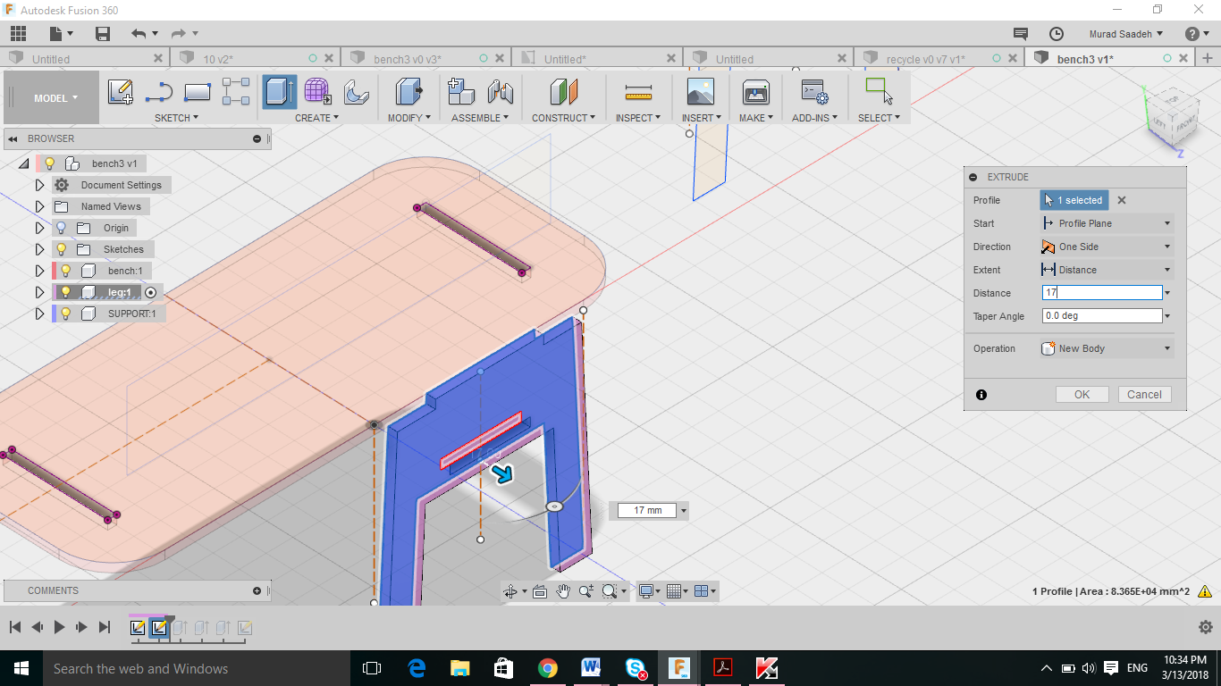
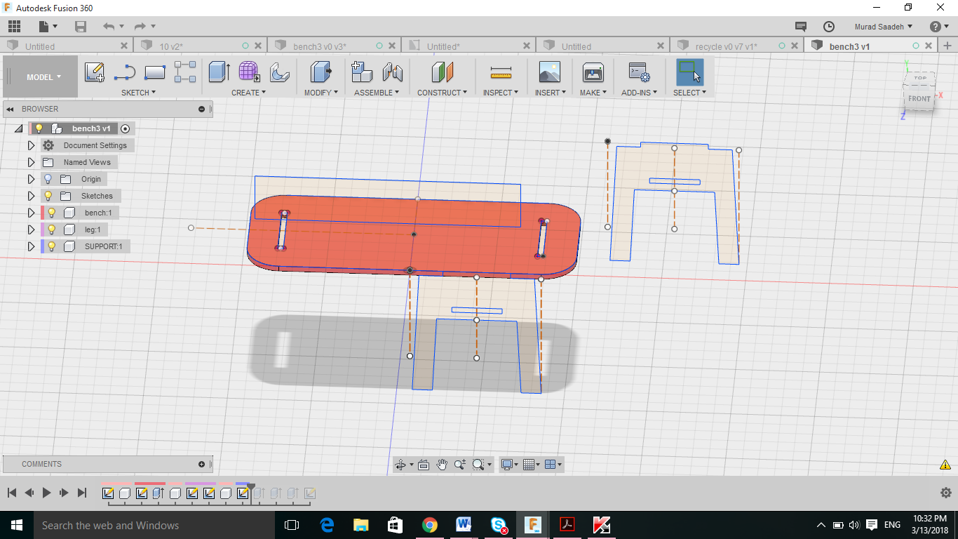
To design the bench I have created the seat area then designed two legs that could press fit to the bench and between those 2 legs, I ll have a support that stabilize my design.
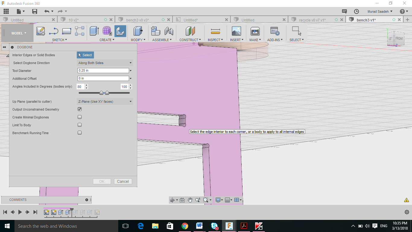
- To add dog-bone/ T-bone using fusion, Download the zip file from this link and then from fusion access the add on and choose the dog bone file that you extracted. The dog bone feature will be added to your main interface window. However I have encountered some difficulties creating dog-bone on sketch, as it will only work on 3d model object so I had to extrude my design and then add the dog bone. Dog bones couldn’t be created for the bench itself, I tried different technique thus I have created them using v-carve.
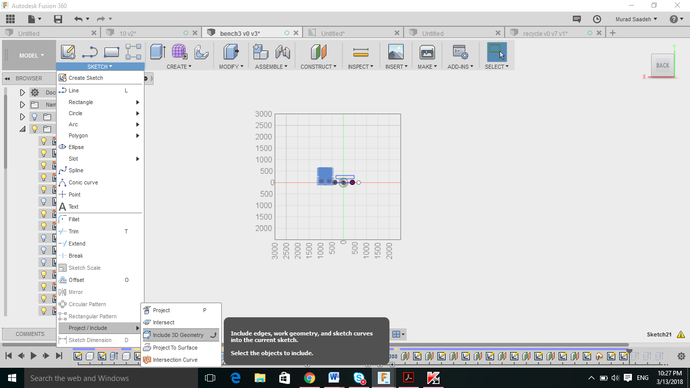
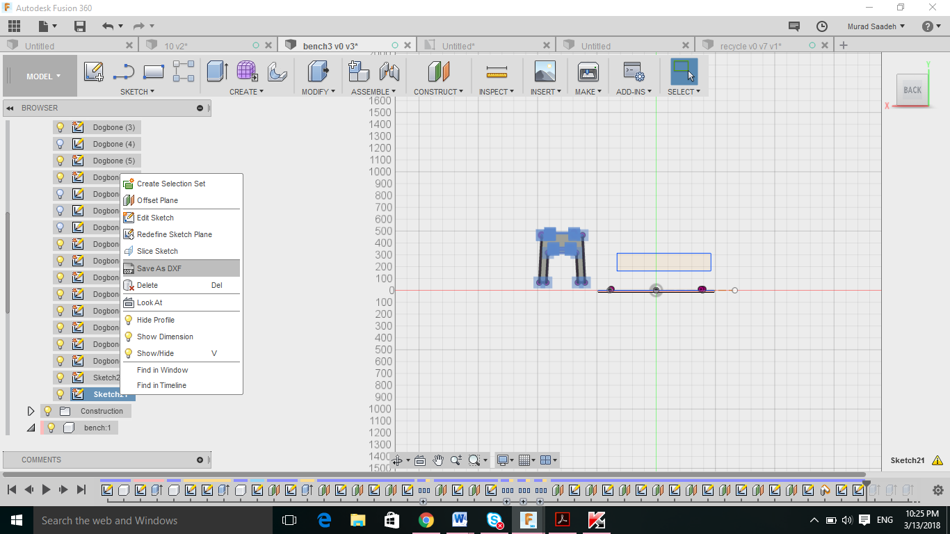
- Exporting dxf sketches with the dog bone, when trying to export sketches it would only export the sketch without the dog bone, thus to do that you must create a sketch and then include 3d geometry and manually select the lines and create the sketch and save it as dxf.
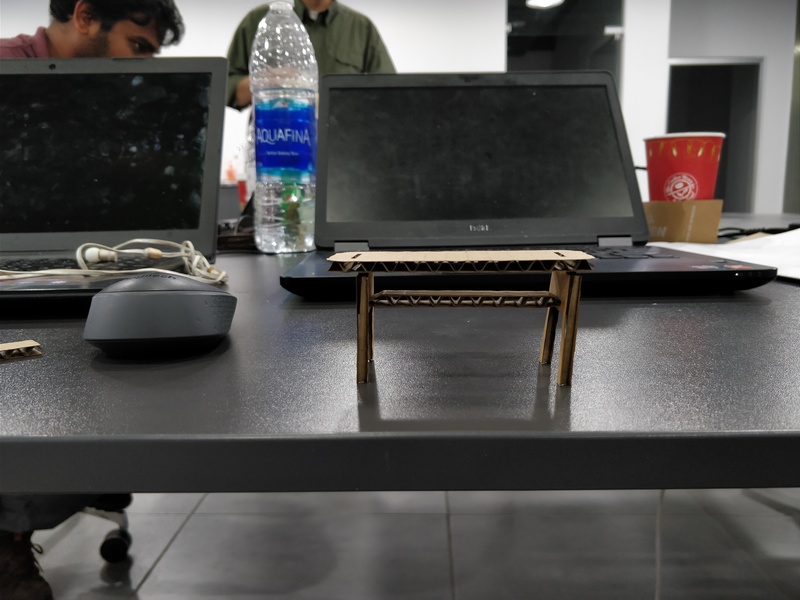
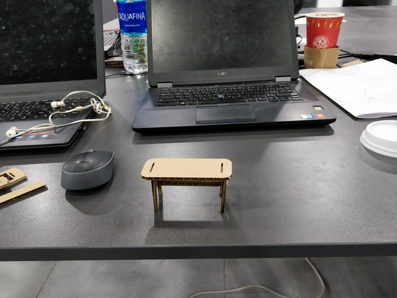
Final design
Source files
Recycling bin fusion file
click to downloadbench fusion file
click to downloadrefrence youtube video
Youtube linkTest my design
In order to test my design and make sure all the parameter are fir perfectly, I have exported the dxf file and used inskcape and then laser cut my object.
 Problem faced:
- The construction line from fusion are shown in the dxf file. I have to manually delete them using inkscape
- When exporting my dxf file, it had automatically created more than one line in the same position.
Shop-bot
Our instructor Sibu has explained some working and cutting techniques regarding the shop bot:
- Feed rate: how fast the bit moves across the wood sheet, cant go very fast as cooling is needed to not set the wood on fire. it usually ranges from 1-3 inch per second
- Down cut milling tool: Those are usually used to create a soft upper layer, its mainly used to only cut the first 5-7 mm on the plywood and then for a better finish to replace it with a upper cut. For down cut the speed rate must be low and the depth cut should also be decreased.
- Up-cut milling tool: This bit is usually used to create a smooth surface at the end of the wood.
- Climb milling: The bit rotate clock wise, so for climb milling the bit moves with the direction of its rotation
- Conventional milling: Milling bit moves in the opposite direction of rotation ( bit rotate clock wise and moves backward).
- Dog-bone: As the cutting bit is rounded it would face some difficulties creating 90 degree angle, thus it better to create a dog bone which will create some kind of a rounded edge at one of the sides
- T-bone: its similar to the dog-bone but it create a rounded edge at both sides.
Problem faced:
- We have downloaded the gadgets library for V-carve to be able to add t-bone and dog bone to our design, the library requested a v-carve to be version 8.5, however after the update our v-carve was still 8.0. This caused it to be not that efficient as it would detect sometime and wouldn’t other times, thus it will make more sense to add them directly from fusion 360.
More information are available at our group assignment page Group assignment page
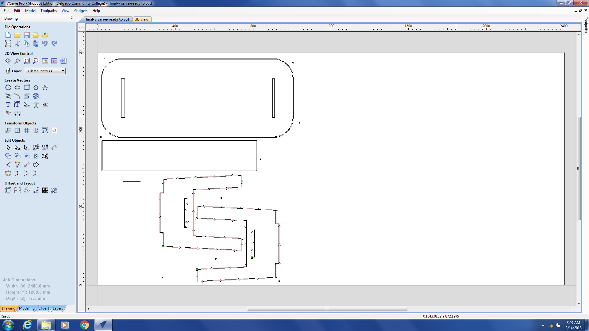
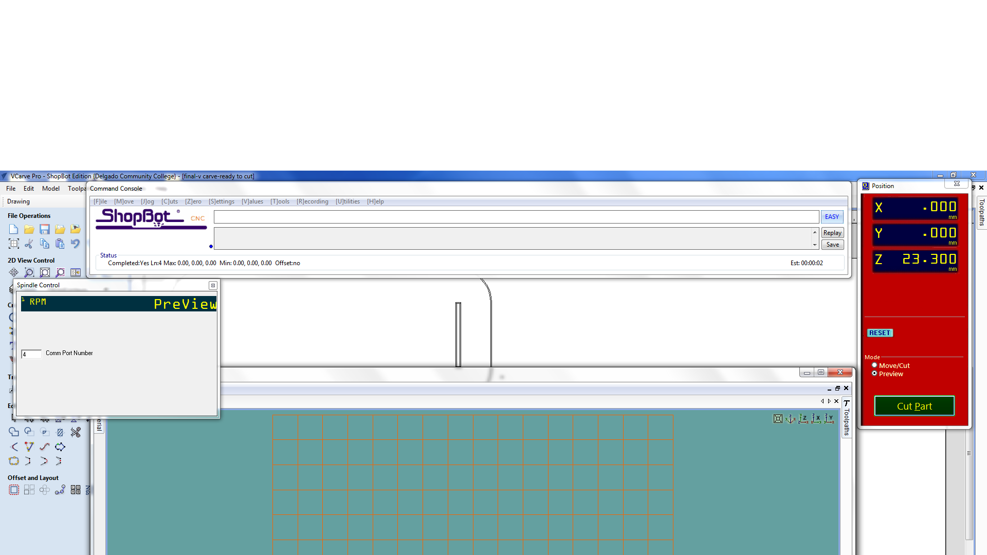
Cutting my design
- After exporting my dxf sketches from fusion, I have uploaded them to V-carve and selected the bed size 2400 width and 1200 length.
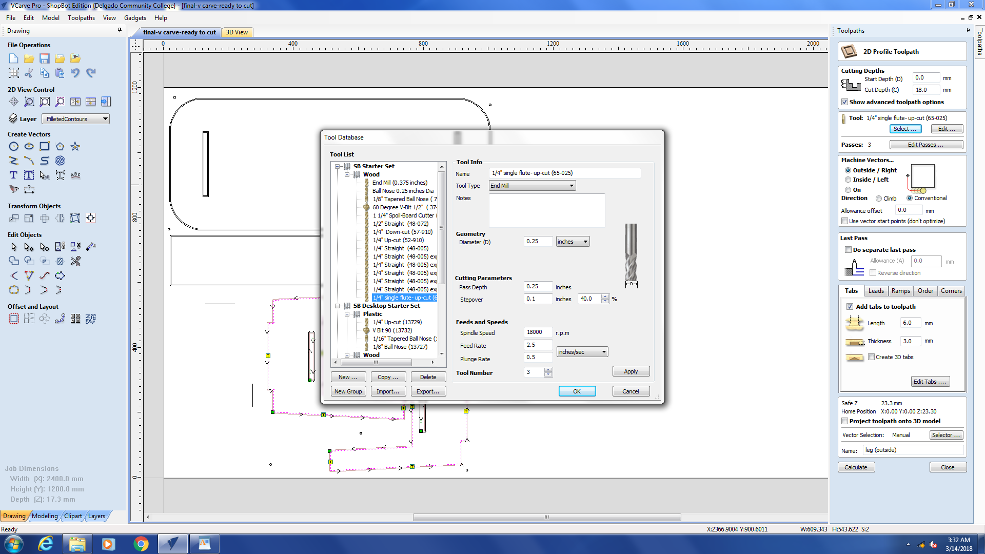
- I have changed the down-cut bit we used for the group assignment into a up cut bit ( Feed rate 2.5, Spindle =18000)
- I have zeroed the z-axis to the sacrificial wood ( Its much better as it wont cause any difference if our actual cutting wood is not evenly equal from every direction)
- I have used screws to hold on my cutting wood in place, to do that I have drawn circles with 6mm diameters.
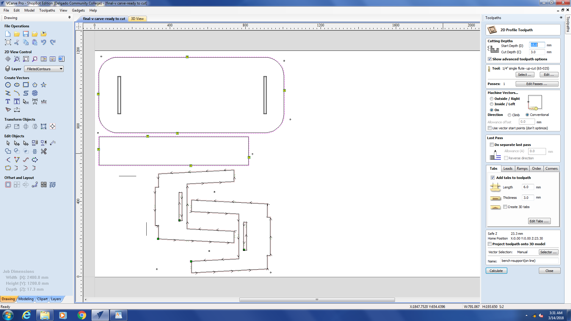
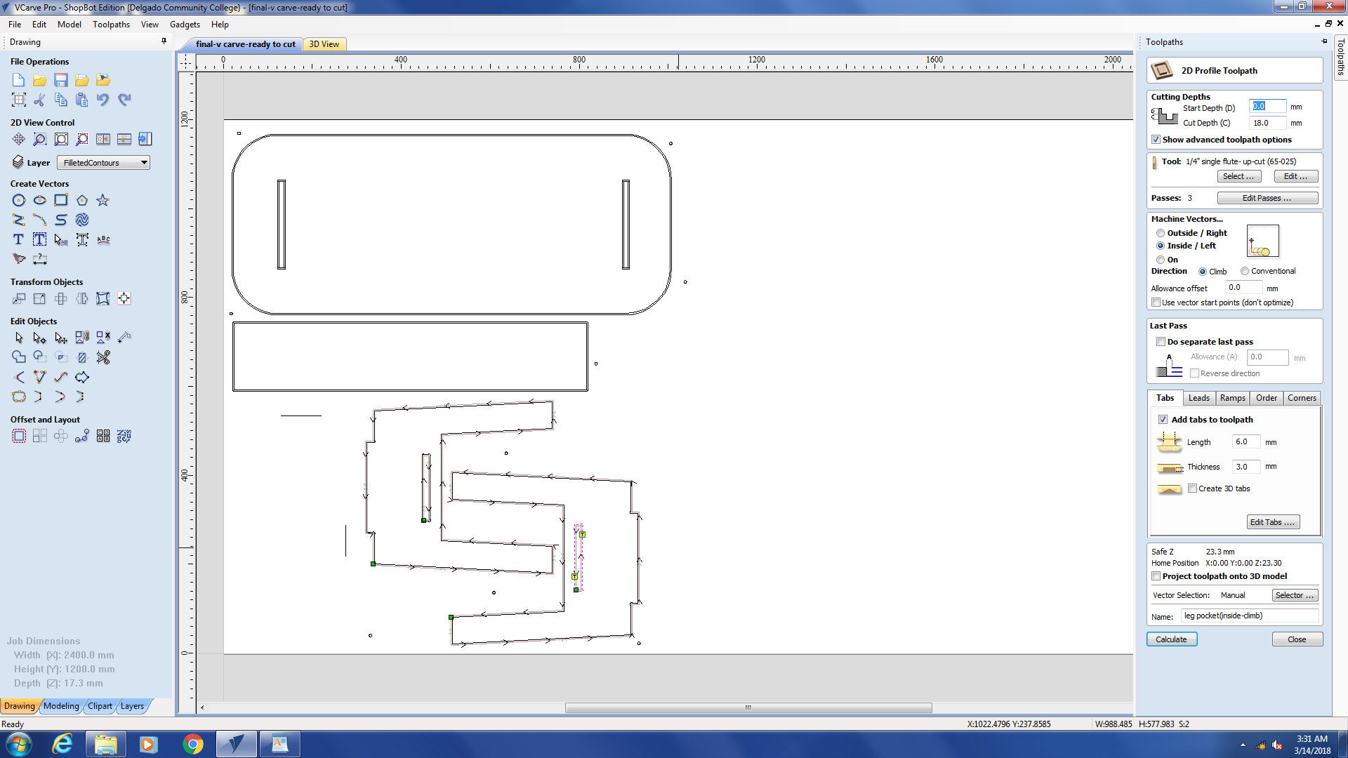
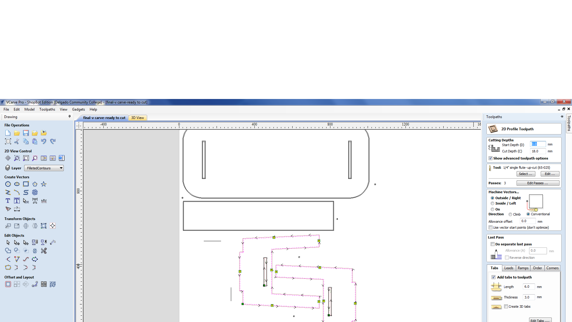
- I have then created profile tool path for all my sketches (17.4 cut depth, up cut milling bit, conventional).
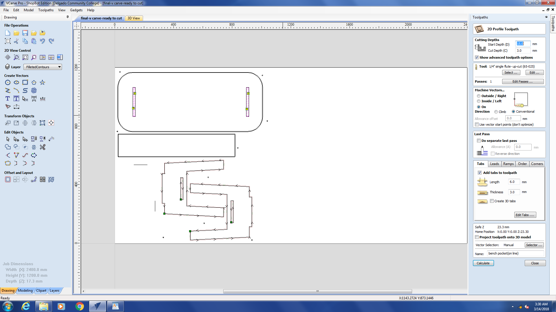
 Problem faced:
- The cut depth for my profiles where 17.4 where the thickness of the wood sheet is 17.3, this didnt actually cut all through so I have to amend my cut to start the cut at 15 mm ( as its already almost cut) and then cut down 3mm (cut depth ) which would be equivlent to me cutting 18 mm cut depth. This has worked fine for me.
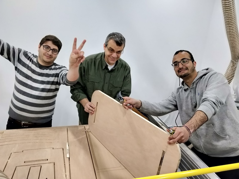
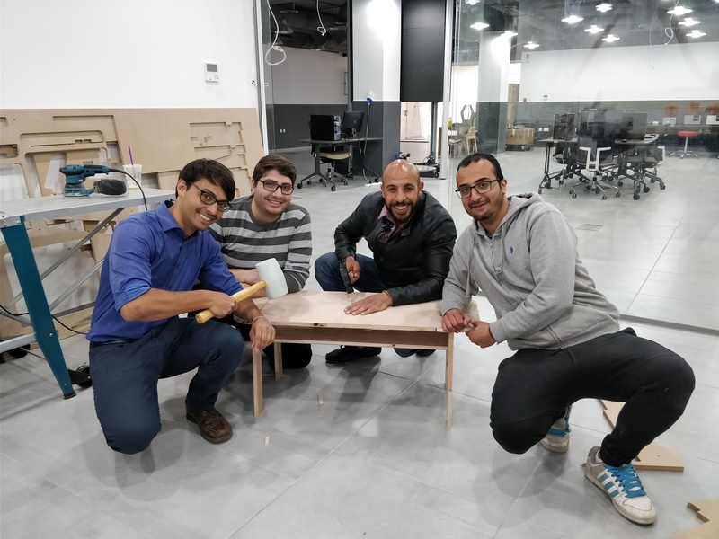
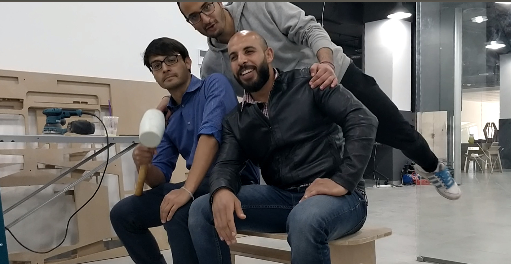
Assembling
The best was to assemble the bench is to first join the support with the 2 legs and then insert the 2 legs into the bench. the diameter of the pocket is 17 mm which was perfect to fit for the 17.33 mm wood without the need to use any screws. I had to rubber hammer the pieces a bit but it all went well. The wood we used wasn’t actually this good as pieces were easily broken specially side ways, but fortunately my bench is stable and was able to hold 2 of my friends sitting on it.
Milling bit review
Those 2 videos will help the user understand the differences between the milling bits, straight bit, up cut, and down cut
Youtube video linkYoutube video link