Computer aided design
I have very little experience in designing. I ll start today by learning on shape as its totally free and available to anyone, in
On shape:
Start a project:
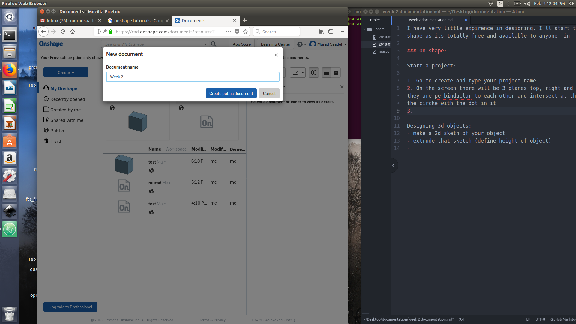
- Go to create and type your project name
- On the screen there will be 3 planes top, right and front plane [planes they are perpendicular to each other and intersect at the orgin which is the circle with the dot in it
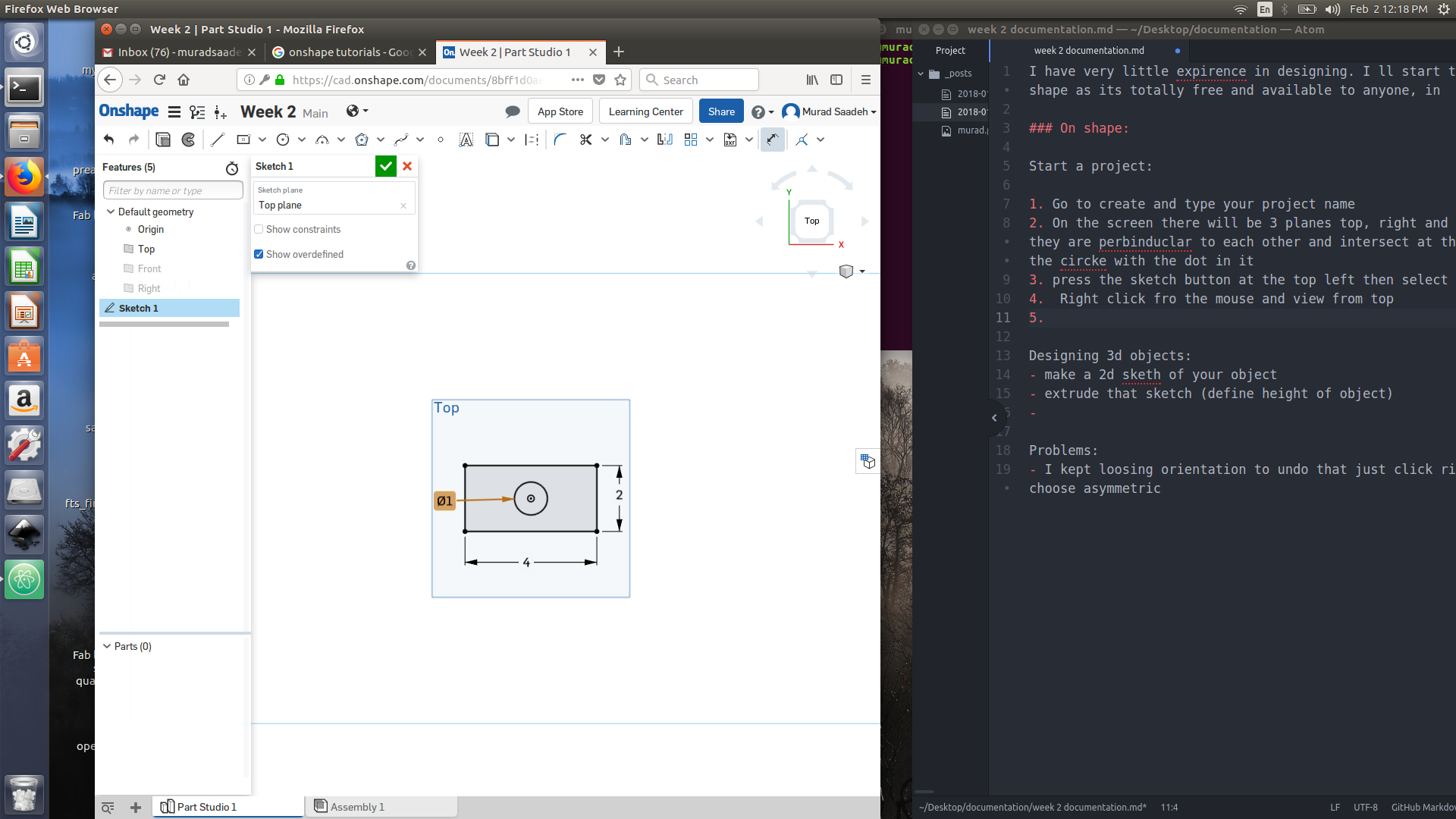
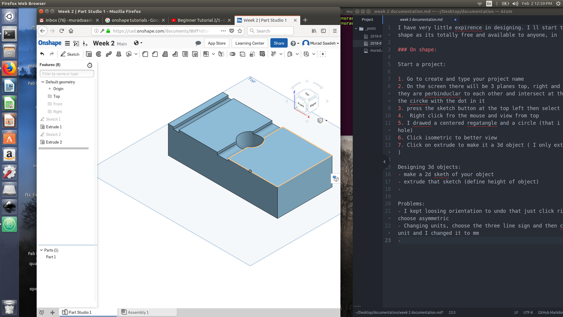
- press the sketch button at the top left then select the top `plane a
- Right click fro the mouse and view from top
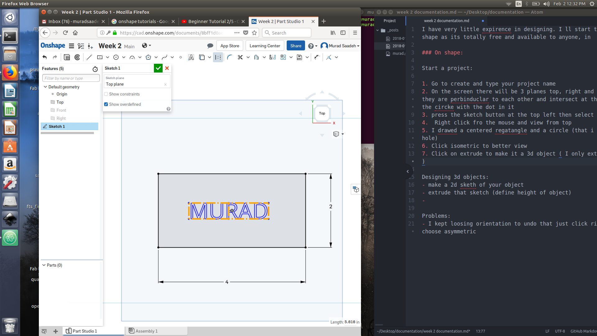
- I draw a centered rectangle and a circle (that i wanted to make as a hole)
- Click isometric to better view
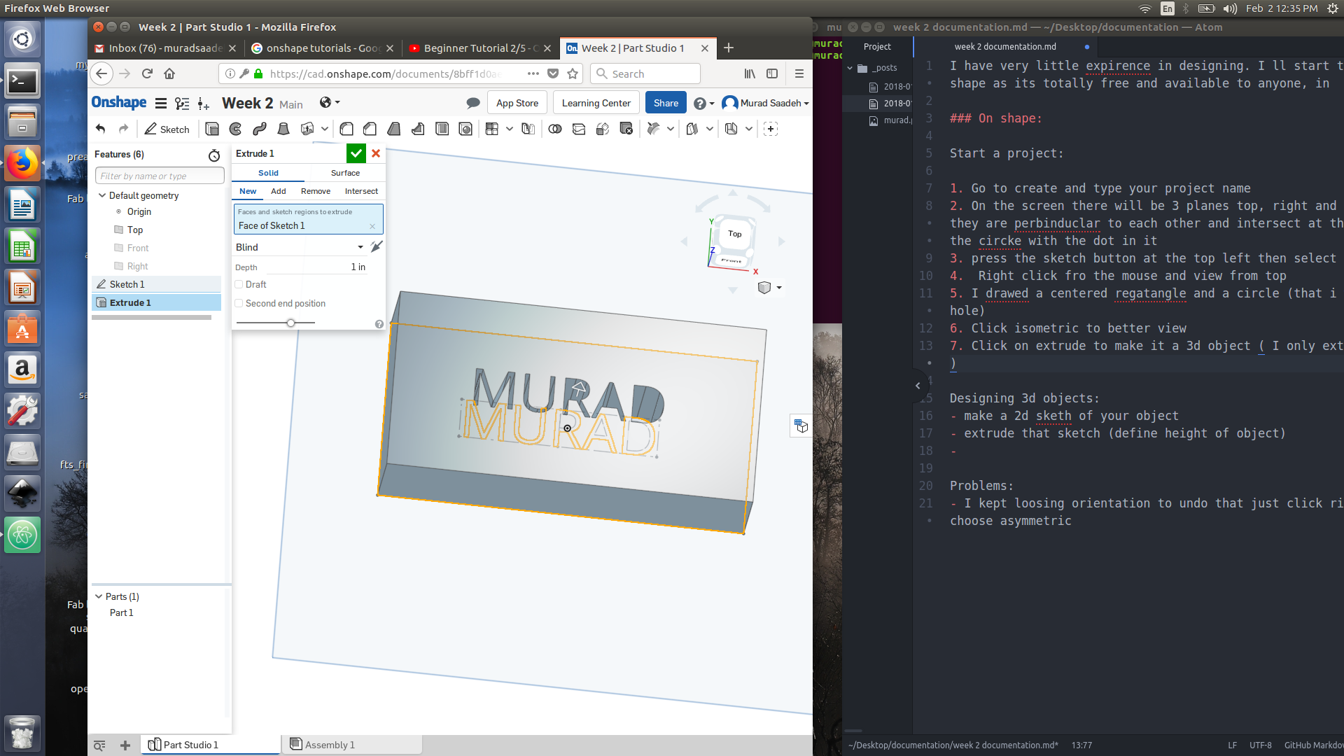
- Click on extrude to make it a 3d object ( I only extruded the rectangle )
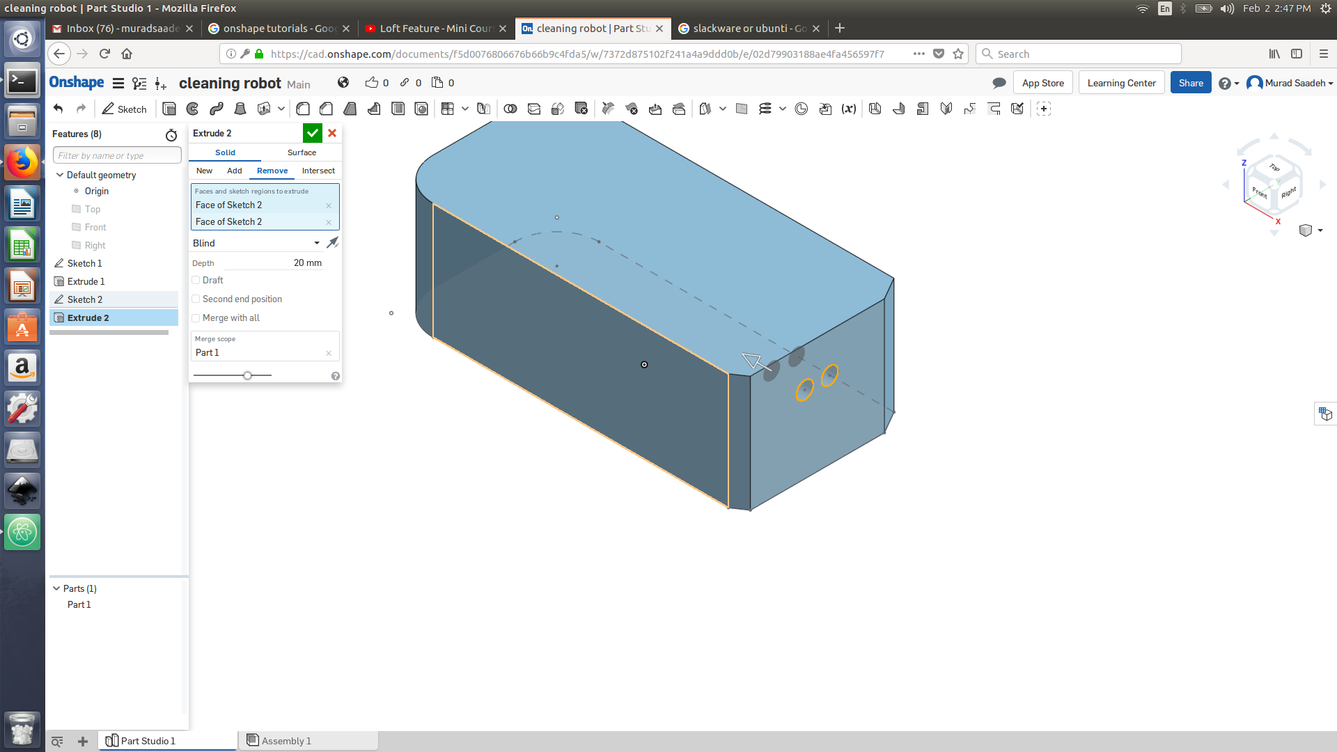
Designing 3d objects:
- make a 2d sketh of your object
-
extrude that sketch (define height of object)
Constraining objects:
- you can make a corner rectangle that would be contained to the edges of selected shapes
- If you choose dimension and choose the space between the rectangles lines, you will be able to constrain that as well.
- you can select 2 objects, or 2 lines and press on coincident and then press choose coincident again to constrain that
Mid point:
- To draw mid point line for a rectangle, choose construction line and then choose a line, move along the rectangle edges and you ll notice a a red square once you get to the center of the square then drag the construction line to the other end of the rectangle and press on it once the same red square center point appear.
Revolve command: is ideal for creating cylindrical and revolve against the axis
SWeep command: cross section or any closed contour and you want to write it on defined path make a sketch then make a sketch profile and sweep the path along the profile.
Loft command: create a smooth transition between two or more profiles for example between a circle and a triangle
Insert planes and sketch profile then sketch guide curves then create loft

Problems:
- I kept loosing orientation to undo that just click right click and choose asymmetric
-
Changing units, choose the three line sign and then click on workspace unit and I changed it to mm
On shape is a very powerful parametric tool to design 3d objects were you ll be able to set constrain to design with precision. All your data would be saved online and to access it and draw all what you need is a good Internet connection and a laptop
Xdesign by solid work:
I wanted to try using fusion 360 but its not compatible with linux thus I ll work on Xdesign software which is a cad software in the cloud
** I think Xdesign is not yet released as I have been trying to use from this like Link and the only opetion available is to sign up for coming news
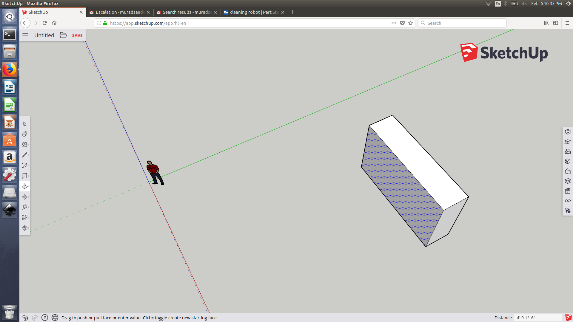
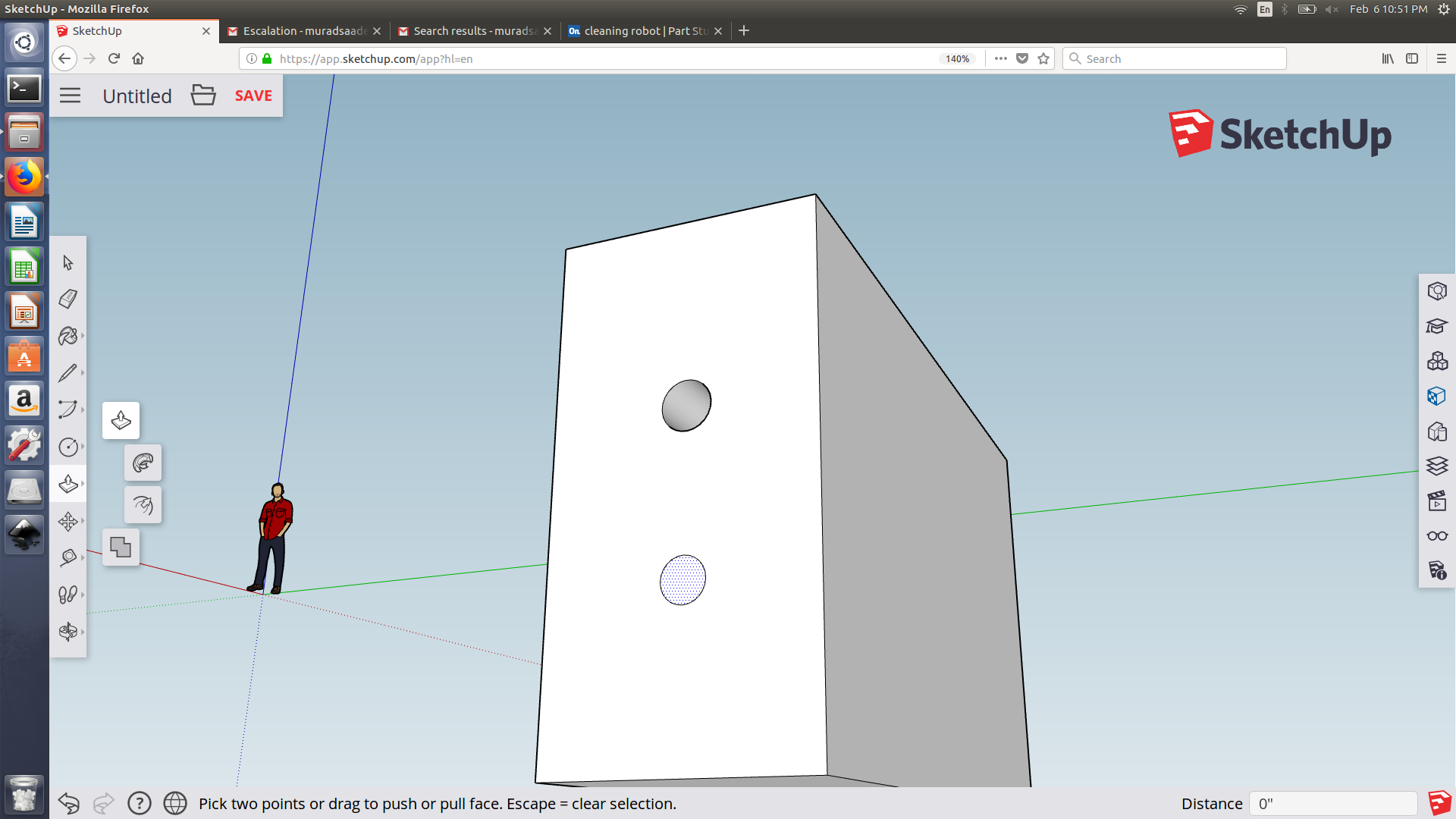
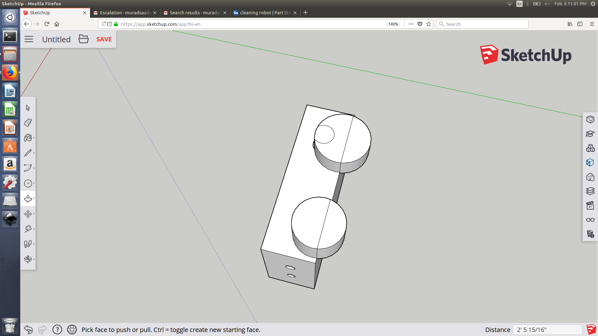
Sketch up
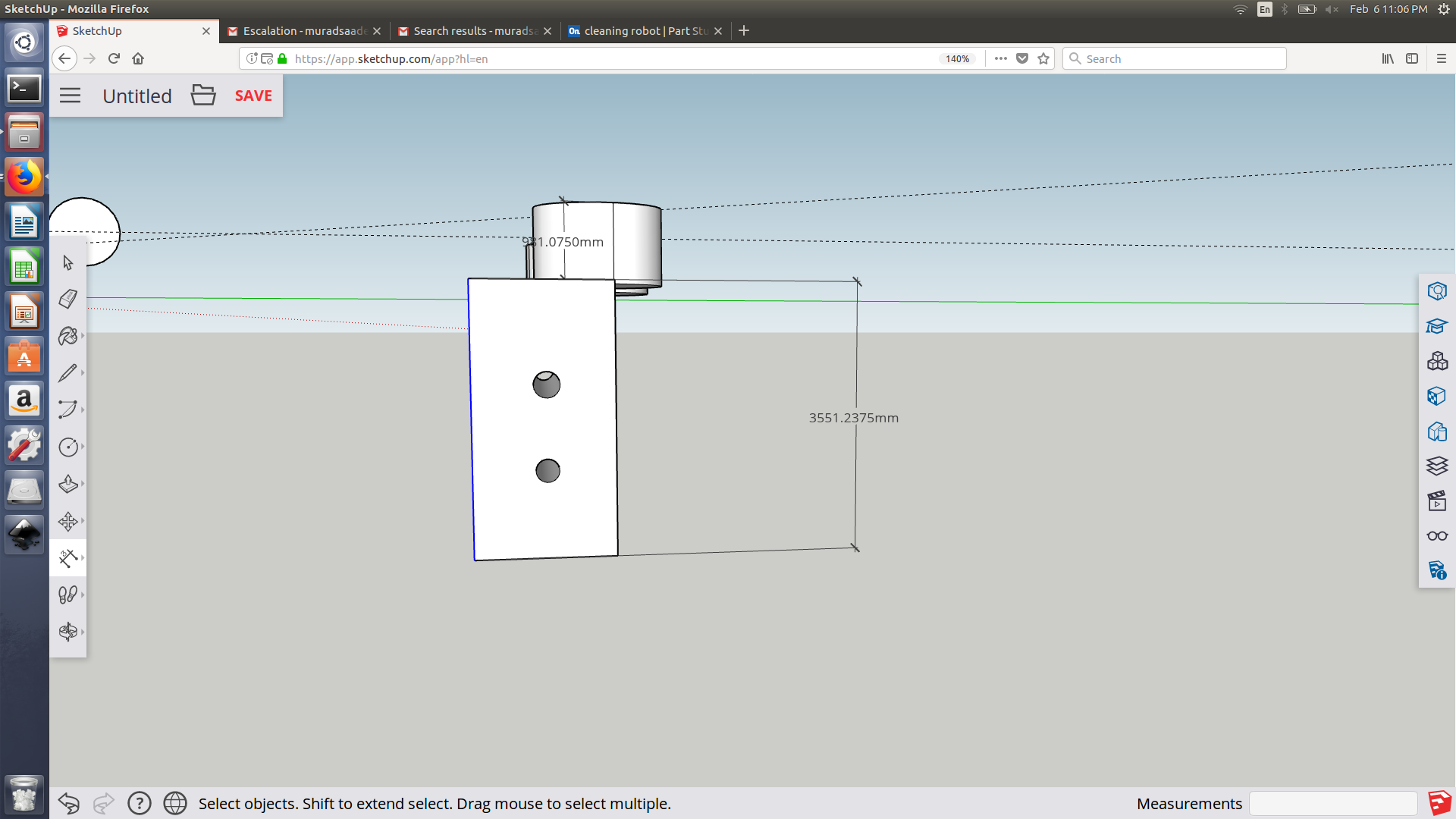
I have used online sketch up as a fast try out of sketch up, its actually designed in a very simple language that anyone can understand for example to extrude an object in sketch up you perform pull up or pull down. I have found some difficulties trying to set length or width, you can measure them using the meter but its not editable thus its not parameteric. Another draw back of sketch up is that you cant save your designs as a stl. Sketch up is more like a tool to use to draw a rough shape of the idea in your mind.
Open scad
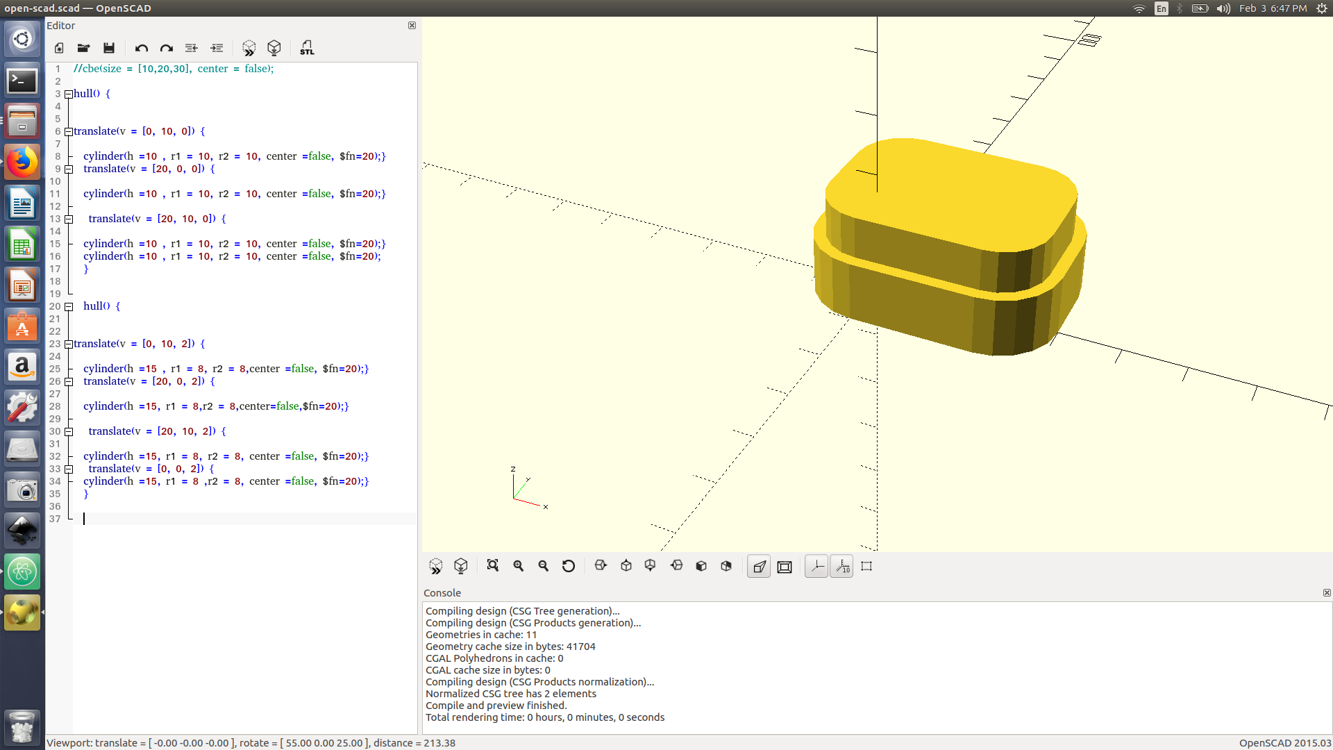
Open scad OpenSCAD, unlike many CAD products, is not an interactive modeler. Instead it is something like a 2D/3D-compiler that reads in a program file that describes the object and renders the model from this file. This gives you (the designer) full control over the modeling process. This enables you to easily change any step in the modeling process. This enables you to make designs that are defined by configurable parameters.
OpenSCAD has two main operating modes, Preview and Render. Preview is relatively fast using 3D graphics and the computer’s GPU, but is an approximation of the model and can produce artifacts; Preview uses OpenCSG and OpenGL. Render generates exact geometry and a fully tessellated mesh, it is not an approximation and as such it is often a lengthy process, taking minutes or hours for larger designs; Render uses CGAL as its geometry engine.
To access open scad manual click here
To install open scad follow the procedure available at this link
OpenSCAD has two main operating modes, Preview and Render. Preview is relatively fast using 3D graphics and the computer’s GPU, but is an approximation of the model and can produce artifacts; Preview uses OpenCSG and OpenGL. Render generates exact geometry and a fully tessellated mesh, it is not an approximation and as such it is often a lengthy process, taking minutes or hours for larger designs; Render uses CGAL as its geometry engine.
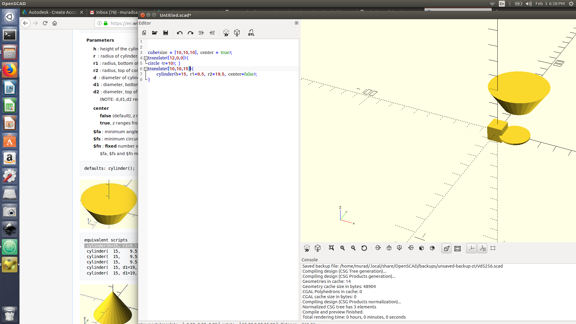
Testing around:
I am trying to have a cube and then add above it a cylinder and perform difference. I am facing some problem as the cube is not actually in the middle, I used translate ([0,0,0]) for the cube and changed the cube center to false.
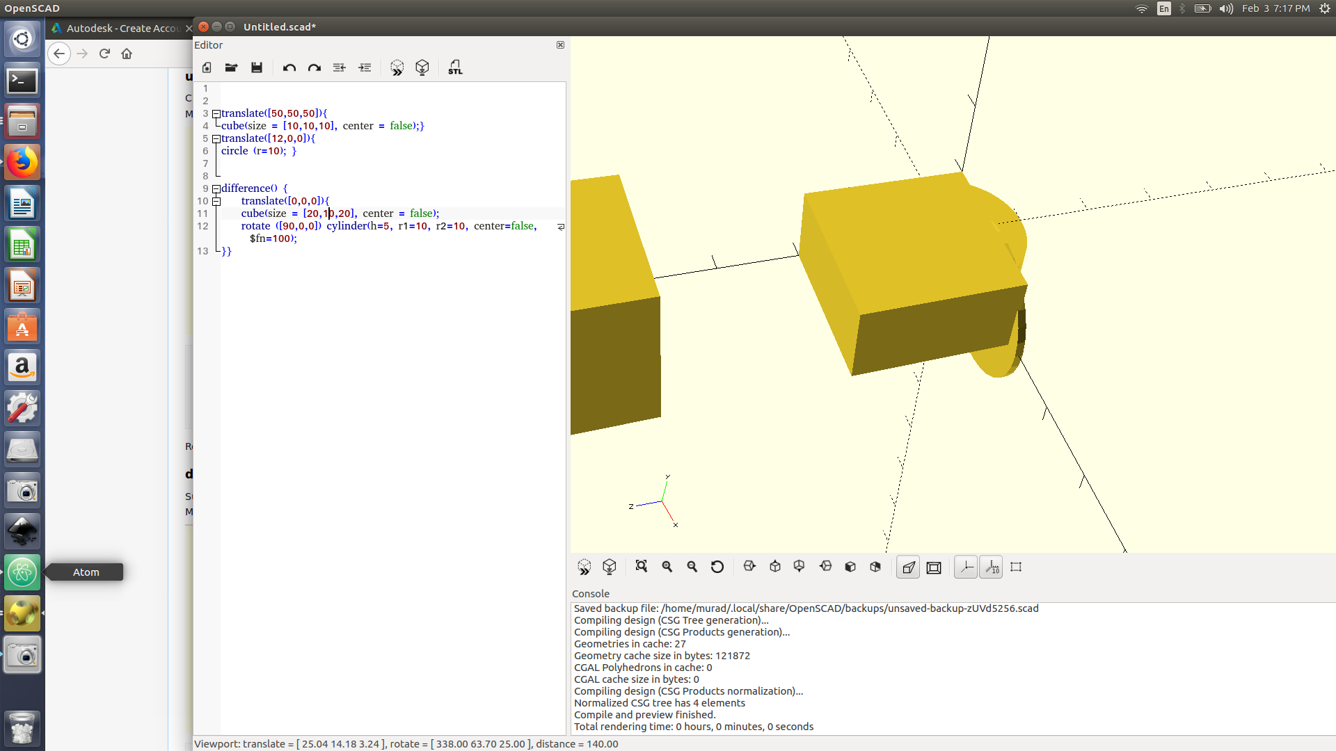
I am facing some difficulties trying to do difference ( I want to remove the square from the cylinder)
** Open scad is a wonderful tool, especially that you can do whatever you want just by typing into the screen; however for me its very time consuming as sometime a missing comma could stop the code from Previewing.**
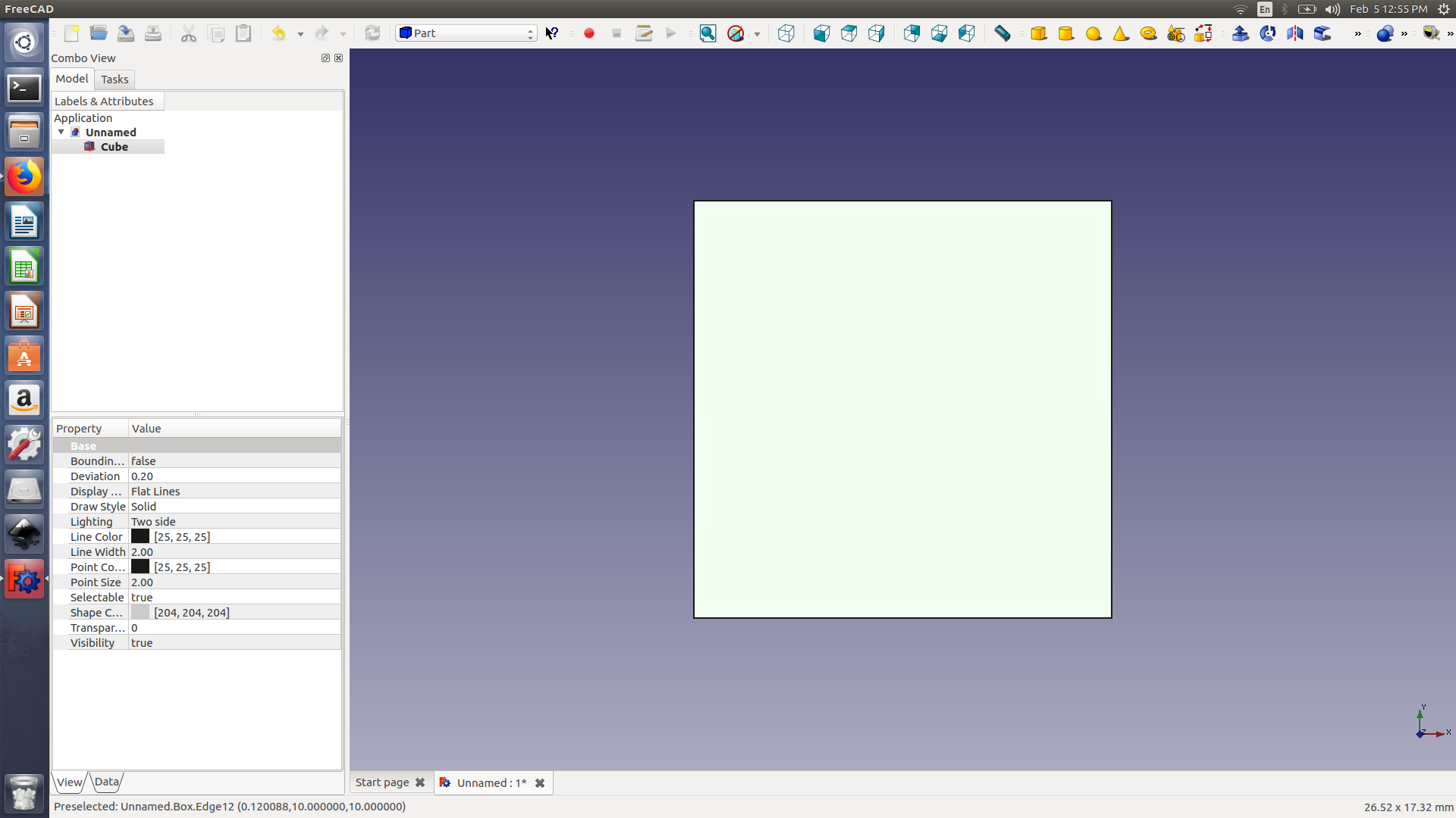
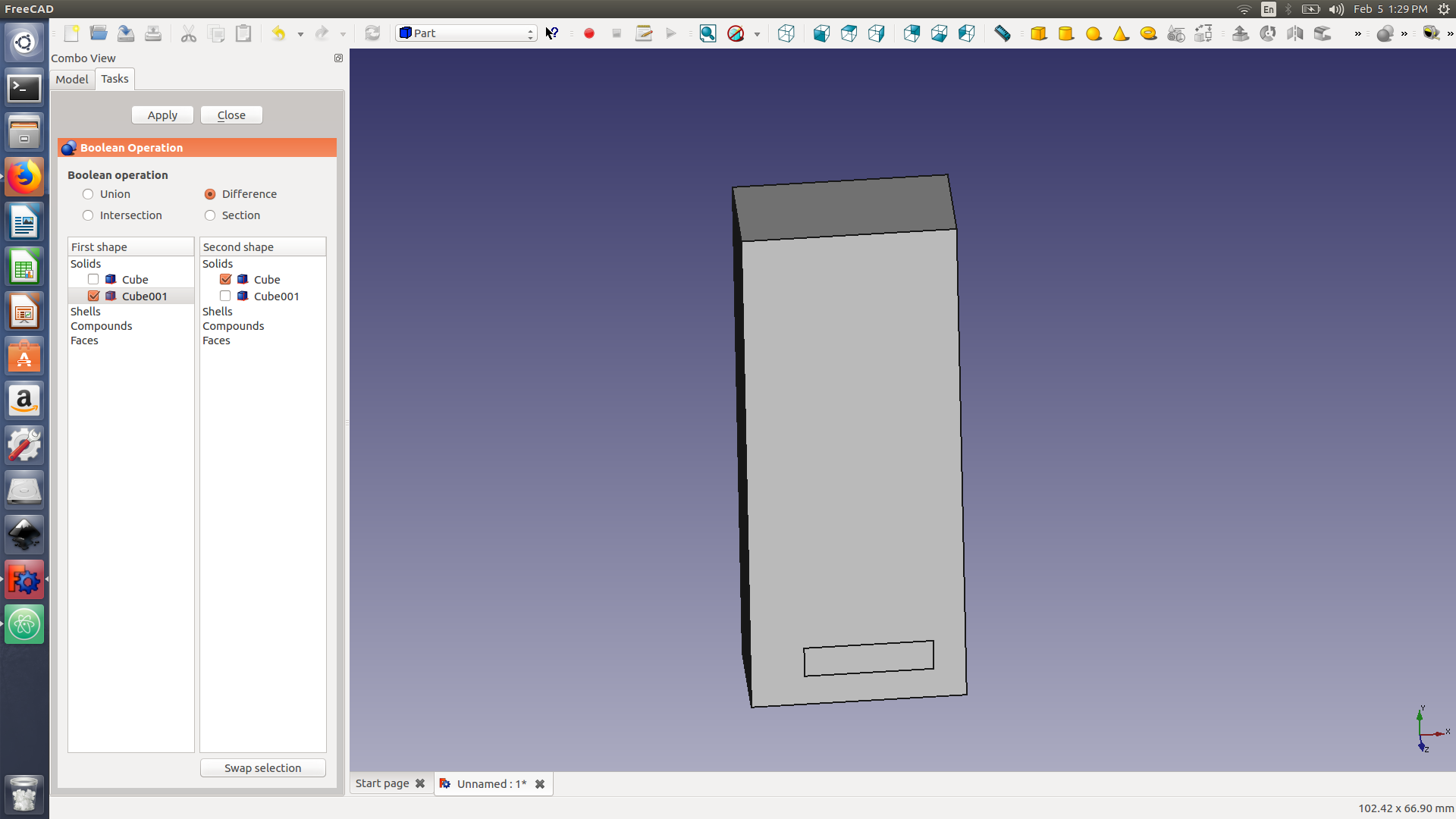
Free Cad:
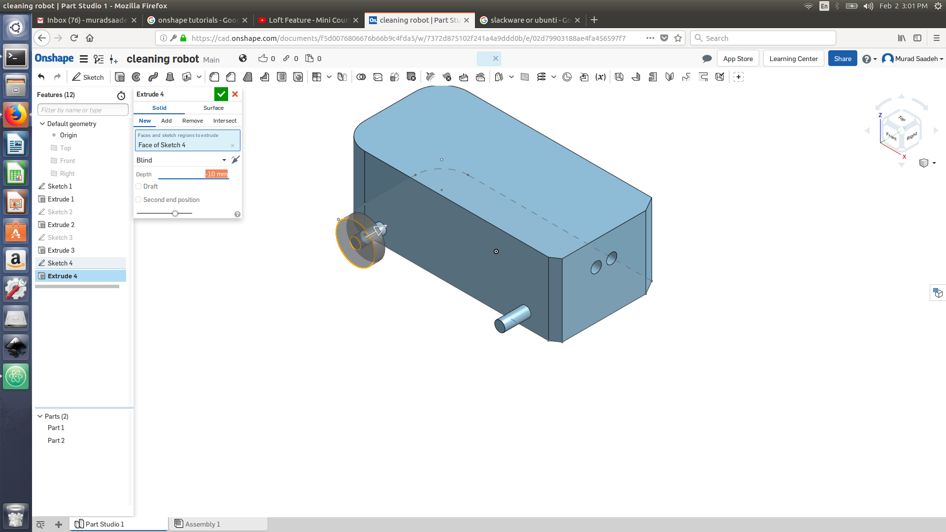
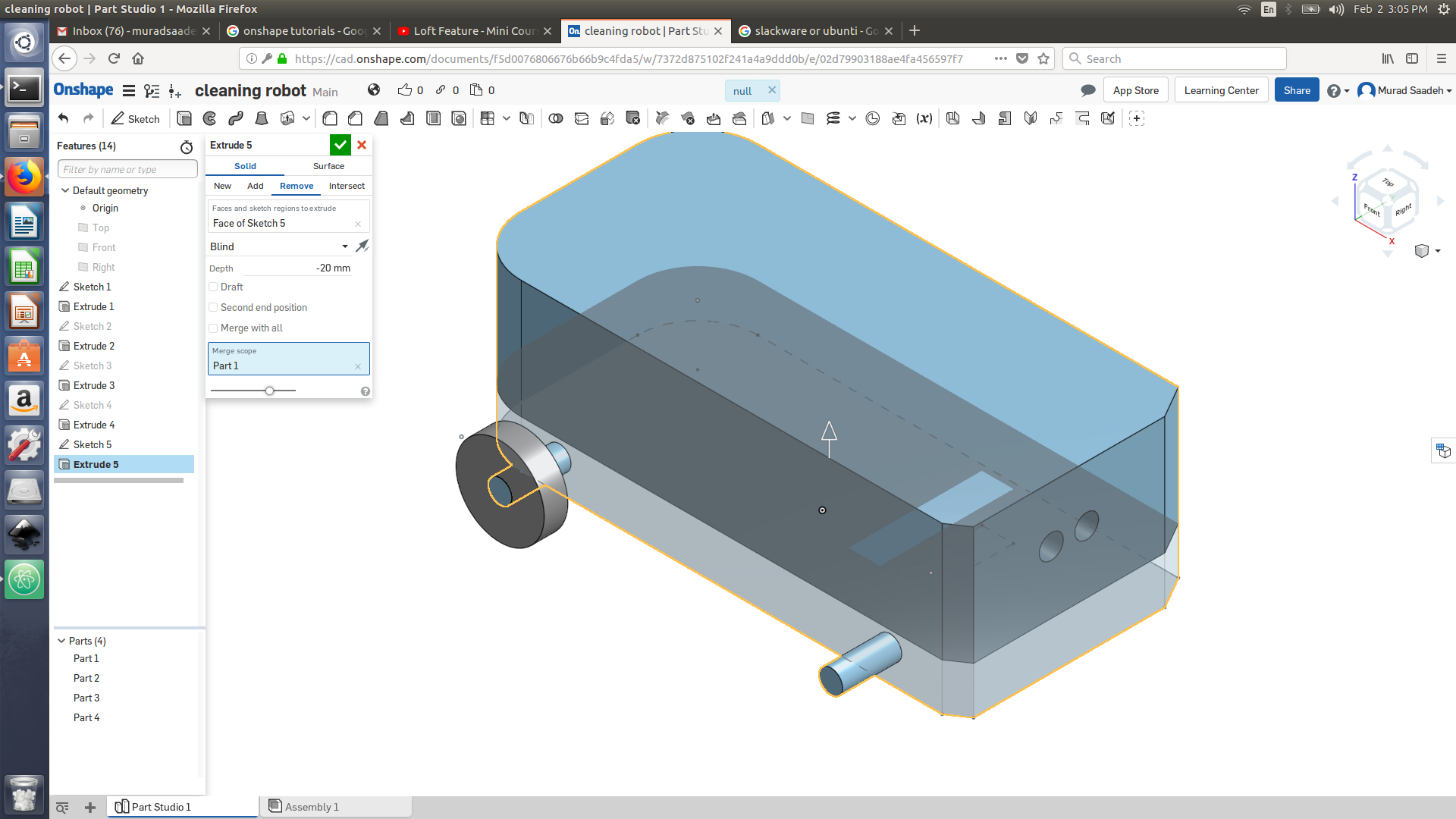
I ll be using free cad today to draw 3d model for my cleaning robot
I am trying to use the spread sheet option at open scad ( ** I forgot about that, I ll do it in the coming 2 days **)
Free cad is not very stable so you must save your work after each change as it could easily crash and loose all your data. other than that the program is really powerful specially due to the data sheet and the ability to use open scad.
Solid works
I have heard a lot of good stuff about solid works, due to the shortage of time I asked one of my colleagues Ahmed to take me on a quick tour on solid work. I have found the solid work is very close to the on-shape, the cool thing is that you don’t always have to sketch then extrude, using solid work you can press on extrude method (sweep or revolve etc) and then the sketch would open and you can draw and choose the extrude parameters and your object is ready. We have also tried performing stress and thermal simulation for the object we designed, its pretty simple however we have faced a problem performing stress analysis as we added forces on the top size without adding a surface that the object is set off on. You can choose any material while doing stress analysis ( every material data is available)
Antimony
Antimony is Parametric design software, parametric design allow us to change the object size prior to its design. Antimony software is designed by MIT for users who are just beginning to explore 3d designing.
To install Antimony Link
Anitomony home page is divided into an input and an output. The input is where you actually draw and design and the output is where you asses the final object.
2D (rectangle, ellipse, etc ) + Extrude ( revolve or loft) + difference (or union) = 3D object
Inkscape:
Today I use a very useful tool which helps you vinyl cut or prepare an image to be cut on the laser cutter. Today we had an orientation session at our Fab lab so we had to use inskscape to laser cut a lamp that Fiore has designed. Its actually pretty simple so you ll have to to open the SVG file in Inkscape and then ensure to apply red color for the items we want to cut and black color for engraving.
Wonderful stuff you can do with Inkscape:
- You can wrap a text into a shape of an object
- you can redraw you hand design objects or internet deby