Machine design week
One of the most difficult choices was to actually decide on what type of machine to make, As we already wasted the first week of this assignment in preparing for the grand opening of our lab so this left us with one week to choose, design and fabricate the machine. Unfortunately one of our colleges have decided to continue Fab Academy next year so we are only 2 students now, me, Dr.Musa. At the begging we were thinking of making a foam cutting machine using a heating element which could be very useful for our lab. However as a better learning process we did decide to make a multi purpose milling machine which later could be updated to a 3d printer or even a foam cutter. As most of the 3-axis CNC machine relay on the same working concept,thus moving a heavy milling will somehow make it easy to move a less heavier object such as heating element.
Initial plan
Initially we started by clearly describing what we need the machine to actually perform and how to reach to perfect results. We have decided to somehow adopt the design of the shopbot machine in ours
-
The machine should be able to move precisely down the x, y and z axis. To perform that we decided to use Stepper motor which is well known for high reliability, high torque at low speeds and easily controlled. The best fit for our application would be Nema 23 as it would give a better torque. We had plenty of Nema 17 stepper motors at the lab thus we ll be going to use them.
-
The second most important thing is to decide on how the motor will move the x, y and z axis, this link will show you some of the linear movement technologies link. The best linear movement that could work for us are either a rail and pinion or screwed rod. For such an application screwed rod with ball bearing linear guide is the best. However as it really tough to find a precise screw rod and it would take ages to arrive if we order it online, we have decided to go with the other choice which is to create our own rail and pinion system with a sliding linear guide.
-
The machine outer design should be very rigid and leveled to be able to hold any type of material we place on it. For this we decided to create a tension box using 17 mm HDF wood. The tension box will help to equivalently divide the load on all areas which will make it very rigid and stable.Another tension box must be created for the bridge where the y-axis and the z-axis are placed. As for this tension box we will be using 6 mm MDF wood and cut it using the laser cutter.
-
CNC host Software and firmware, There are some very helpful software to control CNC machines, like repetier and marlin. Some printers like lulzbot do actually use marlin software. I have reached a bit and I really did like repetier user friendly configuration setup for the firmware link. and its very easily linked and amended on Arduino IDE.
-
Motor driver circuits, I have actually fabricated a pcb to control stepper motor for the output week assignment. The initial plan was to actually fabricate a customized ramp 1.4(CNC shield) and have my PCB circuits attached to it. Due to the shortage of time we did buy rampp 1.4 and motor driver from the market for about 30 $.
-
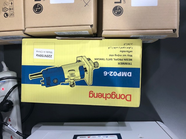
The cnc rotor. we bought an actual drill and wanted to put it but it was very heavy and then we decided to try a less heavier drill at the begging so we decided to use the dremel.
Designing the rail
We have updated Dayvik rhino machine file to match our requirement, we choose Nema 17 as our stepper motor and we have changed the maxiuimm length of our machine to 600 mm. Once we got the new machine design we have took the rail as 2d dxf file and created holes for M4 screws for the rail to stick it to the actual tension box. In dyvik machine design file the sliding rail is attached to the rail, however Sibu have helped us to create a separate sliding rail.
- Our machine design


Cutting the rails
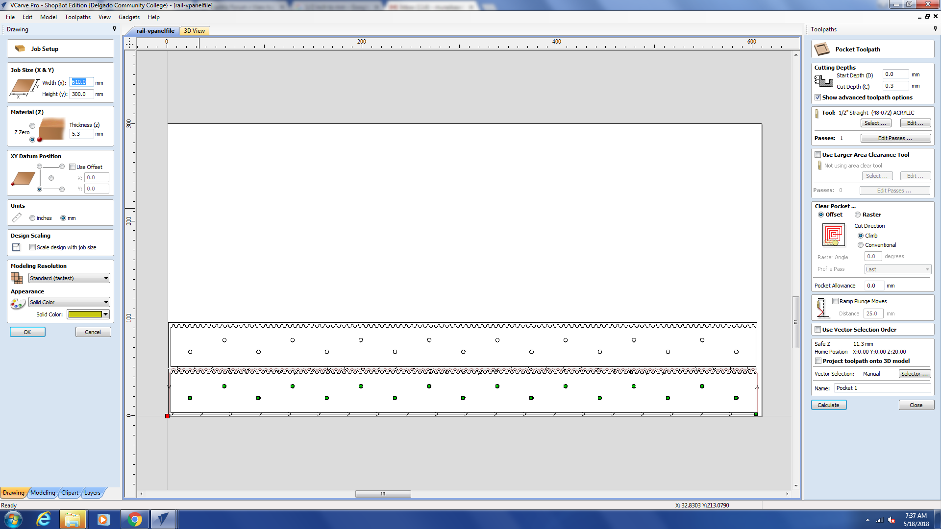
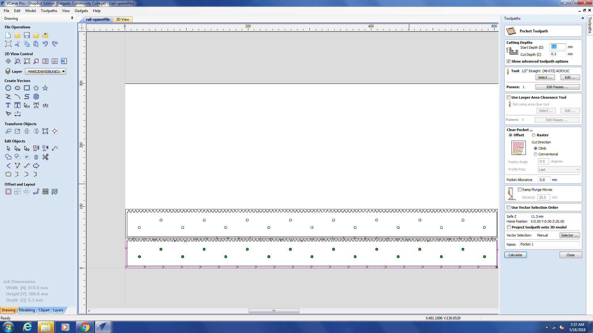
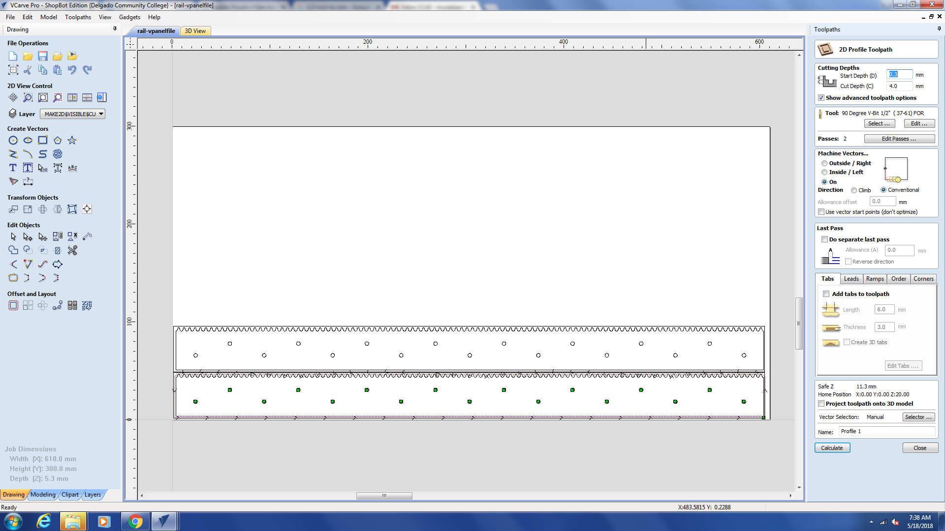
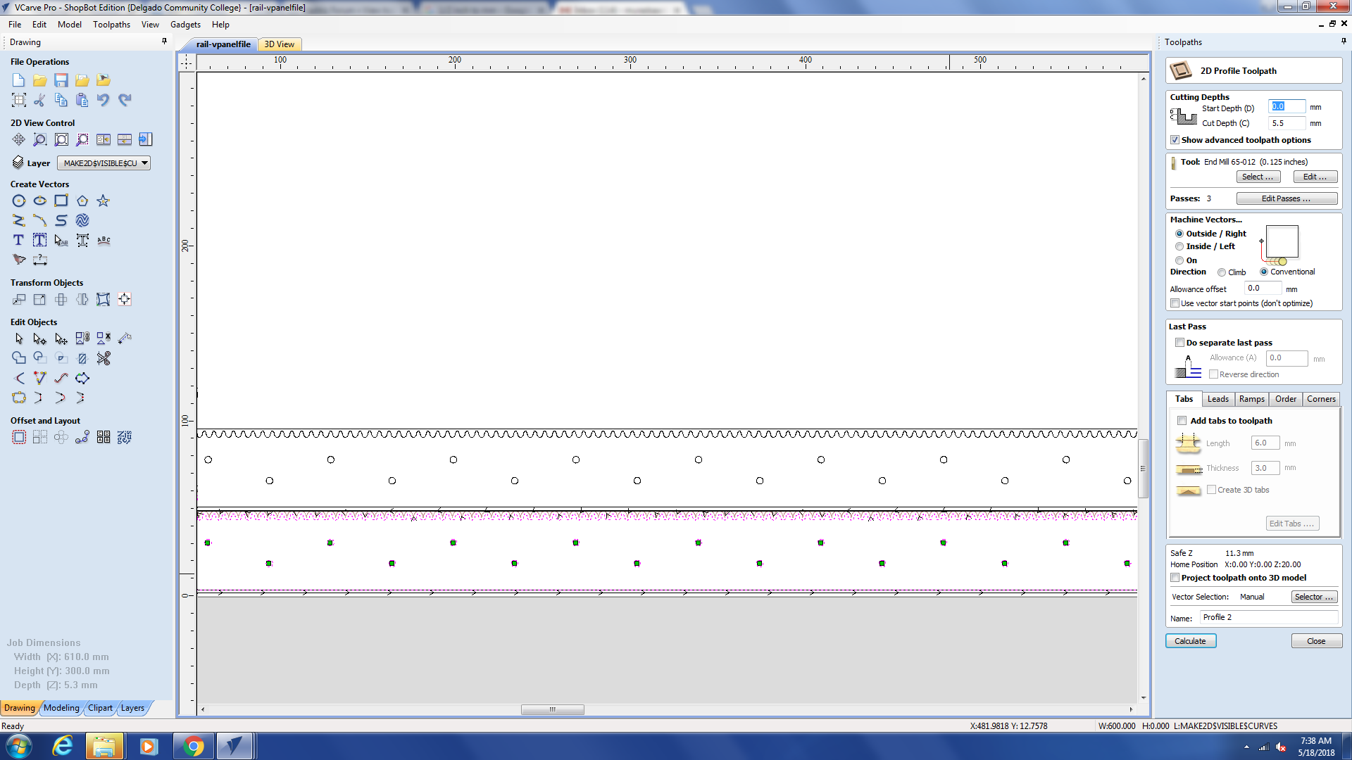
We have decided to use the acrylic available at our lab to make the rails, for a precise cut we ll cut it on the shop-bot.As we have actually tried cutting it on the laser cutter and the actual rail wasn’t perfectly cut as one side of the slot was way deeper than the other side, this is is due to the laser cutting mechanism. At the beggining we noticed that the acrylic sheet thickness wasn’t the same as from one end its 6 mm and from the other end its 5.6mm, thus we have to surface clean the acrylic sheet and set it to be 5 mm. Then we used the 90 degree bit to chamfer the side of the rail. then we used a 1/8” bit to drill the holes and cut the profile. We have repeated the same procedure for both rail and the sliding rail.
- V carve software to cut on shopbot

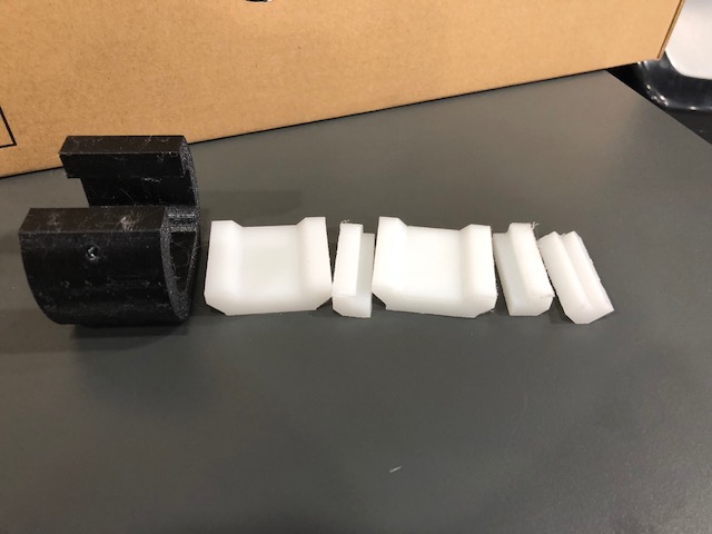
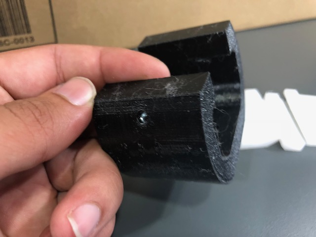
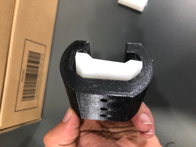
sliding blocks
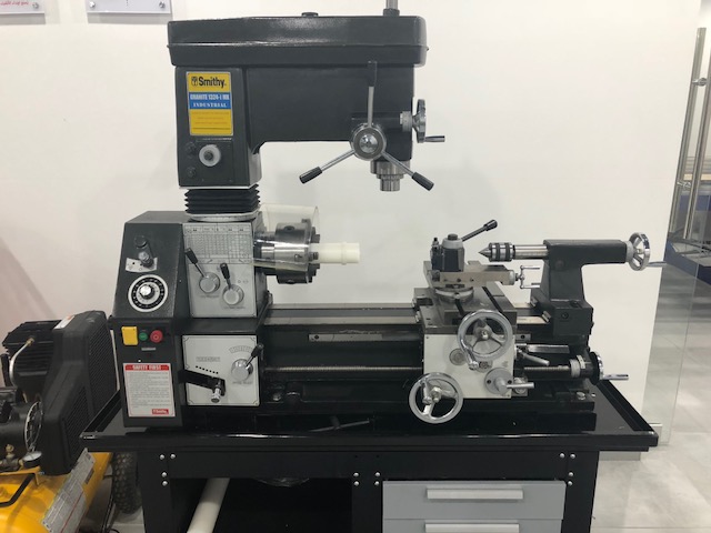
For the sliding block we have decided to use teflon material for the inner sliding surface as teflon would slide well on acrylic, for the outer holder we 3d printed them metal inserted the the hux nut while its printing to be able to stick the screws to them. For milling teflon we initially wanted to cut it using the SRM-20 machine, however as we cant actually increase the speed, we decided to use the shop-bot. not to forget the teflon block we had wasnt stable so we used a manual CNC to flatten it. It was kind of dangerous (do not try it ) but for the small teflon block we did cut them using shopbot where we did operate it manually. To manually insert nuts to the 3d printing file, we had to stop and insert the nuts manually with the use of heat gun to fit in perfectly then resume the print. This could be easily done on Zortrax M300 software Z suit, however for the ultimaker 3 everytime we add a pause the machine gets crazy, Sibu has fixed this issue by changing the actual G-code.


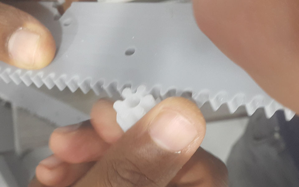
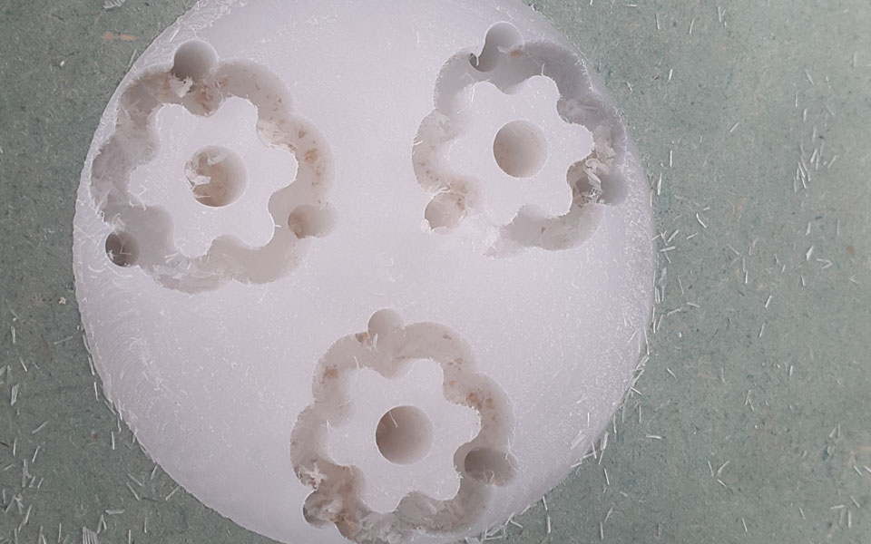
pinion
we have took the penion design from dyvik machine file and then cut it using teflon for a better sliding on acrylic. It was cut on the shop-bot.
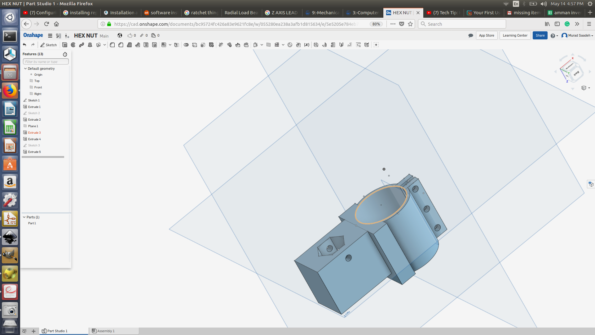
lead screw and dremel holder design
As we decided to test the lead screw to move the z-axis of the machine, I did design a dremel holder where the hex will have a hex thaat will be attached to the lead screw. In order to have a more stable design we did add the design of how it will hold to y-axis in one file and 3d printed it. The results weren’t as what we expected, this was because the 2 linear rods were attached to the lead screw part. Having them separate will give more stability to the z-axis.
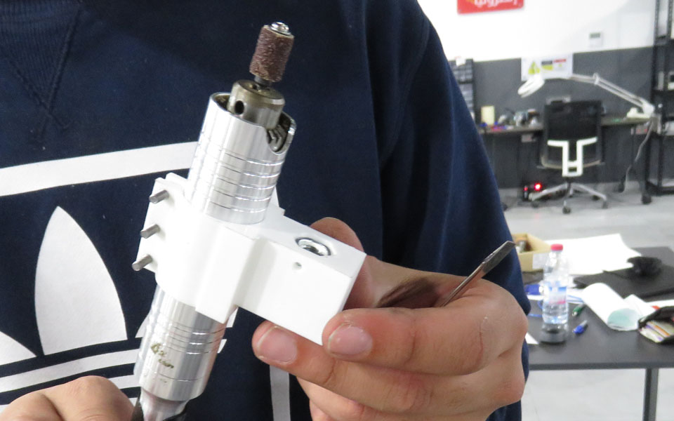
- Holder design and 3d printed model

Stepper motor controller
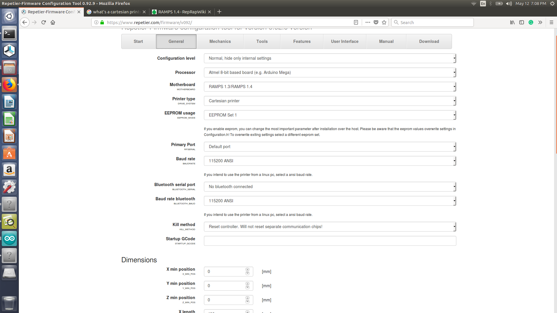
We are going to use arduino mega and ramp 1.4 and motor driver to control our Nema 17 stepper motors. For the software we will be using repetier firmware. It kind of straight forward to configure the firmware Repetier firmware, or you can manually update it from arduino ide. Repetier also offer a host software in order to connect it to your machine where you could use it to control your machine.
- Ramp 1.4

- Repetier firmware configuration
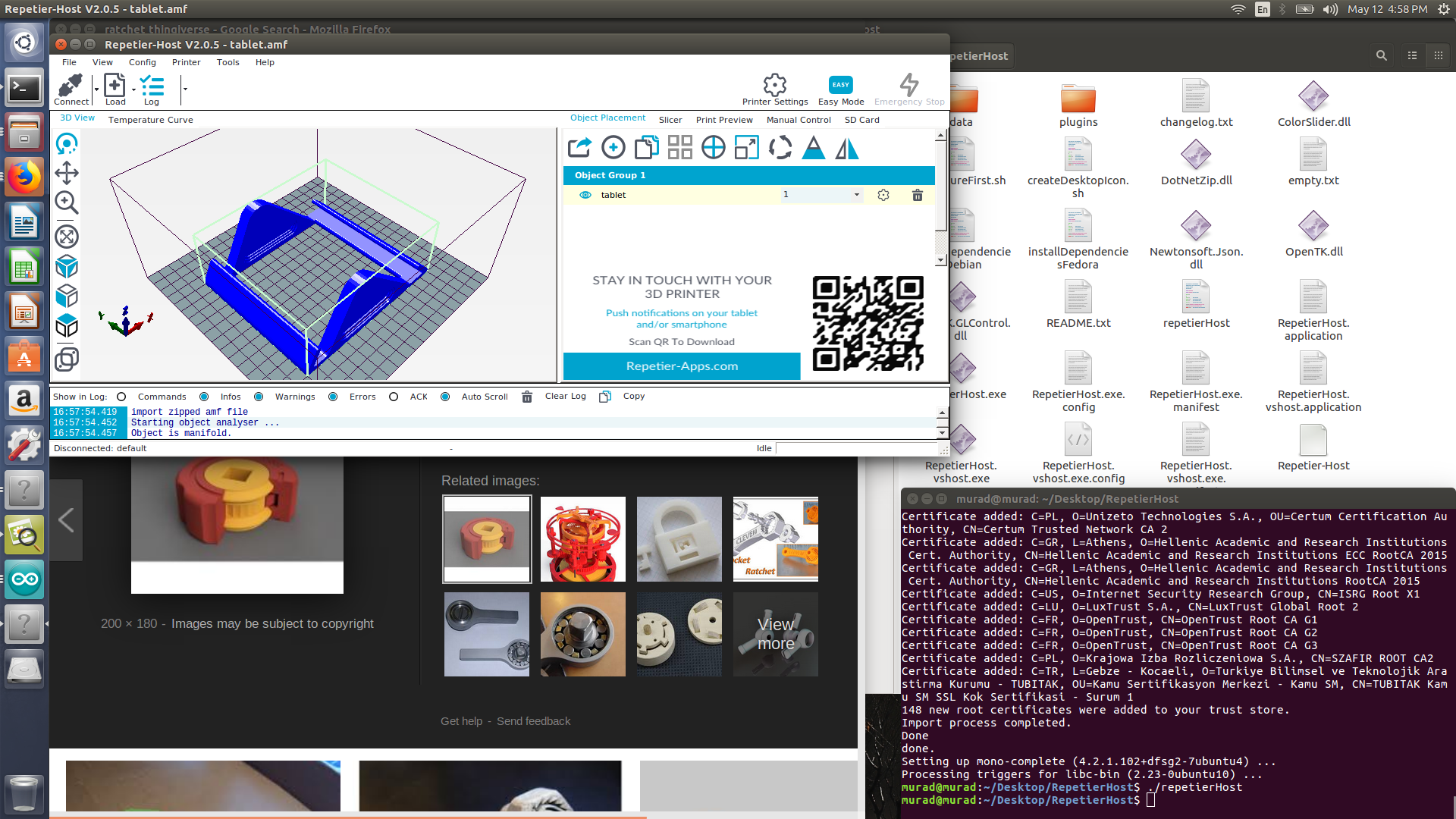
- Repetier host software
Its a very user friendly software, and give the user the flexibilty to amend a lot
 s
s
Notes:
- make sure to set the step per mm correctly as it wont be easily changed after configuring the file and you will need to EPROM to different one.
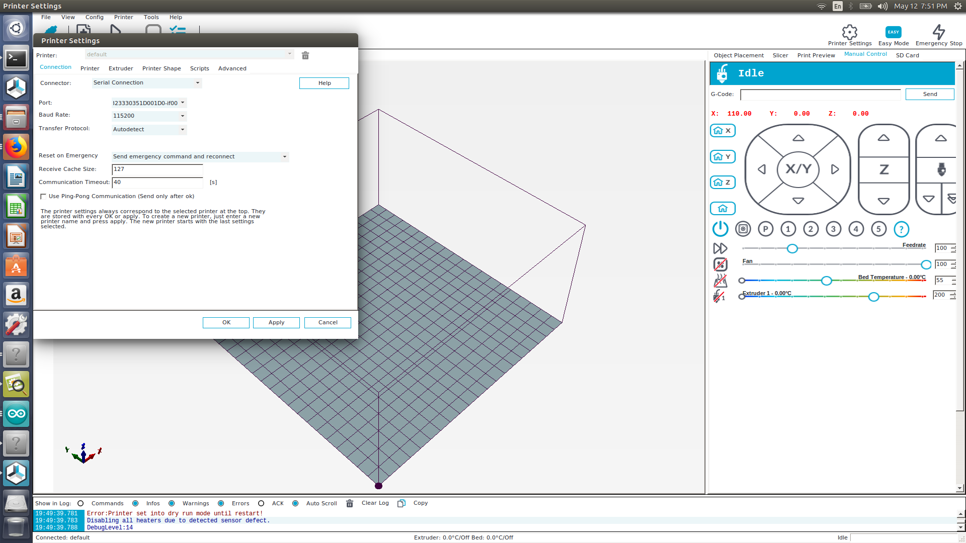
- Ensure the the baud rate is set to 115200
- If you need to change the code you must amend the ERPOM1 to a different one, as changes wont be saved
Testing
We did some test on the x-axis to ensure that the machine is moving smoothly and capable of moving with a the dremel attached to it. The repetier host software interface I could move the machine 50 mm at once, we did that and we got a result of 48.16 mm


How to improve
- Dont use acrylic as its kind of rough
- the y-axis stepper motor was missing alot of step
- z-axis linear guide weren’t actually helping and the dremel wasnt going up and down, we ll need to separate the linear guide from the dremel holder.