Network and communication
For this week I ll be using the Wifi module ESP8266 to communicate
ESP8266
ESP8266 could be used as a station where a station is device that connects to Internet via an access point (AP), where each access point is identified by an SSID. On the other hand, ESP8266 could be used as a soft access point (SAP) thus other station can be connected to the ES8266. Transport either TCP or UDP can be used. UDP enable message to be sent and received but with no visual track if the message was actually received at the other end.
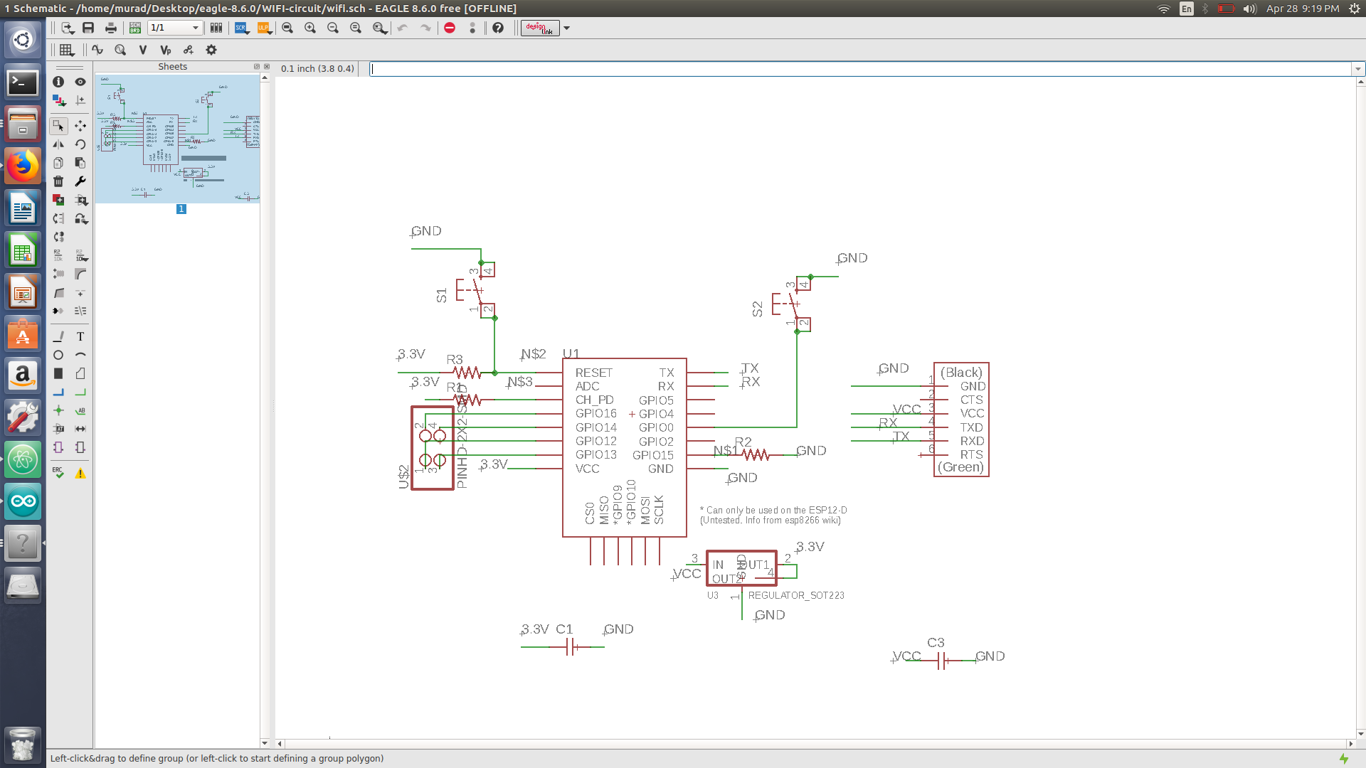
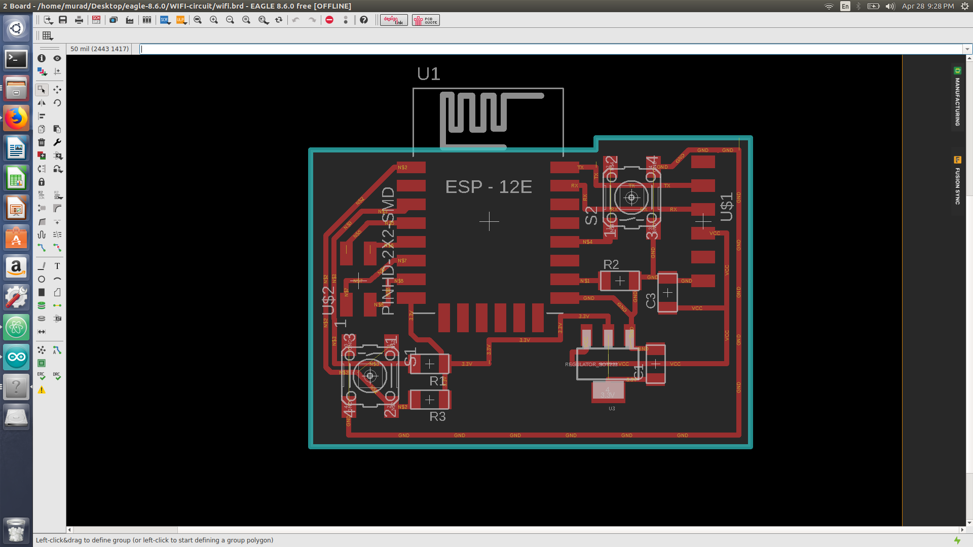
ESP8266 circuit
one of the most important thing before designing the ESP8266 is to know that ESP8266 runs on 3.3V, thus a regulator is a must. I ll be connecting my wifi module via FTDI cable.
Notes:
-
reset is connected via resistor (3k - 10 k) to 3.3V, where also the reset is connected to ground via a switch. so if a reset is required the button must be pressed
-
CH_PD which is the wifi module enabler pin, it must be connected to 3.3V
-
GPI00 is to be connected via a switch to ground, in order to flush the wifi when needed to burn a new code.
-
Capacitor to be placed between the 3.3V and GND, and also between the 5v and ground
-
TX is connected to the FTDI RX
-
RX is connected to the FTDI TX
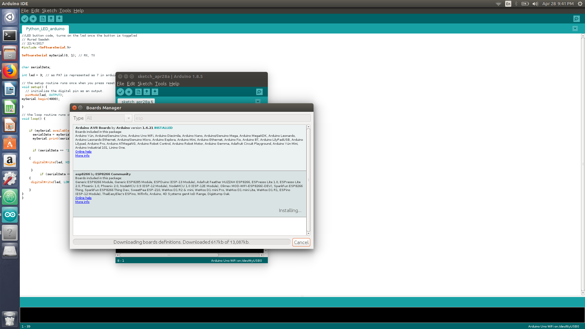
Adding ESP8266 to Arduino
- from system prefrences add this link
http://arduino.esp8266.com/stable/package_esp8266com_index.json - go to board manager and install the ESP8266 library
- You ll find plenty of helpful examples regarding the ESP8266 available on arduino ide once the library is installed
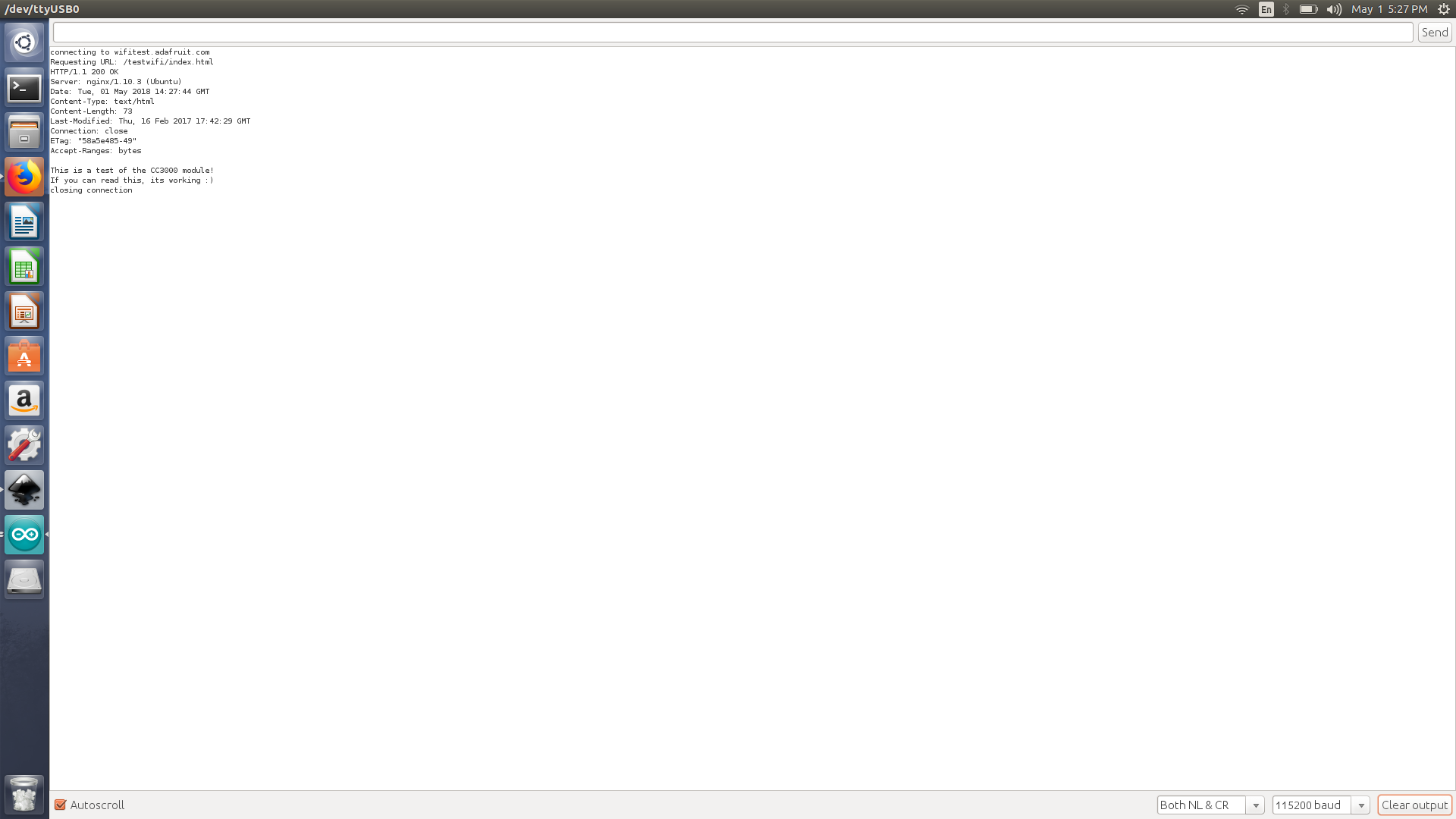
My first test to check if the module was connected and working define
- test code
/*
- Simple HTTP get webclient test */
#include
const char* ssid = “hotpi”; const char* password = “testthis”;
const char* host = “wifitest.adafruit.com”;
void setup() { Serial.begin(115200); delay(100);
// We start by connecting to a WiFi network
Serial.println(); Serial.println(); Serial.print(“Connecting to “); Serial.println(ssid);
WiFi.begin(ssid, password);
while (WiFi.status() != WL_CONNECTED) { delay(500); Serial.print(“.”); }
Serial.println(“”);
Serial.println(“WiFi connected”);
Serial.println(“IP address: “);
Serial.println(WiFi.localIP());
Serial.print(“Netmask: “);
Serial.println(WiFi.subnetMask());
Serial.print(“Gateway: “);
Serial.println(WiFi.gatewayIP());
}
int value = 0;
void loop() { delay(5000); ++value;
Serial.print(“connecting to “); Serial.println(host);
// Use WiFiClient class to create TCP connections WiFiClient client; const int httpPort = 80; if (!client.connect(host, httpPort)) { Serial.println(“connection failed”); return; }
// We now create a URI for the request String url = “/testwifi/index.html”; Serial.print(“Requesting URL: “); Serial.println(url);
// This will send the request to the server client.print(String(“GET “) + url + “ HTTP/1.1\r\n” + “Host: “ + host + “\r\n” + “Connection: close\r\n\r\n”); delay(500);
// Read all the lines of the reply from server and print them to Serial while(client.available()){ String line = client.readStringUntil(‘\r’); Serial.print(line); }
Serial.println(); Serial.println(“closing connection”); }
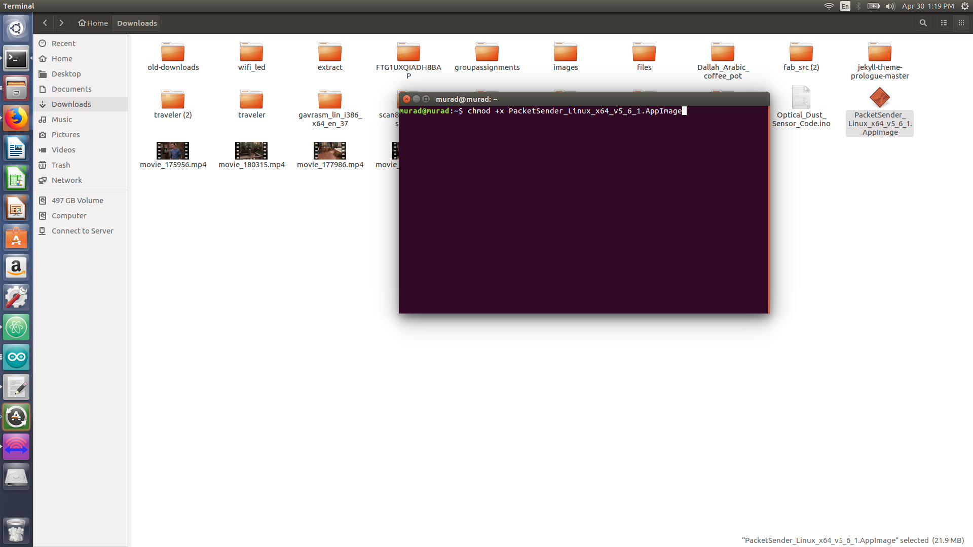
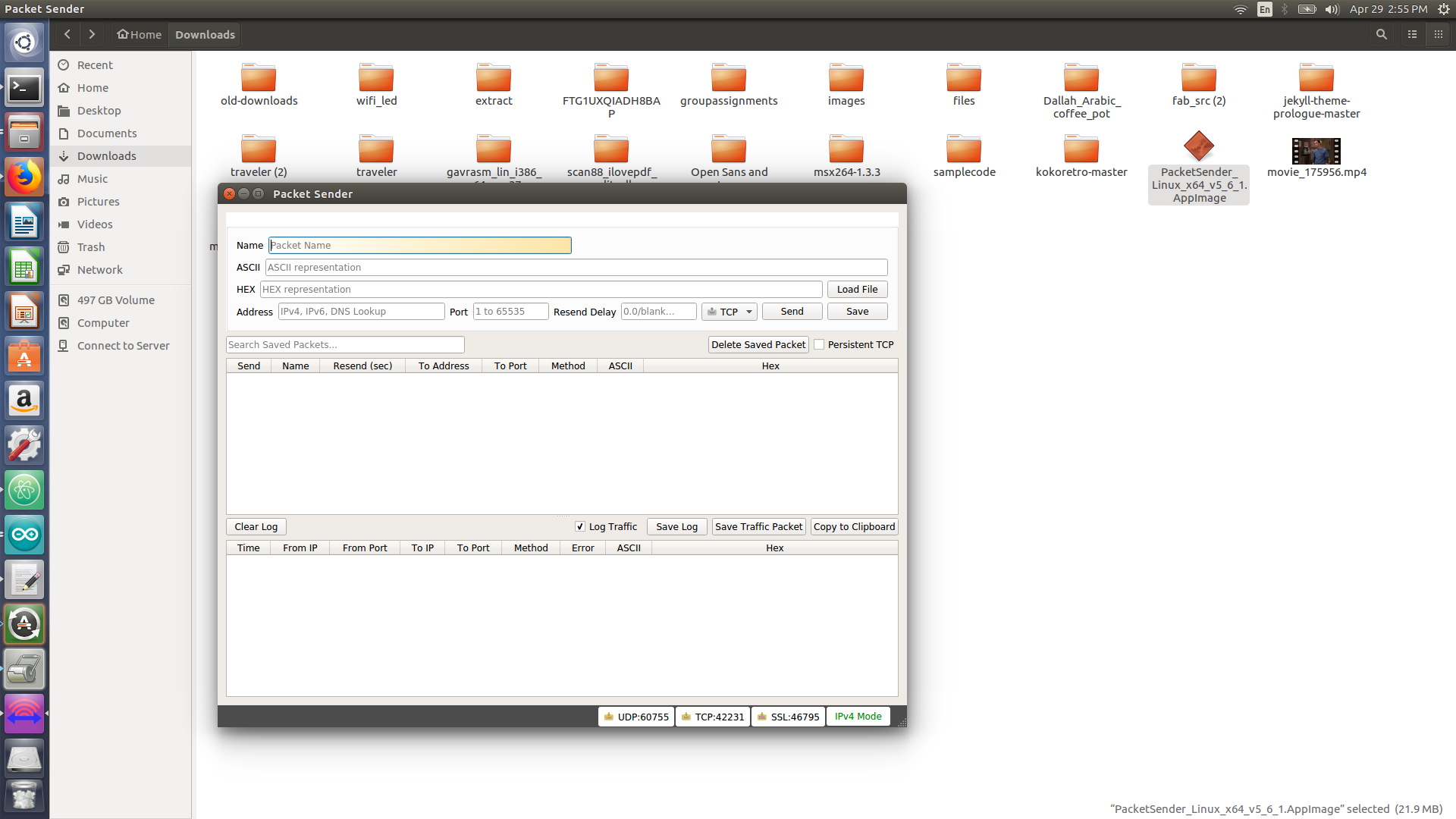
Packet sender
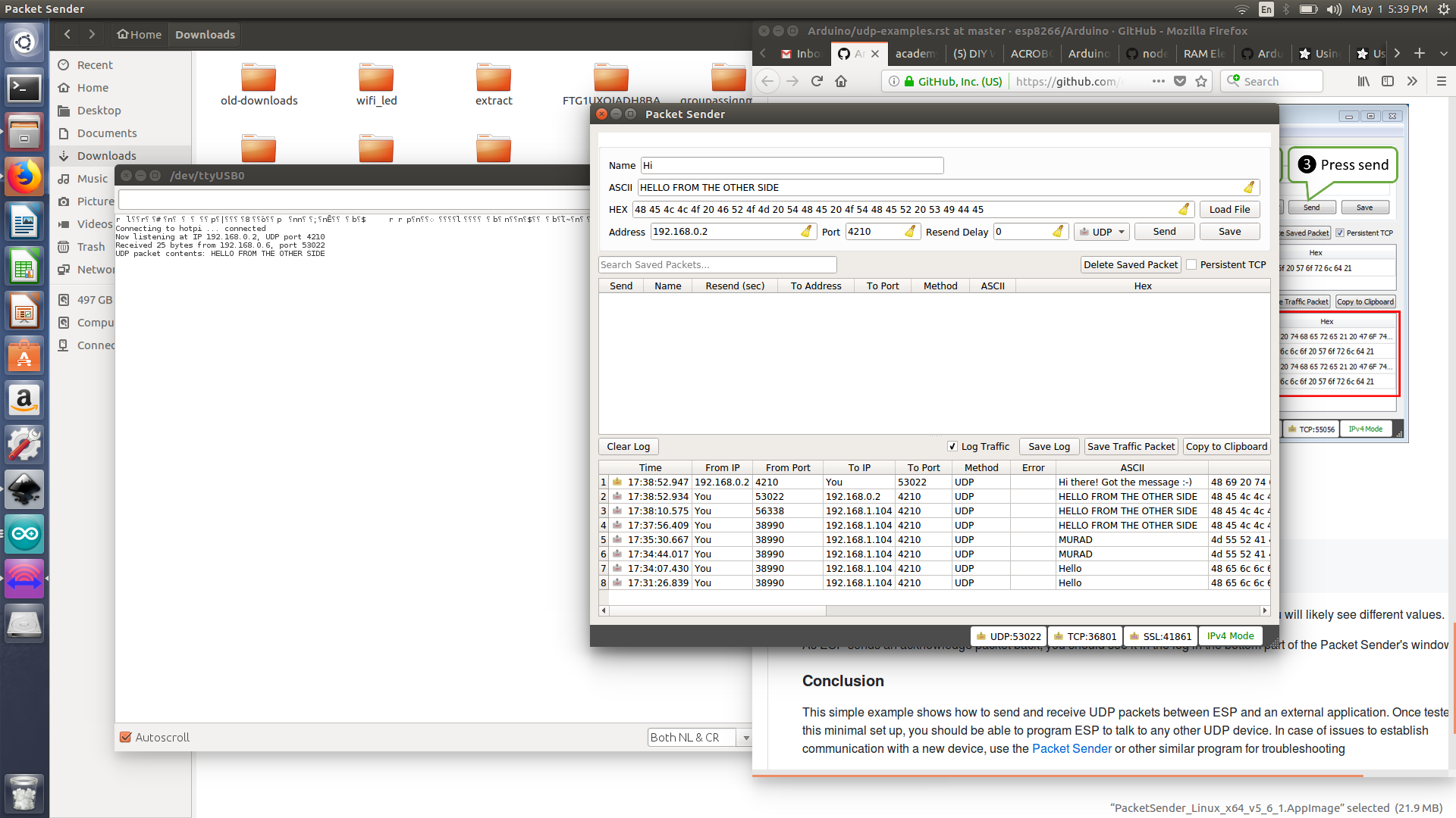
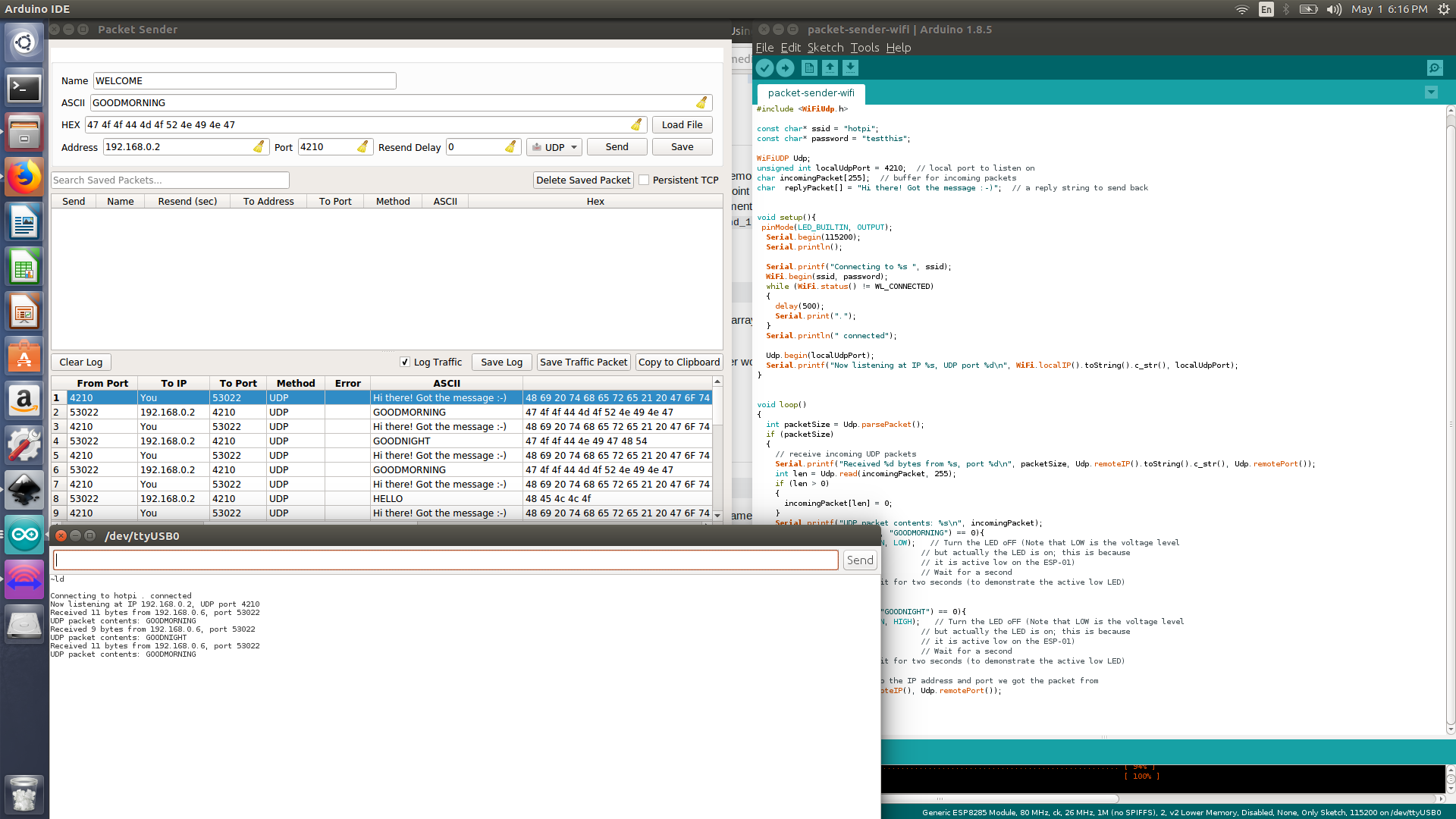
Arduino code to receive packets
My first code will allow me to send packets from my laptop to control the built in LED on the ESP8266 wifi module, I have used the code available at this wonderful ESP8266 documentation (link)[https://github.com/esp8266/Arduino/blob/master/doc/esp8266wifi/udp-examples.rst] and I have updated the code to recieve specific packet and turn on and off the LED. I ll be using UDP transport method to achieve that.
// sending and recieving packets from my laptop to the ESP8266 which will control the ESP built in LED
//Murad Saadeh

#include <ESP8266WiFi.h>
#include <WiFiUdp.h>

const char* ssid = "hotpi";
const char* password = "testthis";

WiFiUDP Udp;
unsigned int localUdpPort = 4210;  // local port to listen on
char incomingPacket[255];  // buffer for incoming packets
char  replyPacket[] = "Hi there! Got the message :-)";  // a reply string to send back


void setup(){
 pinMode(LED_BUILTIN, OUTPUT);
  Serial.begin(115200);
  Serial.println();

  Serial.printf("Connecting to %s ", ssid);
  WiFi.begin(ssid, password);
  while (WiFi.status() != WL_CONNECTED)
  {
    delay(500);
    Serial.print(".");
  }
  Serial.println(" connected");

  Udp.begin(localUdpPort);
  Serial.printf("Now listening at IP %s, UDP port %d\n", WiFi.localIP().toString().c_str(), localUdpPort);
}


void loop()
{
  int packetSize = Udp.parsePacket();
  if (packetSize)
  {
    // receive incoming UDP packets
    Serial.printf("Received %d bytes from %s, port %d\n", packetSize, Udp.remoteIP().toString().c_str(), Udp.remotePort());
    int len = Udp.read(incomingPacket, 255);
    if (len > 0)
    {
      incomingPacket[len] = 0;
    }
    Serial.printf("UDP packet contents: %s\n", incomingPacket);
   if(strcmp(incomingPacket, "GOODMORNING") == 0){
    digitalWrite(LED_BUILTIN, LOW);   // Turn the LED oFF (Note that LOW is the voltage level

  delay(1000);                      // Wait for a second

}

 if(strcmp(incomingPacket, "GOODNIGHT") == 0){
    digitalWrite(LED_BUILTIN, HIGH);   // Turn the LED oFF (Note that LOW is the voltage level

  delay(1000);                      // Wait for a second

}
    // send back a reply, to the IP address and port we got the packet from
    Udp.beginPacket(Udp.remoteIP(), Udp.remotePort());
    Udp.write(replyPacket);
    Udp.endPacket();
  }
}
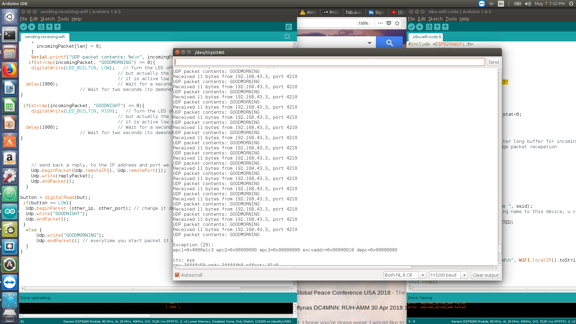
Sending and receiving UDP packets between 2 ESP8266 modules
I did communicate between 2 ESP8266 modules, where once a button is pressed a packet is sent which will lid the LED on the other module and vice versa. I have actually acheived the connection, however it kept on sending packets even when I release the button thus I must define it to send UDP once the button was in a state 0 and became 1 only. The code is very similar to the previous UDP code, you must burn this code on both ESP8266 modules (make sure you amend the ip address depending on which one you are programming )
// sending and receiving packets between two ESP8266 module, burn this code for both you modules but only change the ip address
//Murad Saadeh

#include <ESP8266WiFi.h>
#include <WiFiUdp.h>
#define but 0
#define other_ip "192.168.43.3"
#define other_port 4210


const char* ssid = "op5t";
const char* password = "aaaaaaaa";
WiFiUDP Udp;
unsigned int localUdpPort = 4210;  // local port to listen on
char incomingPacket[100];  // buffer for incoming packets
char  replyPacket[] = "Hi there! Got the message :-)";  // a reply string to send back
int button;
// add ip adress

void setup(){
 pinMode(LED_BUILTIN, OUTPUT);
 pinMode(but, INPUT_PULLUP);
  Serial.begin(115200);
  Serial.println();

  Serial.printf("Connecting to %s ", ssid);
  WiFi.begin(ssid, password);
  while (WiFi.status() != WL_CONNECTED)
  {
    delay(500);
    Serial.print(".");
  }
  Serial.println(" connected");

  Udp.begin(localUdpPort);
  Serial.printf("Now listening at IP %s, UDP port %d\n", WiFi.localIP().toString().c_str(), localUdpPort);
}


void loop()
{
  int packetSize = Udp.parsePacket();
  if (packetSize)
  {
    // receive incoming UDP packets
    Serial.printf("Received %d bytes from %s, port %d\n", packetSize, Udp.remoteIP().toString().c_str(), Udp.remotePort());
    int len = Udp.read(incomingPacket, 255);
    if (len > 0)
    {
      incomingPacket[len] = 0;
    }
    Serial.printf("UDP packet contents: %s\n", incomingPacket);
   if(strcmp(incomingPacket, "GOODMORNING") == 0){
    digitalWrite(LED_BUILTIN, LOW);   // Turn the LED oFF (Note that LOW is the voltage level
                                    // but actually the LED is on; this is because
                                    // it is active low on the ESP-01)
  delay(1000);                      // Wait for a second
                      // Wait for two seconds (to demonstrate the active low LED)
}

 if(strcmp(incomingPacket, "GOODNIGHT") == 0){
    digitalWrite(LED_BUILTIN, HIGH);   // Turn the LED oFF (Note that LOW is the voltage level
                                    // but actually the LED is on; this is because
                                    // it is active low on the ESP-01)
  delay(1000);                      // Wait for a second
                      // Wait for two seconds (to demonstrate the active low LED)
}


    // send back a reply, to the IP address and port we got the packet from
    Udp.beginPacket(Udp.remoteIP(), Udp.remotePort());
    Udp.write(replyPacket);
    Udp.endPacket();
  }

button = digitalRead(but);
 if(button == LOW){
  Udp.beginPacket (other_ip, other_port); // change it depending which one are you programming
  Udp.write("GOODNIGHT");
  Udp.endPacket();
 }
  else {
      Udp.write("GOODMORNING");
      Udp.endPacket(); // everytime you start packet it must end
  }
}
HC-05 blue-tooth module
I have read some articles and examples for connecting two HC-05 modules together. First of all the master blue-tooth module and the slave module must be defined, this is done by using the AT commands.
- Check both baud rate to be equal by
AT+UART? - define the master by changing the role to 1
AT+role=1 - Connect the master to a fix address by
AT+cmode=0, if its set to 1 it would connect to anything near it - connect the device to the slave by using the slave adress
AT+BIND= add address here - to check for the slave address
AT+ADDR?
Master arduino code
//Blinking led over Bluetooth
//MASTER code

#define ledPin 9

void setup() {
  pinMode(ledPin, OUTPUT);
  digitalWrite(ledPin, LOW);
  Serial.begin(38400); // Default communication rate of the Bluetooth module
}
void loop() {
 if(Serial.available() > 0){ // Checks whether data is comming from the serial port
    state = Serial.read(); // Reads the data from the serial port
 }
 // Controlling the LED
 if (state == '1') {
  digitalWrite(ledPin, HIGH); // LED ON
  state = 0;
 }
 else if (state == '0') {
  digitalWrite(ledPin, LOW); // LED ON
  state = 0;
 }
// Slave code

int buttonState = 0;
void setup() {
  pinMode(button, INPUT);

  Serial.begin(38400); // Default communication rate of the Bluetooth module
}
void loop() {
 if(Serial.available() > 0){ // Checks whether data is comming from the serial port
    state = Serial.read(); // Reads the data from the serial port
 }


 // Reading the button
 buttonState = digitalRead(button);
 if (buttonState == HIGH) {
   Serial.write('1'); // Sends '1' to the master to turn on LED
 }
 else {
   Serial.write('0');
 }
}
- Reference: link