Output device
For this week I ll design a circuit to control a bipolar stepper motor. At first I wanted to design my own H-bridge, however unfortunetly after I had designed and milled my H-bridge circuit, I found at that we don’t have transistors at our lab. Thus I had to design another circuit using the IC motor control (h-bridge) to control the motor.
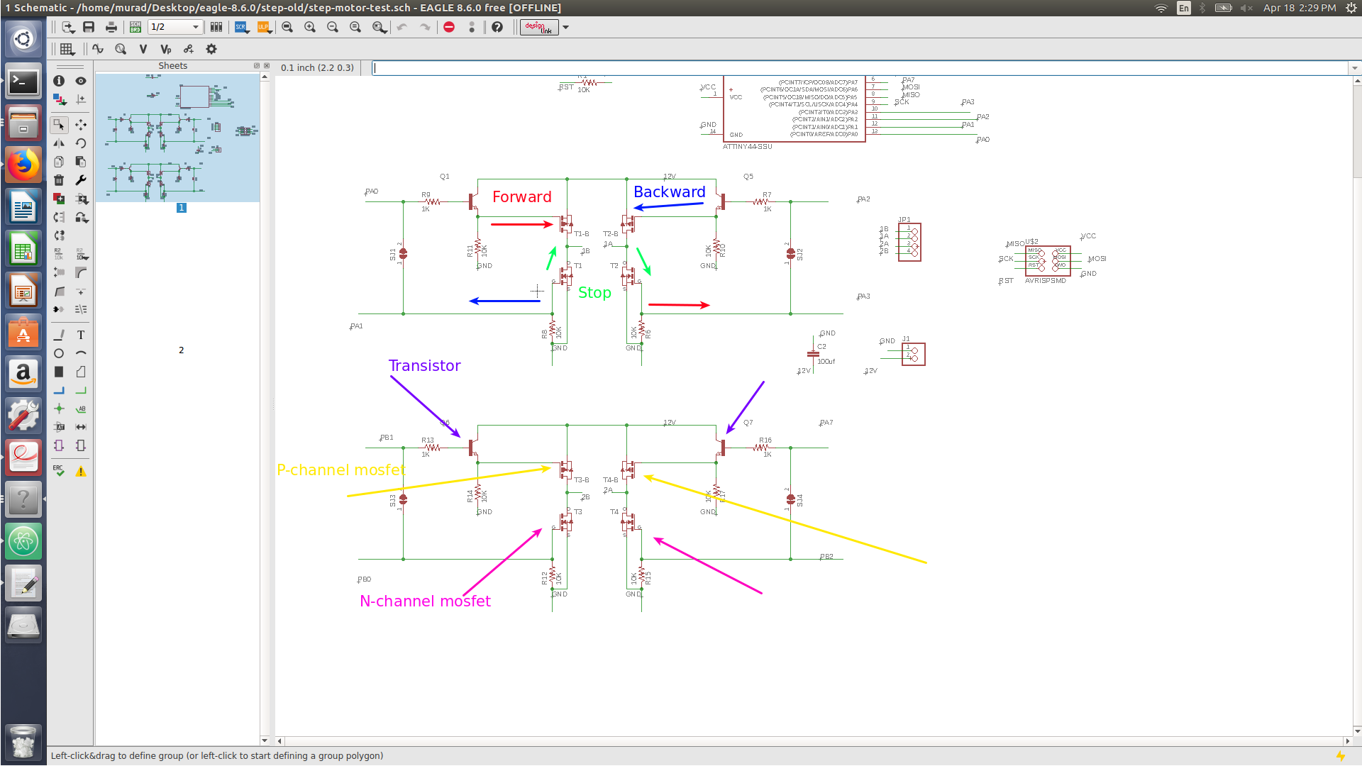
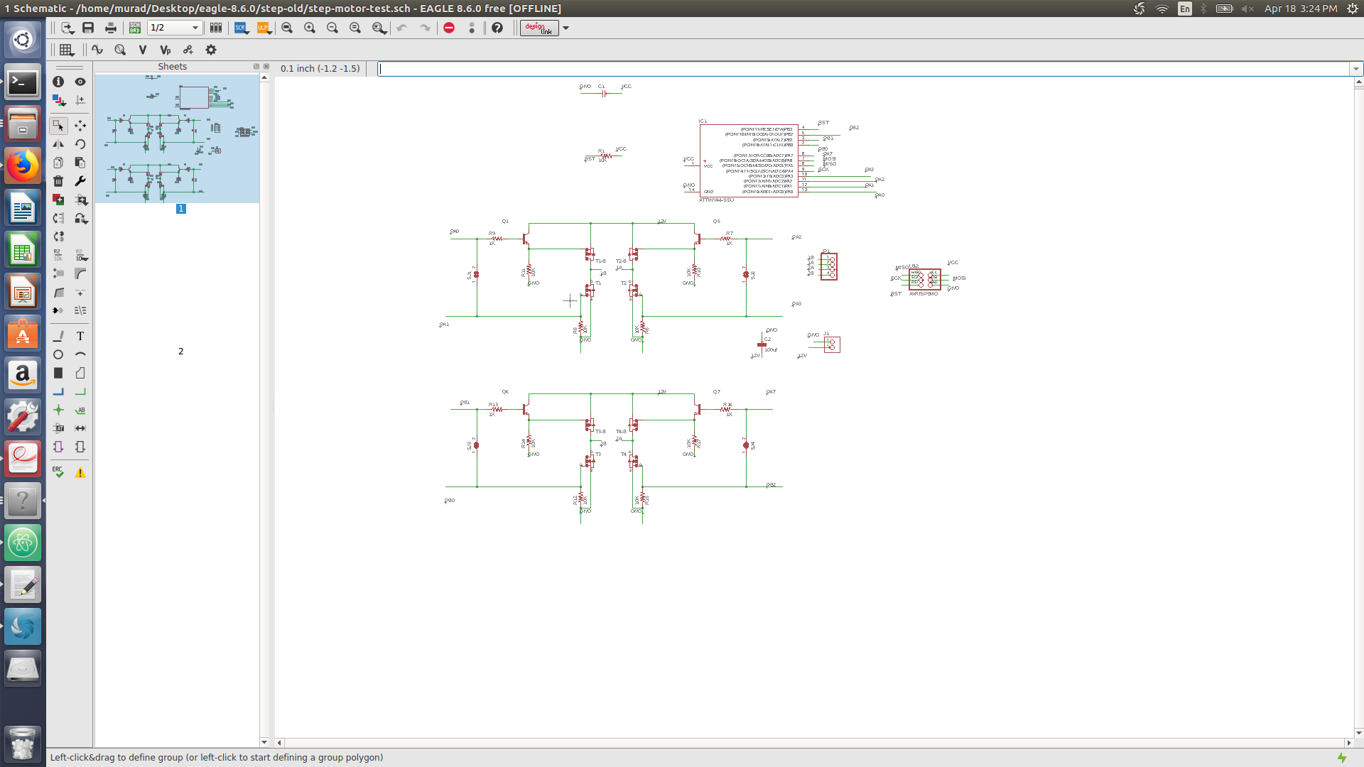
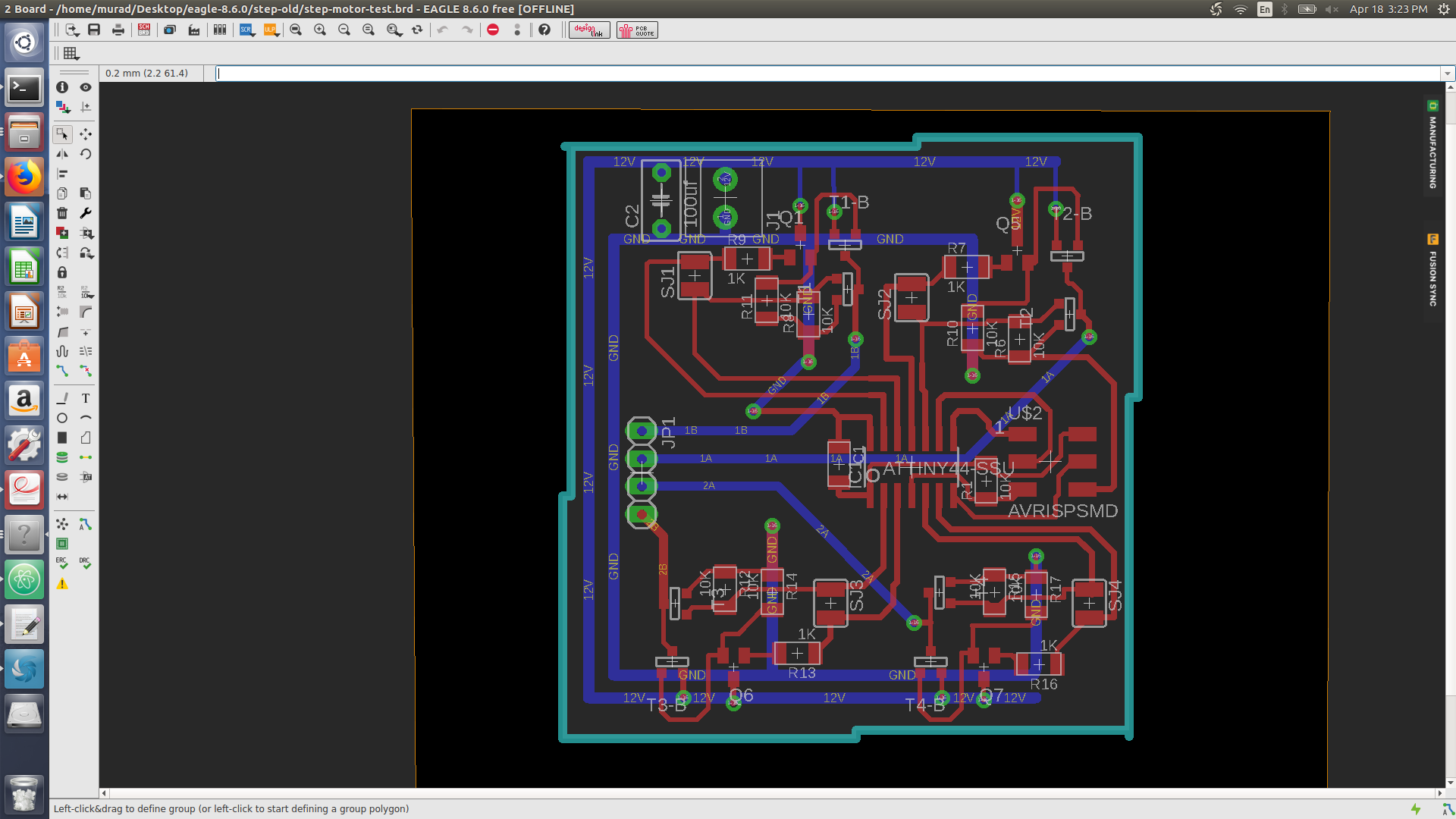
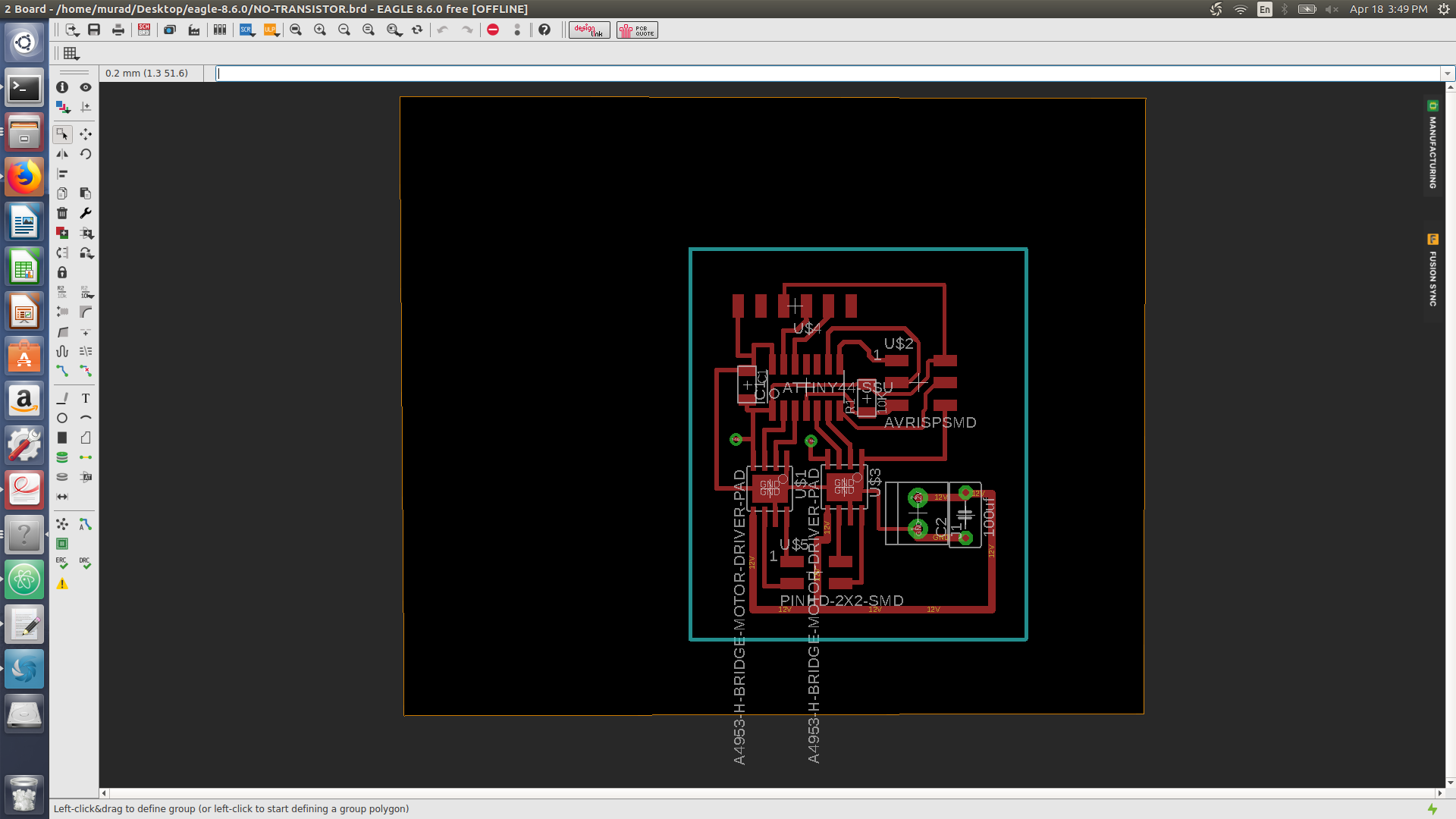
Designing H-bridge
An H-bridge consist of a 2 p-channel mosfet and one n-channel mosfet. to turn the motor one way, you would activate a p-channel mosfet with an n-channel mosfet (opposite to each other) to drive a motor one way. To stop the motor activate both n-channel mosfets.

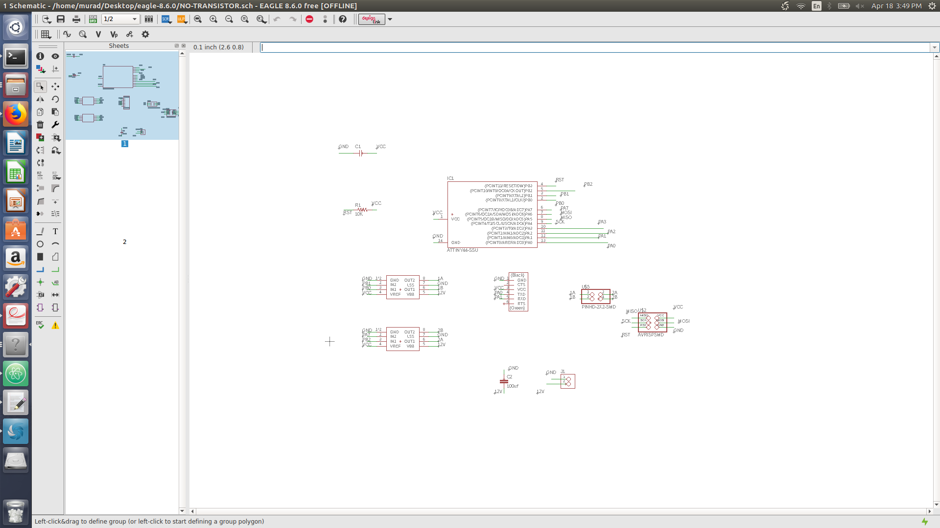
IC motor control
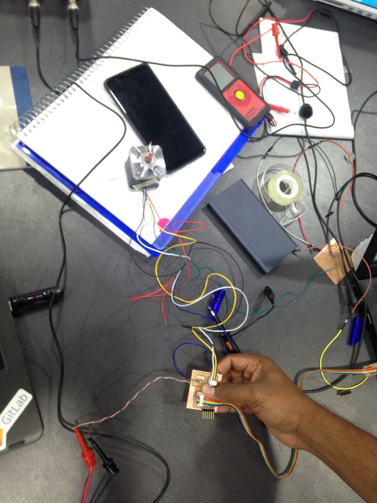
I have used two IC motor controller to control the bipolar motor, One of my IC motor controller was burnt and was withdrawing current.
Code
Bipolar stepper motor has one winding per stator phase, which means it doesnt have a comman lead like unipolar steppers. The Nema 17 stepper motor has two phase thus it contain 4 leads, those lead must be given 5 volts (digital 1) accorddingly in order to drive the motor. I relied on the sequence below to drive my motor.
// Murad Saadeh
// 18/4/2018
// This program is designed to control a stepper motor
#define F_CPU 1000000UL // clock 1MHZ external
#define setbit(register, bit) (register) |= (1 << (bit))
#define clearbit(register, bit) (register) &= ~(1 << (bit))
#define testbit(register, bit) (register) & (1 << (bit))
#include <avr/io.h>
#include <util/delay.h> // include the delay library
#define wait 10
int main (void)
{
int i=0;
setbit (DDRB, PB1); //set PB1 as output
setbit (DDRB, PB0); //set PB0 as output
setbit(DDRA, PA7); //set PA7 as output
setbit(DDRB, PB2); //set PB2 as output
clearbit (PORTB, PB1);
setbit (PORTB, PB0);
clearbit(PORTA, PA7);
setbit(PORTB, PB2);
while(i<200) {
i++;
clearbit (PORTB, PB1);
setbit (PORTB, PB0);
_delay_ms(wait);
//2
setbit(PORTA, PA7);
clearbit(PORTB, PB2);
_delay_ms(wait);
//3
setbit(PORTB, PB1);
clearbit(PORTB, PB0);
_delay_ms(wait);
//4
clearbit(PORTA, PA7);
setbit(PORTB, PB2);
_delay_ms(wait);
}
clearbit (PORTB, PB1);
clearbit (PORTB, PB0);
clearbit(PORTA, PA7);
clearbit(PORTB, PB2);
}
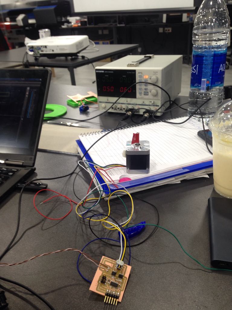
The video below shows how I used the stepper circuit to control my Nema 17 stepper bu using GUI python.
problem faced
- No tranisitor were available so I couldnt complete my h-bridge circuit
- One of my IC motor controller was burnt and was withdrawing current, once I replaced it everything has worked fine
- The bipolar motor uses 5v however the minimum voltage for the IC motor control is 8v, thus I have changed and used a unipolar motor but used it as bipolar motor.