Input devices
As our lab grand opening is very soon, I will add a documenation of an Ultrasonic sensor circuit that I fabricated during my pre fab academy for the final project. I will also add a PIR sensor to my previous designed push-button circuit where I ll use the FTDI connection to do that as it consist of 2 signal pins and a vcc and ground. Moreover I will arduino and breadboard to test other sensor. One of our ideas for the grand opening is to have some sort of digital ribbon, Sibu is actually leading that and explained the need to use a hall effect sensor (magnetic sensor) for that (refer to sibu doc). Thus I ll spend some time researching about the magnetic sensor. Moreover, I ll use a PIR sensor to control my previous push-button circuit, where if the sensor detected movement the LED will turn on. We have a school workshop this week, and I ll be responsible of teaching them how to use ultrasonic sensor with the arduino. Finally I would try to create a capacitive sensor.
Ultrasonic sensor
For my final pre-academy project I made a sensing device for visually impaired people, this device consist of a SR-04 ultrasonic sensor and a buzzer. I will be sharing my input and output device circuit design, and coding here.
- SR-04 Ultrasonic sensor:
- 5v DC input
- Current 15 mA
- Measuring angle: 15 degree
- Accuracy: up to 3 mm
- Measuring distance: between 2 cm and 400 cm
The sr-04 sensor consist of a trigger and echo, where the you only need to supply a short 10uS pulse to the trigger input to start the ranging, an d then the module will send out an 8 cycle burst of ultrasound at 40 kHz and raise its echo. The Echo is a distance object that is pulse width and the range i n proportion .You can calculate the range through the time interval between sending trigger signal and receiving echo signal. Formula: uS / 58 = centimeters or uS / 148 =inch; or: the range = high level time velocity (340M/S) / 2; we suggest to use over 60ms measurement cycle, in order to prevent trigger signal to the echo signal.'’from the date sheet’‘.
In short a trigger would send a signal of 10-15 us, and the echo will be ready to recieve this signal, once this signal is received at the echo the time of this signal is used to get the distance in meters , you ll have to multiply the time of the echo signal by 340 m/s (speed of sound) divided by 2.
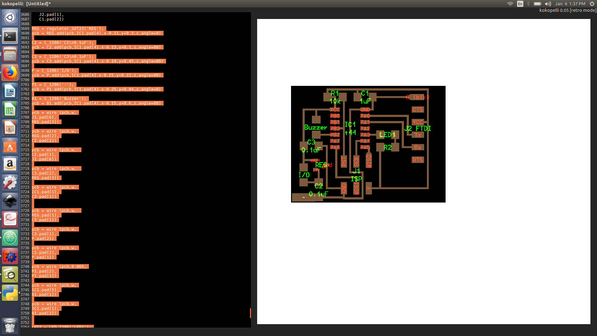
- Kokopelli:
To design this circuit I will be using Kokopelli software. I used AA tiny 44 cad file designed by Neil and I modified it.
- I deleted the XCAL 1
- I added the 5v regulator LM3480 package number SOT 23
- I connected the regulator input and output to 0.1uf capacitor and to ground
- Added Pad by the regulator input for the battery
- Connected the regulator output to the aa tiny 44 Vcc
- Added a buzzer pad between PB3 and Vcc
- Added a LED pad between PA3 and Vcc (connected to 100 ohms resistor)
- Soldering
After soldering I encountered some issue as my programmer wasn’t able to program the board ( Error massage: Check connection), the AA tiny 44 ground pin wasnt soldered properly to the board.
The regulator was releasing smoke as I forgot to add a diode to not block 5 volts from the programmer while programming the board.
The device and the code is working fine when connected the programmer, however when connected to the 9 volts battery the regulator fails to supply 5 volts and only supply the micro-controller with 3 volts.
- Code:
- Set trigger, buzzer and LED as output
- set Echo as input
- set 5 v to trigger for 12us in order to send the signal
- Interrupt echo input pin when changed from low to high
- if echo receives high signal start the counter by setting the pre-scaler to 1
- Else ( if echo receives low signal) stop the counter by setting all the pre-scaler pins to 0
- then start measuring the time in seconds by dividing the TCNT 1 ( where the counter is saved ) by 1,000,000 (clock speed)
- Measure the distance in cm by multiplying the time by 0.034 and dividing it on 2.
- Finally if distance above 200 cm and below 400 cm turn on the buzzer
- The buzzer is turned on by setting the PB2 to zero as its connected to Vcc
Note: I have used register number 1 (16 bit register) TCNT1. Moreover, prescaler 1 has been used as the sr-04 maximuim distance is 4 meter which is 23,200 us = 0.0232 seconds. 16 bit (65536 value) divided by clock speed (1,000,000 hz) would equal to 0.065536 seconds till the counter overflows.
- Constrains
- I mistakenly was reading the echo pin using Port instead of Pin
- I had the Mcros typo errors, I have added an extra bracket after register
// 7th sense product
//
// HC-SR04 sonar sensor and buzzer code
//
// when the distance is above 200 cm and below 400 cm the buzzer will turn on to alert the user
//
// Murad Mousa Saadeh
// 18/12/2017
//
// This work may be reproduced, modified, distributed,
// performed, and displayed for any purpose. Copyright is
// retained and must be preserved. The work is provided
// as is; no warranty is provided, and users accept all
// liability.

#define F_CPU 1000000UL
#include <avr/io.h>
#include <util/delay.h>
#include <avr/interrupt.h>


#define setbit(register,bit) (register |= (1 << bit))
#define clearbit(register,bit) (register &= ~(1 << bit))
#define testbit(register,bit) (register & (1 << bit))


int myTime=0;
int Distance=0;


ISR(PCINT0_vect){

if (testbit(PINA, PA0)){
  TCNT1 = 0;
  TCCR1B |= (0<<CS11);
  TCCR1B |= (1<<CS10); // These 2 register will set the prescaler to 1 and start the counter
 }
else
{
//stop counter and measure time
TCCR1B |= (0<<CS11);
TCCR1B |= (0<<CS10); // These 2 register will set the prescaler to 0 and stop the counter

myTime= TCNT1/1000000; // measure time in seconds
Distance= myTime*340/2; //distance in m

if (TCNT1 < 5000){
  clearbit(PORTA, PA3);// LED on
}
else {
setbit(PORTA, PA3); // LED off
}

}

}


int main(void) {


  setbit(DDRA,PA1);// set trig as output
  clearbit(DDRA,PA0);// set echo input
  setbit(DDRA,PA3); // set LED as output
setbit(PORTA,PA3);//set LED OFF

  sei(); //activate global interrupt
  GIMSK |= (1<<PCIE0); // interrupt in port A, could be done using mcros (GIMSK, PCIE0);
  PCMSK0 |= (1<<PCINT0); // interrupt in pin 0, could be done using mcros (PCMSK0, PCINT0);


   // main loop
   //
   while (1) {
      //
      // trigger pulse
      //

      clearbit(PORTA,PA1);

      setbit(PORTA,PA1);

      _delay_us(12);

      clearbit(PORTA,PA1);

      _delay_ms(1000); // increases time between measures


}
}
PIR sensor
PIR sensor is an infrared digital sensor that detects movement ( it measures the infrared radiations), when movement is detected a digital 1 is sent to the micro-controller. The PIR sensor consist of 3 pins a signal pin, vcc and ground. I have attached the PIR sensor to my push-button circuit FTDI empty pins (check the image below). where I have connected the input signal instead of the Tx (PA0). The code below is that when a motion is detected an LED will lid.
// Murad Saadeh
// 9/4/2018
// This program flashes the LED when a movement is detected by the PIR sensor


#define F_CPU 1000000UL // clock 1MHZ external
#include <avr/io.h>
#include <util/delay.h> // include the delay library

int main (void)
{
DDRA = 0b00001000; //set PA3 as output(LED)


while(1) {
        if (PINA & 0b00000001) // read input pin
        {
          PORTA = 0b00001000; // turn LED off
          }
          else {
            PORTA = 0b00000000; // turn LED on
          }
}
}
I have faced a problem as both my LED and PIR sensor are connecting to Pin A, as when I read input on PA0 to be 1 only, it wont be triggered as sometimes other pins would read 1, thus I have changed it to and (&) insread of (== 1)
Hall effect sensor:
Hall sensor do usually provide either a digital or analog inputs, the sensor which is available at our lab is an analog hall effect sensor. I have checked the data sheet Hall effect sensor data sheet link. The sensor basic working principle is that it supply a voltage proportional to an applied magnetic field. The sensor we are using comes with a linear amplifier to magnify the voltage. When no magnetic field is available the voltage received from the sensor would be 2.5 V ( half the actual voltage), however when the +ve magnetic field ( magnetic south pole) gets closer to the sensor, the voltage received would increase up to 5 volts. Likewise if when the -ve magnetic field ( magnetic north pole) gets close to the sensor the voltage received would be nearly 0 volts.
ADC
To control any analog sensor(such as the hall effect sensor), ADC converter must be used. At the aatiny 44 all pins from PA0 up to PA7 comes with an analog to digital converter. ADC 1 and 0 to an actual number that could be understandable, the aatiny ADC is a 10 bit, thus 5 v represents as 1024 bits.
- At the ADMUX (adc multiplixer register), set REFS0 to 1 to activate the external voltage reference.
- For example If I want to activate the Pin 5 (PA5) to be ADC, set MUX0 and MUX2 to 1
- At the ADCSRA register, enable the ADC converter, by setting ADEN to 1.
- set the pre-scaler to 128 by setting ADDS0,ADDS1, ADDS2 to 1. so that the frequency should be between 50 khz and 200 khz ( ask sibu why ??)
- At ADCSRB to activate th3e external interrupt request, set ADTS1 to 1
- Interrupt vector for the ACD ( vect_adc)
For a better result try to get more than result and have an average of those results ( preferably 100 samples )
Arduino code
#define trigPin 13
#define echoPin 12

void setup() {
  Serial.begin (9600);
  pinMode(trigPin, OUTPUT);
  pinMode(echoPin, INPUT);

}

void loop() {
  long duration, distance;
  digitalWrite(trigPin, LOW);  // clear trig signal
  delayMicroseconds(2); //delay 2 ms
  digitalWrite(trigPin, HIGH); // send the sound wave
  delayMicroseconds(10); // delay of 10 ms
  digitalWrite(trigPin, LOW);// clear trig signal
  duration = pulseIn(echoPin, HIGH); // read input and save it as duration
  distance = (0.34*duration/2); // multiply the distance by 0.34 ( speed of sound in cm) divide the distance by 2 as it going two ways

  Serial.print(distance);
  Serial.println(" cm");
  delay(500);
}
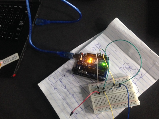
Capacitive senor
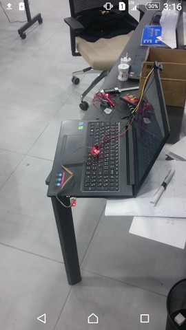
I am really interested in learning how does an actual capacitive senor work. I ll begin by testing it using arduino and breadboard, My instructor Sibu have notified me that there is already a capacitive sensor library in arduino. The capacitiveSensor turns Arduino pins into a capacitive sensor, which can sense the electrical capacitance of the human body. All the sensor setup requires is a medium to high value resistor and a piece of wire and a small (to large) piece of aluminum foil on the end. At its most sensitive, the sensor will start to sense a hand or body away from the sensor. I have used an already available example at arduino for capacitive sensor and then changed it to turn on an led when my hand touch the wires.
#include <CapacitiveSensor.h>

/*
 * CapitiveSense Library Demo Sketch
 * Paul Badger 2008
 * Uses a high value resistor e.g. 10M between send pin and receive pin
 * Resistor effects sensitivity, experiment with values, 50K - 50M. Larger resistor values yield larger sensor values.
 * Receive pin is the sensor pin - try different amounts of foil/metal on this pin
 */


CapacitiveSensor   cs_4_2 = CapacitiveSensor(4,2);        // 10M resistor between pins 4 & 2, pin 2 is sensor pin, add a wire and or foil if desired
CapacitiveSensor   cs_4_6 = CapacitiveSensor(4,6);        // 10M resistor between pins 4 & 6, pin 6 is sensor pin, add a wire and or foil
CapacitiveSensor   cs_4_8 = CapacitiveSensor(4,8);        // 10M resistor between pins 4 & 8, pin 8 is sensor pin, add a wire and or foil

void setup()
{
  pinMode ( 5, OUTPUT);
   cs_4_2.set_CS_AutocaL_Millis(0xFFFFFFFF);     // turn off autocalibrate on channel 1 - just as an example
   Serial.begin(9600);
}

void loop()
{
    long start = millis();
    long total1 =  cs_4_2.capacitiveSensor(30);
    long total2 =  cs_4_6.capacitiveSensor(30);
    long total3 =  cs_4_8.capacitiveSensor(30);

    Serial.print(millis() - start);        // check on performance in milliseconds
    Serial.print("\t");                    // tab character for debug windown spacing

    Serial.print(total1);                  // print sensor output 1
    Serial.print("\t");
    Serial.print(total2);                  // print sensor output 2
    Serial.print("\t");
    Serial.println(total3);                // print sensor output 3

    delay(10);                             // arbitrary delay to limit data to serial port

    if (total1 > 30) {

      digitalWrite( 5, HIGH);

    }
    else {
      digitalWrite( 5, LOW);
    }
}
 problem faced is that I was using 330 ohms resistor, and to relieve reading, I would near a higher resistor.