In this week's asignment, I am learning to use eagle to design my own circuts and pcb boards.
Eagle is a productive tool, which allows you to draw a sketch of your board with an abundant library of elements, to generate the image of the board accroding to your sketch, and output it as gerber files, which can be recognized by gcode generaters like CopperCam.
This week I am trying to imitate Neil's hello board, designing and finally produce it.
DRAW A SCHEMATIC WITH EAGLE
Before darwing a schematic, we have to check our library. Eagle is installed already with librarys, but now we have to download basic libraries of Sparkfun in the library manager. Then, for some special designed elements like ATtiny chips and ICSP bus solder pads, which are not included in Sparksfun Libraries, we have to download a fab.lbr from git hub in order to complete our design tasks for fabacademy.
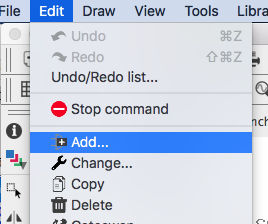
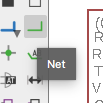
Add new components for the sketch.

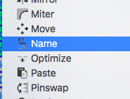
There are two ways to connect the components together. First, you can draw actual nets between the pins of the components. Second, you can use labels to connect two pins that are two far from each other in your sketch; pins with same label names will automatically connect together.
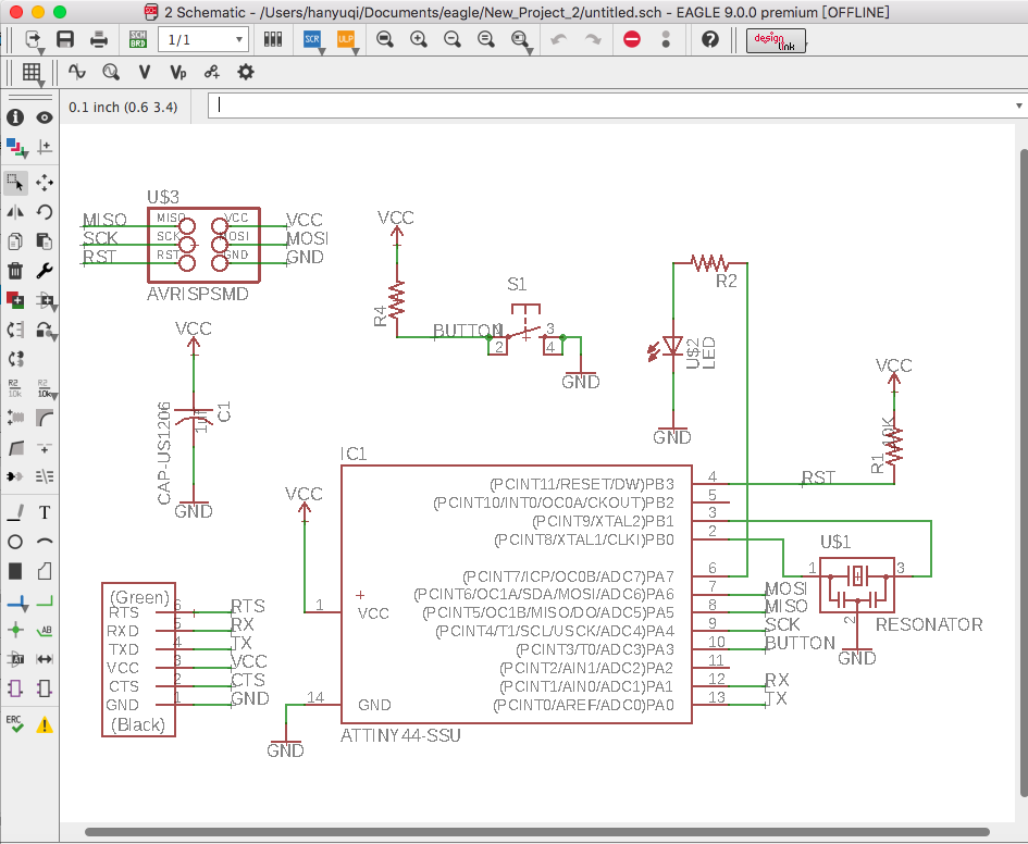
Design the "Board"
In the BRD window, we can see what the pads and routes on the board will look like; we can also design the board ourself by changing the positions and directions of components or route the board.
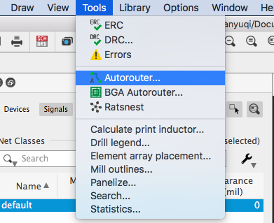
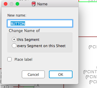
We can use both manual routing or a autorouter.
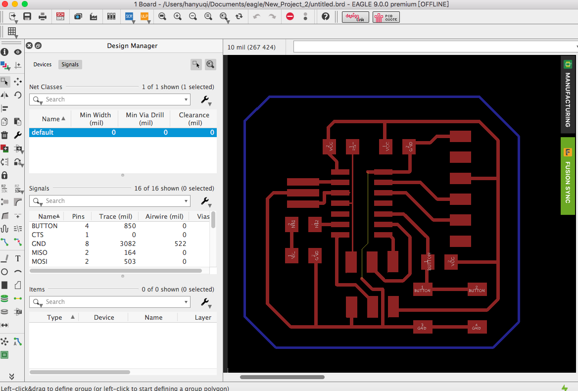
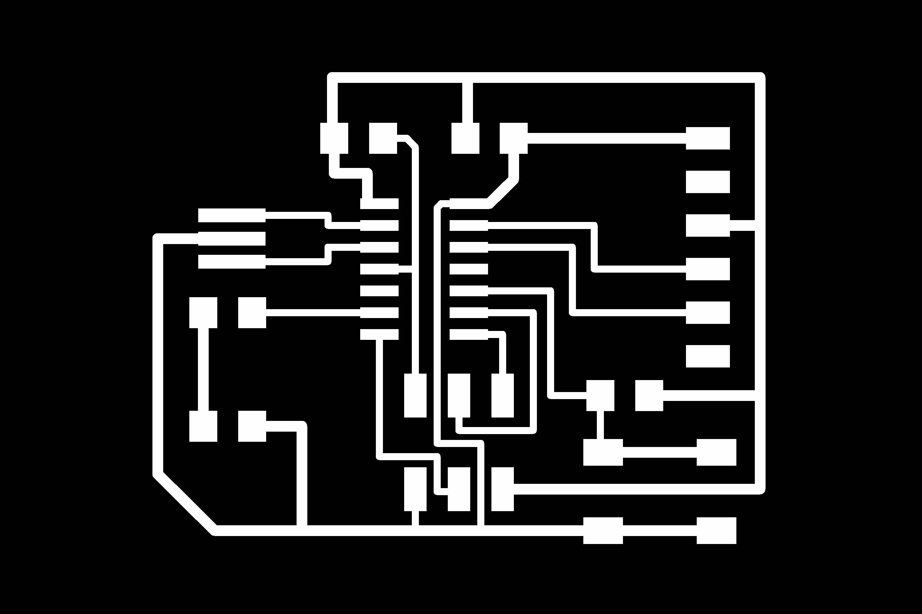
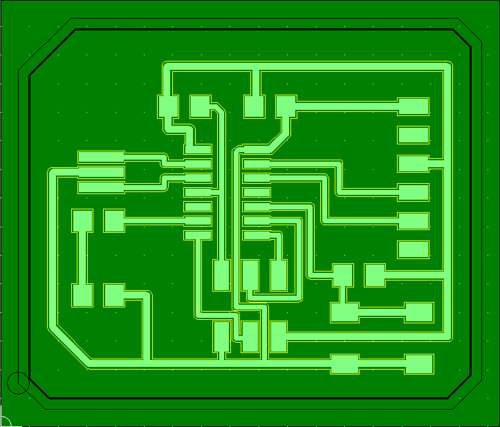
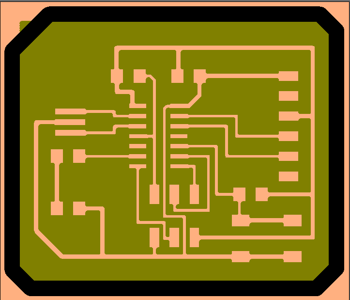
This is what the board will look like. Save it.
Applying design rules––Check the schematic and the board
We did design the circuit and the arrangement of the parts. However, to guarantee that our circuit is correct, we have to use design rules to check our schematic and board. Here are some simple rules to statr with:
First, connect the pins of elements that has the same name. Like to connect the ISP port and the microcontroller, I have to connect RST to RST, SCK to SCK, etc.
Second, provide some protection to your circuit. In other words, always be careful about the VCC input voltage and the ground. We usually chain a 10k resistor between the VCC pin of microcontroller and the voltage supply to protect the mircrocontroller from being hurt by high voltage. Also, to help reduce the fluctuation of the voltage, we can add a 10uf capacitor between VCC supply and GND supply––regulating is one of the functions of capacitors.
Third, when routing the board, be careful with the space between traces and pads––if you only have a 0.4mm tool, then the space should be more than 0.4mm wide, or your CAM software cannot generate a route that could cut this gap out.
To check whether our board is correct, we can use two tools on EAGLE: ERC and DRC.
ERC & DRC
Eagle provides two tools that help you to check whether your board is correct or not:
a.) Electrical Rule Check (ERC)
The ERC checks e.g. for any open or overlapping pins and ports on your schematic and will give out these errors.
b.) Design Rule Check (DRC)
The DRC establishes a set of boundaries for trace widths, component spacing, via diameters that you can check for your board.
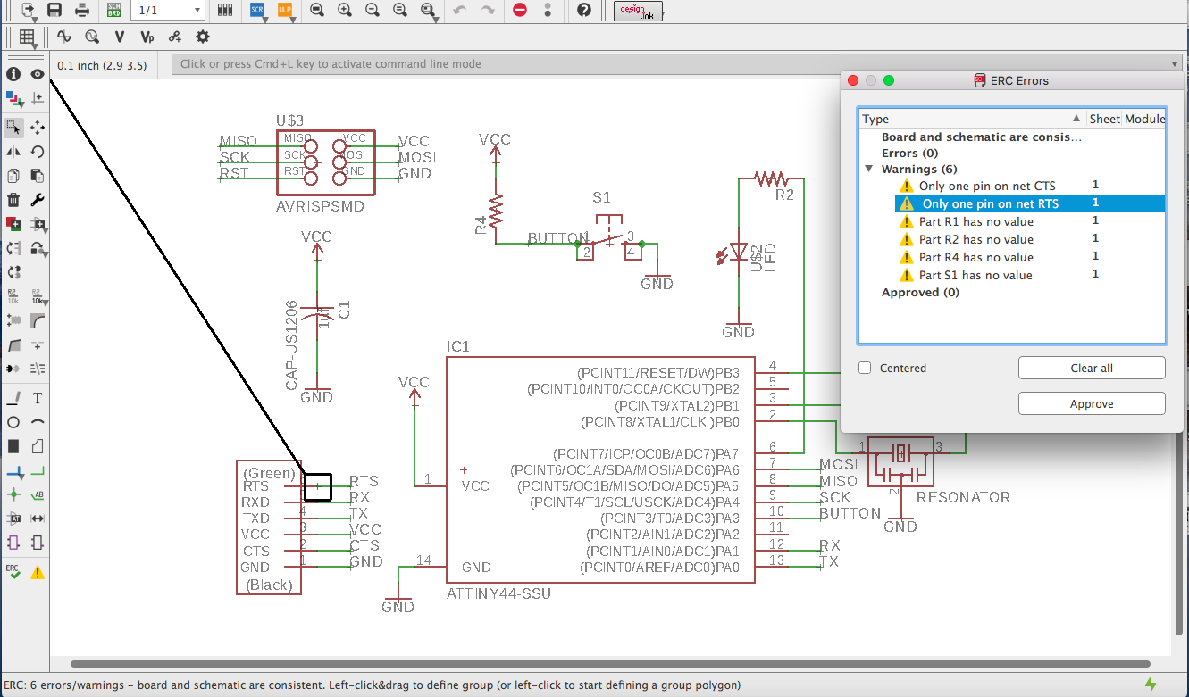
I launched ERC and it says I made some mistakes: I hadn't add values to some of the resistors that ERC cannot check the curcuit.
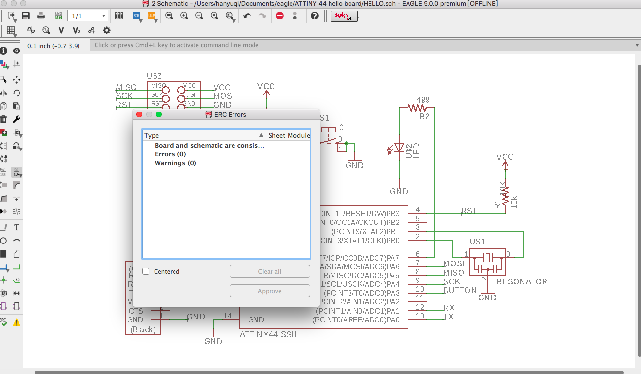
Then I added value to those resistors and deleted the single pins on CTS and RTS. ERC says there is not error now.
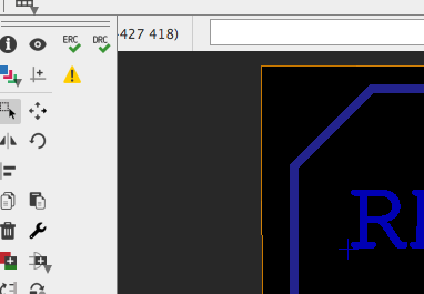
Now go to the BRD view and find the DRC tool.
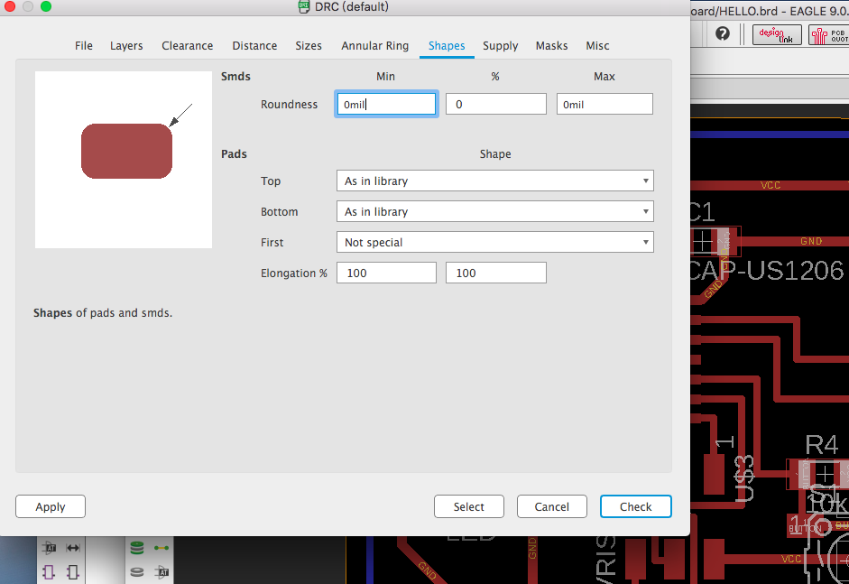
This is the window of DRC. We can change the layers, shapes of pads, other signs, etc, in this page. After confirming the design rules, click "Check".
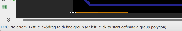
Now we do not have any problems on our design rules, because we can see on the bottom that DRC reports no errors.
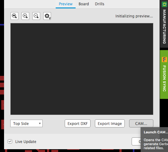
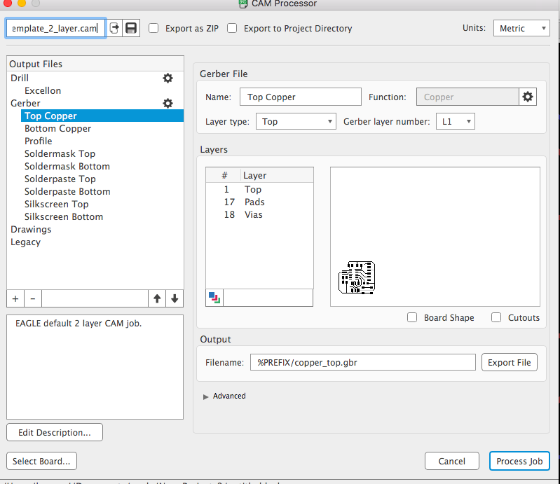
Manufacture and create gerber files
Click on MANUFACTURING and then click CAM. Select the layers you want to produce and output a gerber file, which can be used later to generate gcodes, the route of CNC machines.
Generate Gcode with CopperCam and Mill the board
Because my milling machine, which is controlled by mach 3, cannot recognize the gcode produced by the fab module online generator accroding to the fab isp image on the class schedule, I decide to continue my making of the hello board from the electronic design week.
Now we are loading our gerber file on the CopperCam to generate route and gcode.
CopperCam
CopperCam is a windows-based tool, so I have to use another computer to install CopperCam.
< Here to visit CopperCam website >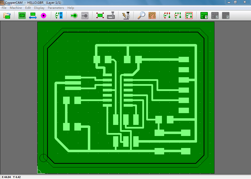
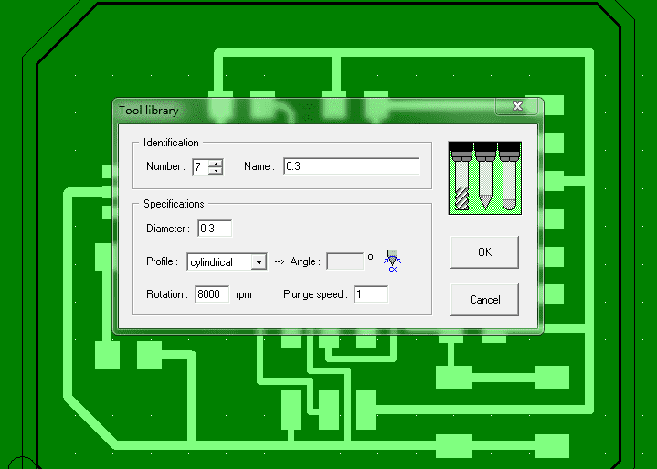
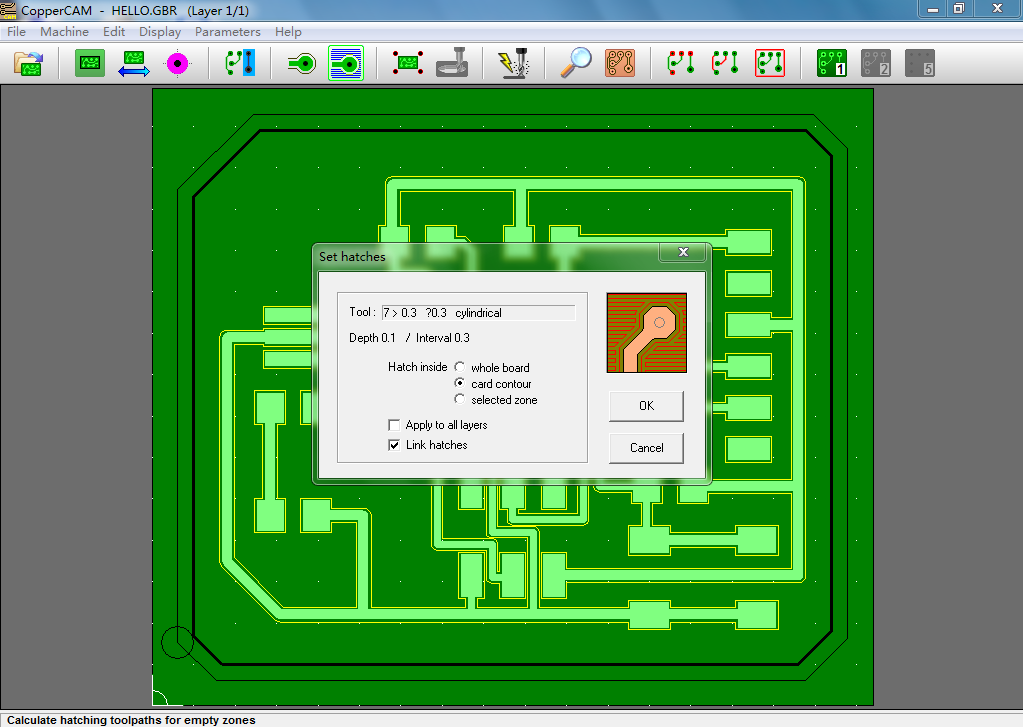
CHOOSE YOUR TOOL
After installing, we have to go to too library to add our own tools. I am using a 0.3 mm tool.
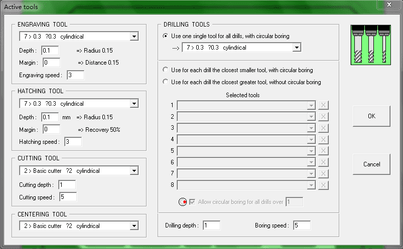
Then let's select our added tool for different process: isolation, hatching, and boundary.
CALCULATE THE ROUTE
First let's click isolation. CopperCam will generate route and visualize it.
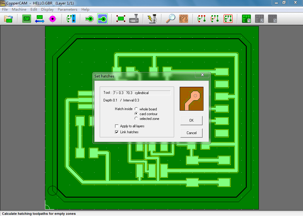
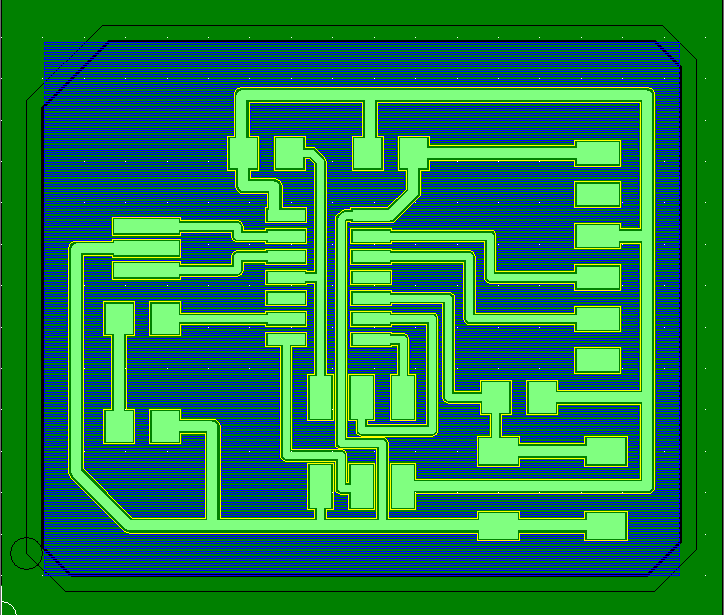
Now it turns to hatching
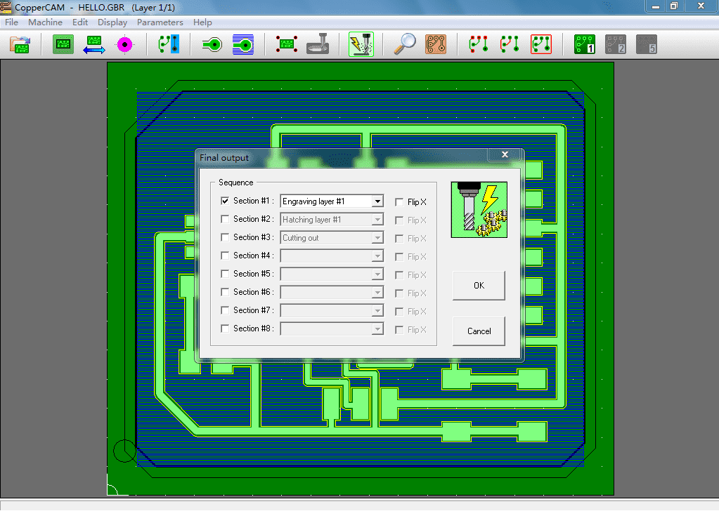
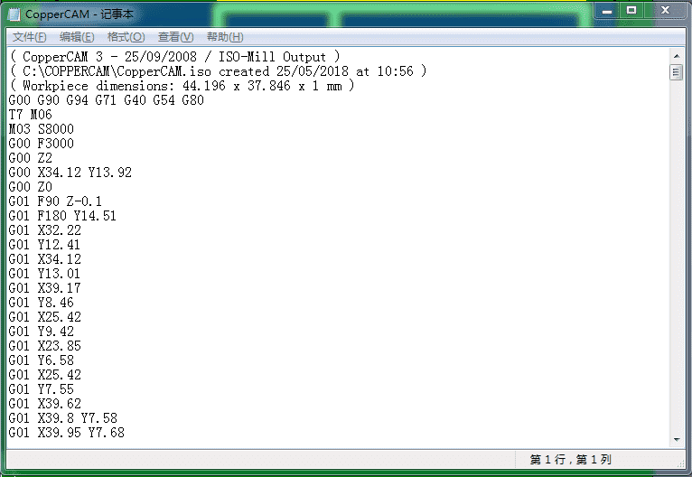
GENERATE GCODE
All the cauculations are done. Click the Mill button (which has a drill and lightning) to generate gcode. Remember to change the file name because the default one will lead you to save an iso file, which cannot be read.
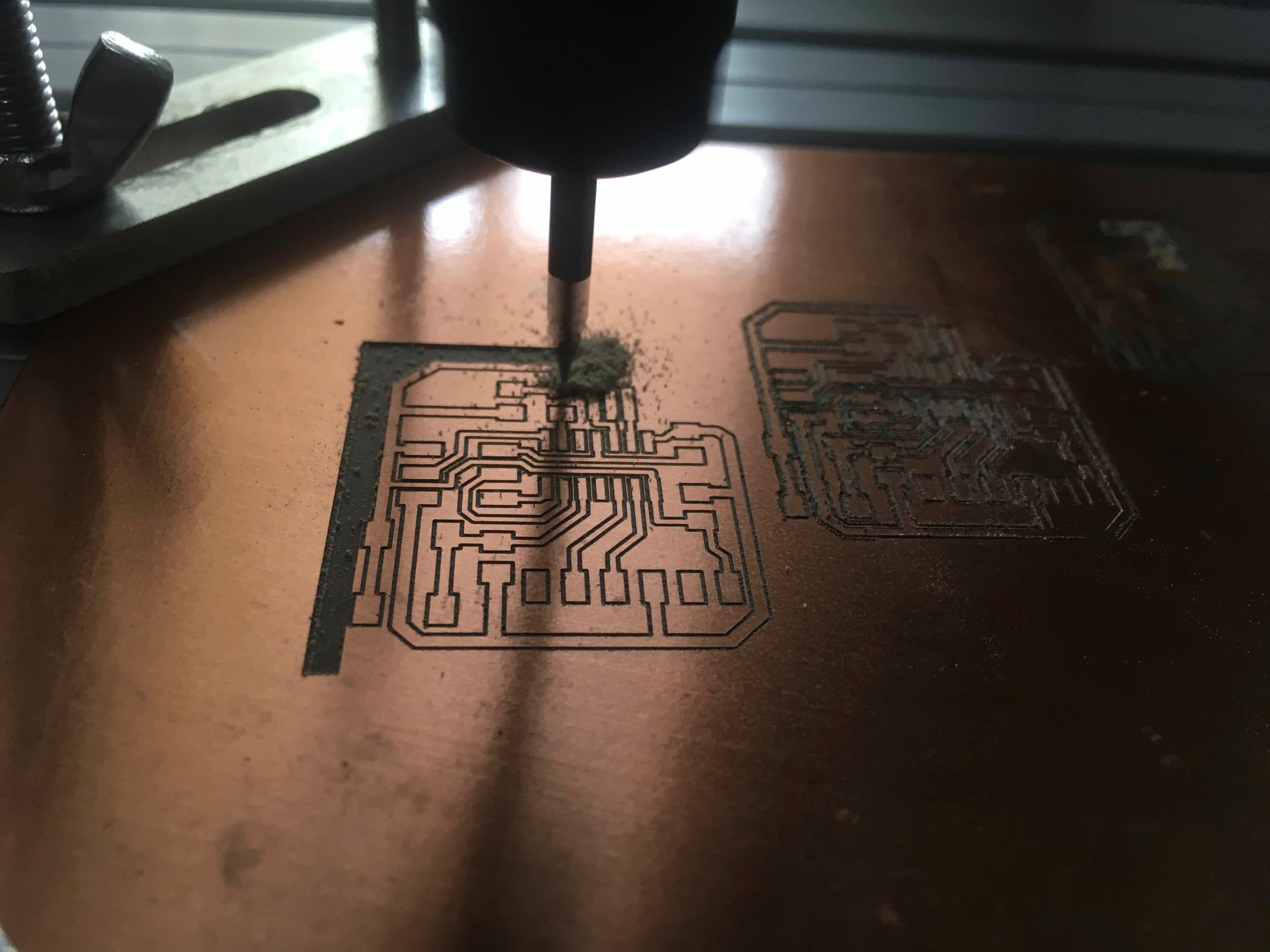
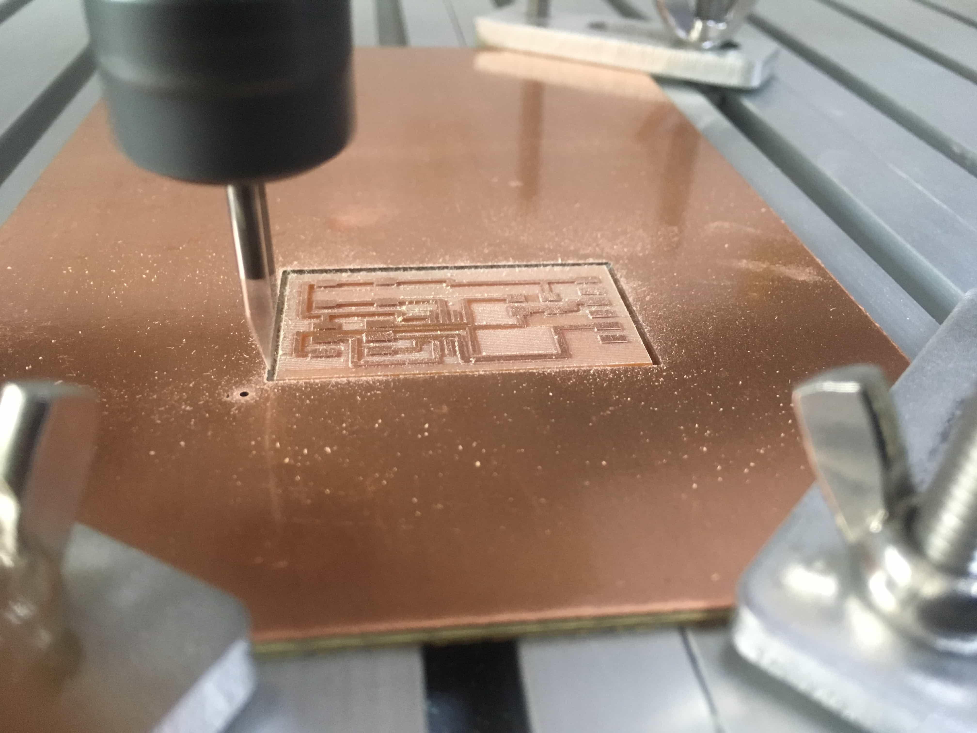
MILL THE BOARD AND SOLDER COMPONENTS
Now, copy the gcode to Mach 3 and start milling. Be careful that the board must lay very very flat and should be fixed on the platform, or it will vibrate when milling so that the route will not be cut out accurately.
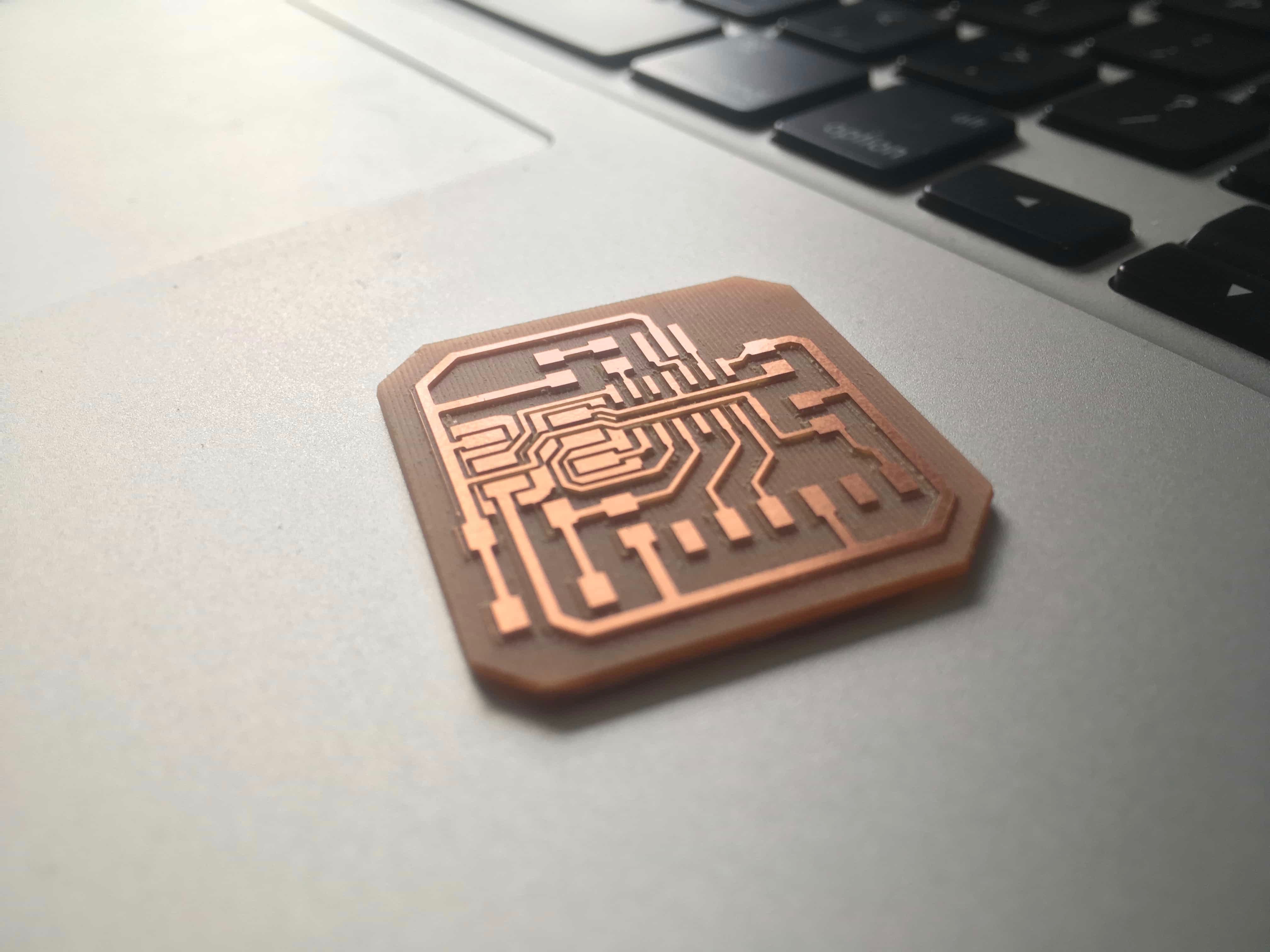
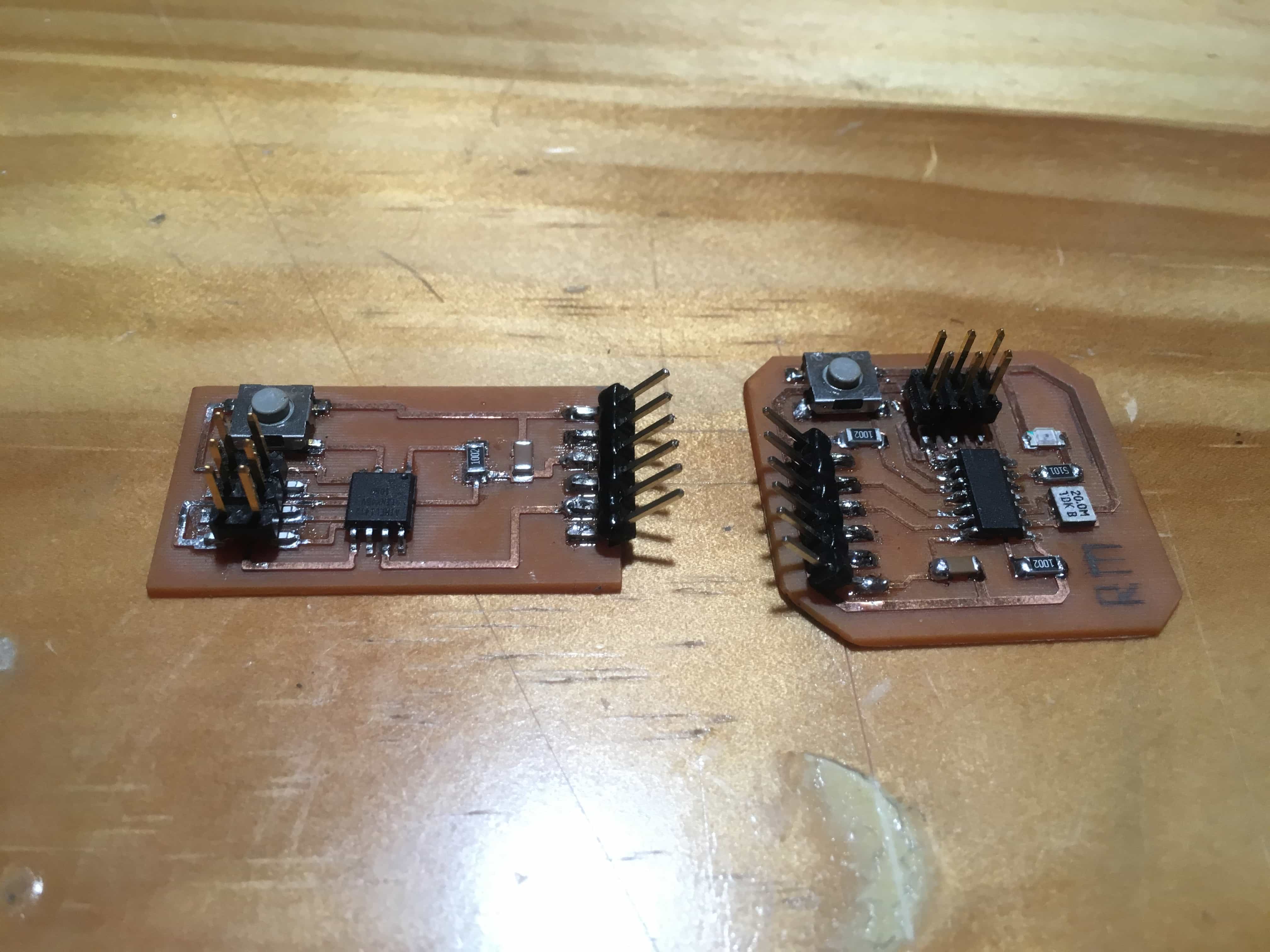
For soldering, I have a suggestion: it is easier to smear tinol (a paste like soldering tin, often used to solder chips that has large number of pins) on the pins and soldering pads, and then use soldering iron or blowing heater to solder the parts.

This work is licensed under a Creative Commons Attribution-NonCommercial 4.0 International License.