This week I am required to mill the Fab ISP and make it work.
Now we are loading our gerber file on the Fab Module to generate route and gcode.
Fab Modules
Fab module is an online platform with can transfer your design files to the routes of cnc machines.
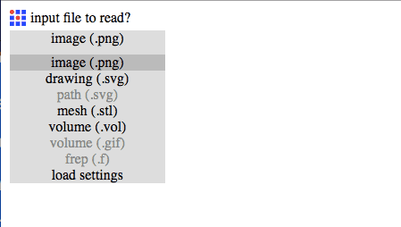
First, upload the png image of Fab ISP to fab modules.
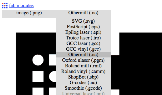
Second, choose the output format. Because I am using a milling machine build previously by some college students, I had to choose "other mills".
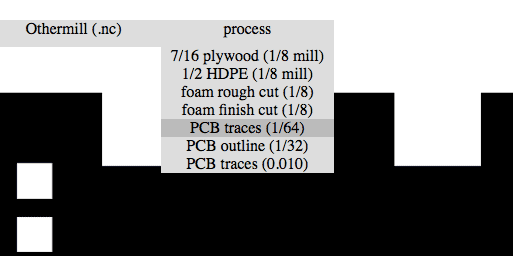
Third, choose the process of milling. Since we are milling PCB traces and using a 0.4mm tool, choose PCB traces 1/64.
In the end, click "calculate" to calculate the route of cnc machine. After the calculation finished, click "save" to generate gcode.

CHOOSE YOUR TOOL AND PCB BOARD
TOOLS
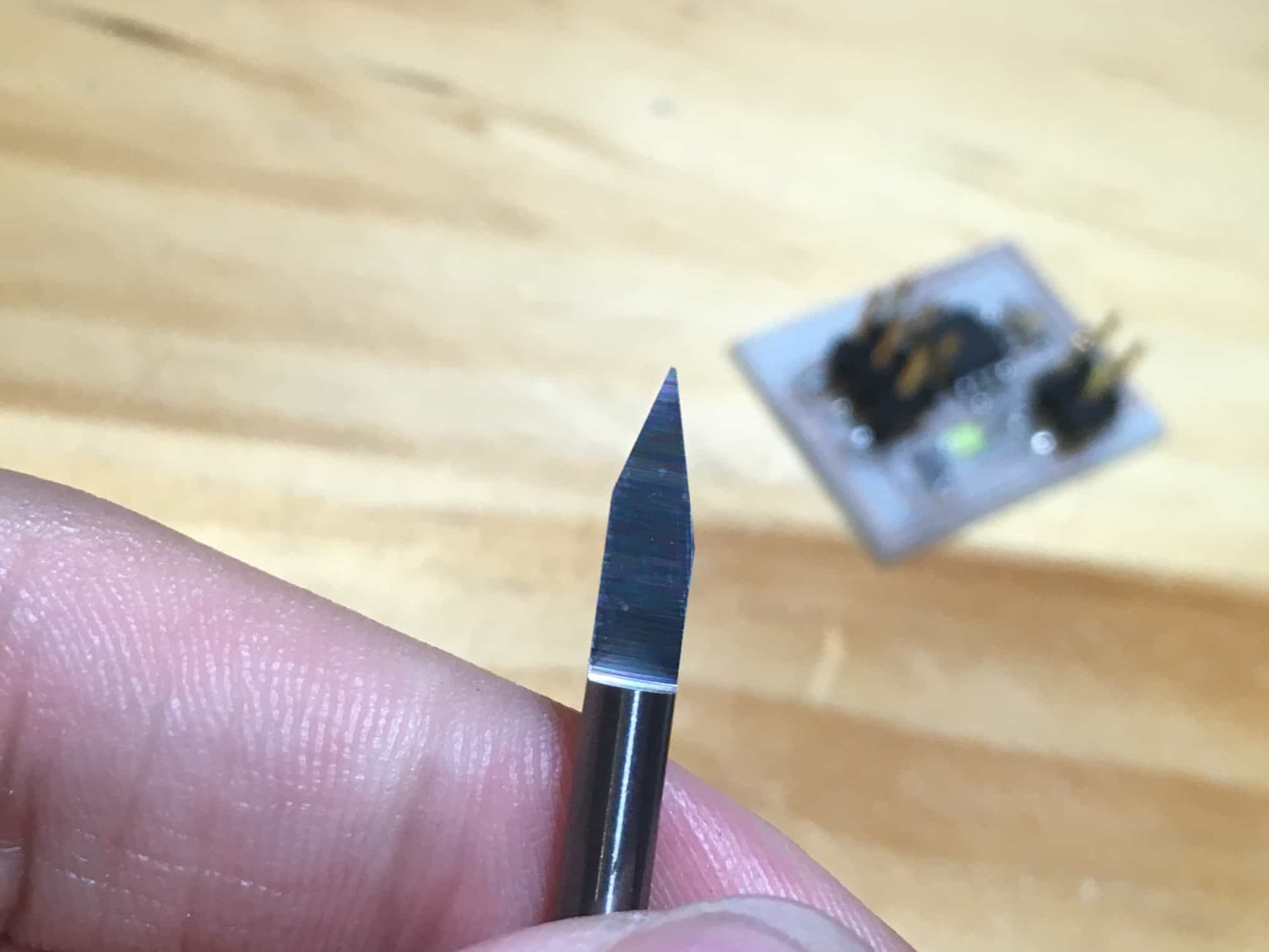
Choosing conical tools can reduce the chance of breaking your tool and improve the speed, since you won't worry whether the tool would break because of high cutting speed. However, this is not very accurate in cutting –– a 0.4 mm conical tool would cut thicker trace in a depth of 0.1 mm because of the angle. So in order to cut a 0.4mm trace and minimize the error, I was using a 0.3 mm conical tool with an angle of 20 degrees, which most approxmates 0.4 mm at 0.1mm depth.
In fact, if you are not in a hurry, using a 0.4 mm cylindrical tool seems more professional. But you have to set the feed rate lower in order to prevent the tool from breaking.
PCB BOARD
PCB boards can be classified as FR1, FR2, FR3, FR4, etc, according to different materials. FR1, FR2, and FR3 are paper-based–––which means that they are made from the mixture of paper and epoxy. This is very cheap with low density, but is not very good in heat resistance and strength. The most common one is FR1. FR4 and some of FR3 are made from a mixture of different layers of epoxy, paper, and fiber glass, which provides better performance in temperature endurance, insulation, and strength. However, this is much more expensive and hard to drill because of higher density. People often use FR3 and FR4 to make double-sided computer mainboard.
For me, I only had FR1 board. In fact, FR1 is enough to make single side board like Fab ISP. And is much cheaper so that I would not worry about the cost when I am testing the machine with a PCB.
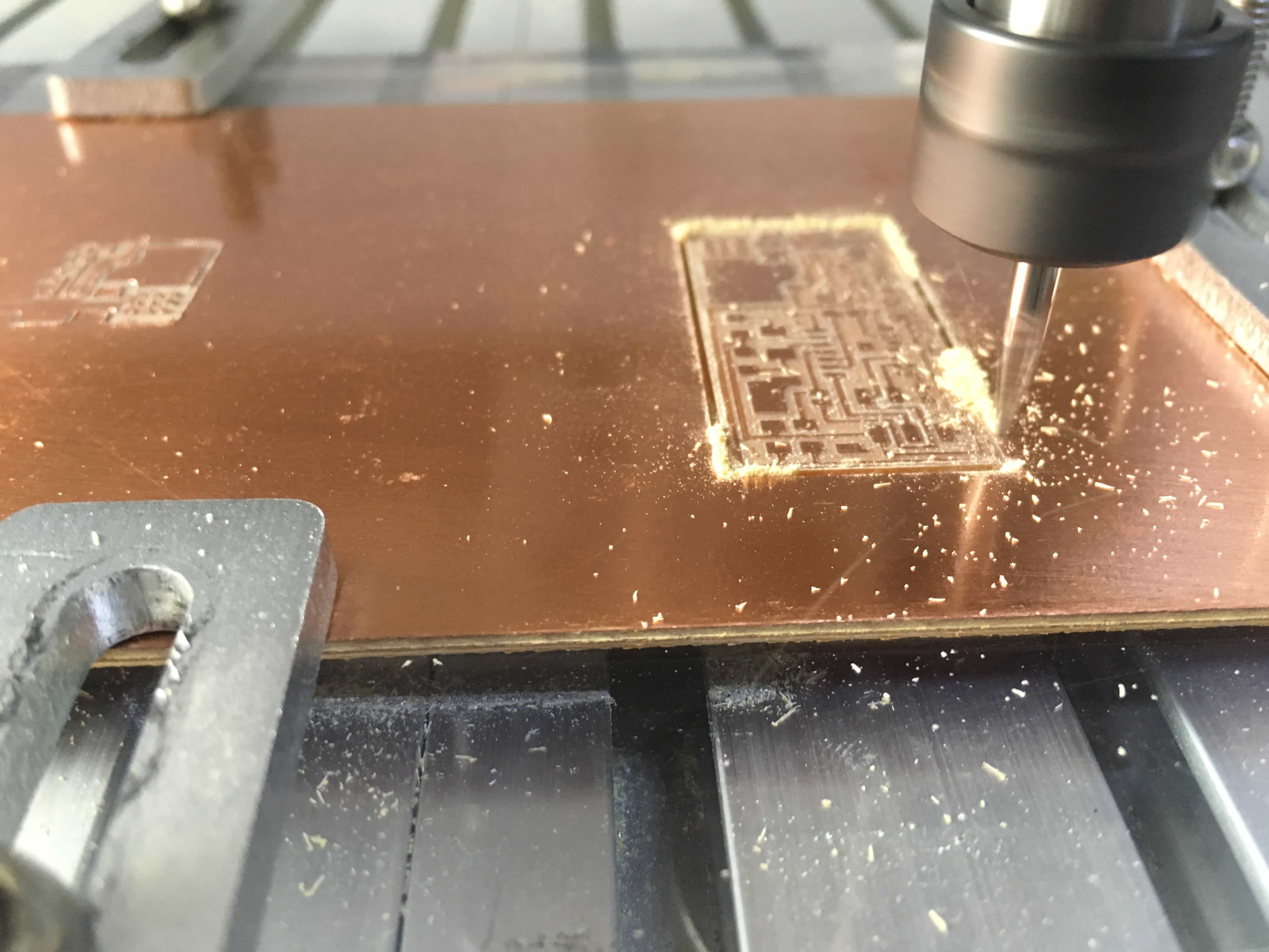
MILL THE BOARD AND SOLDER COMPONENTS
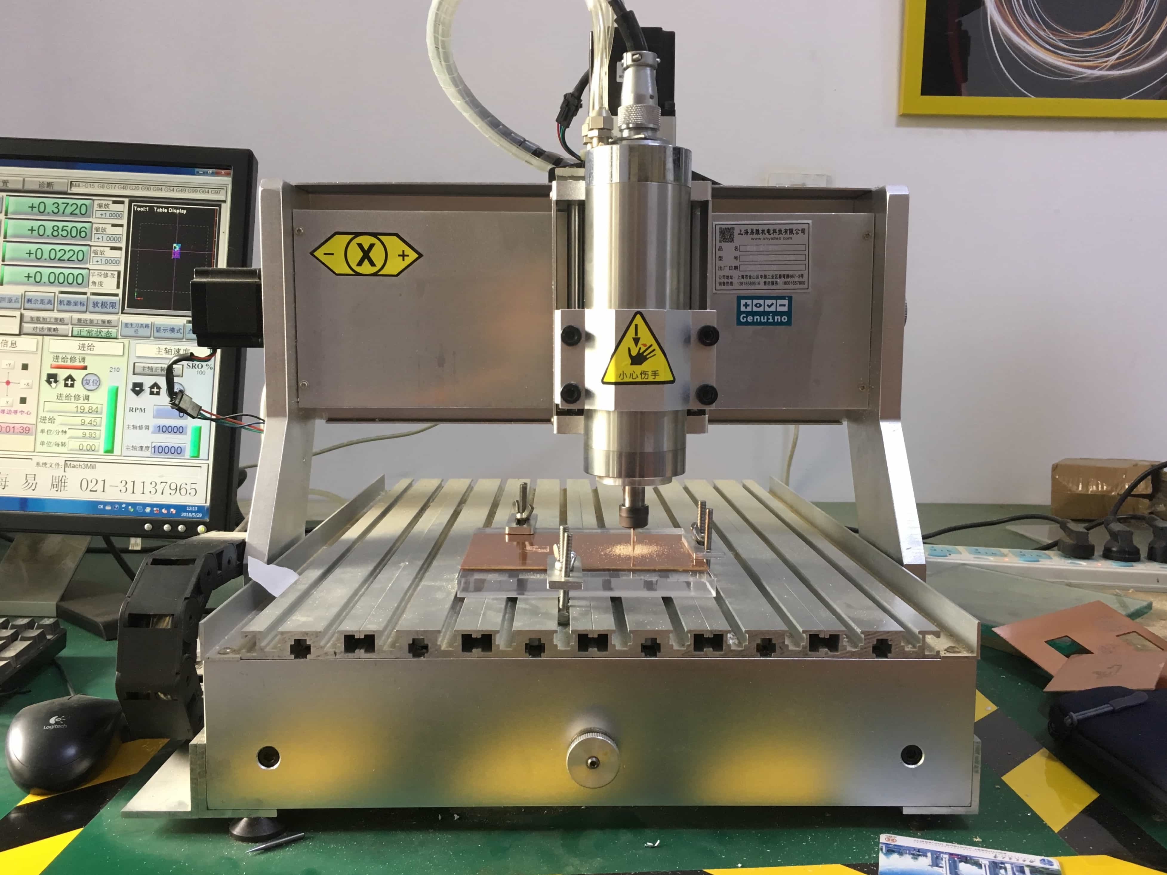
Now, copy the gcode to Mach 3 and start milling. Be careful that the board must lay very very flat and should be fixed on the platform, or it will vibrate when milling so that the route will not be cut out accurately.
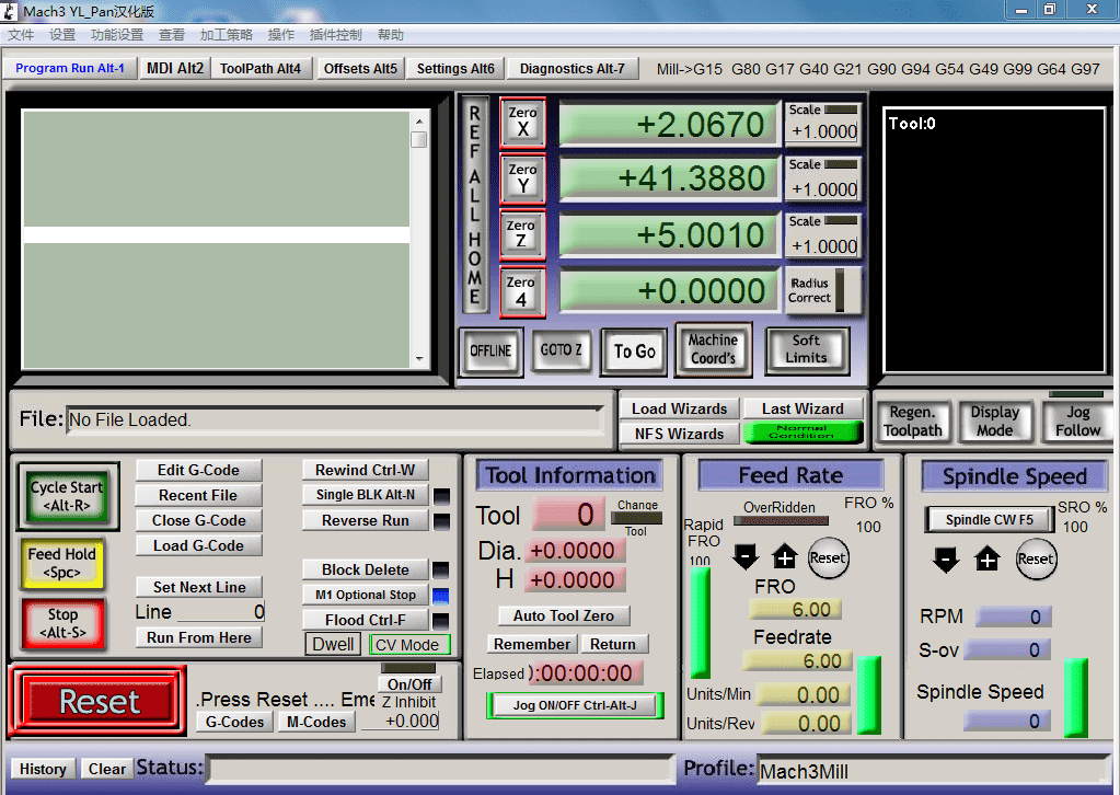
The user interface of Mach3.
Click "files>load the gcode"to add the gcode in txt files or nc files. Then the code would be displayed in the white rectangular area, while in the black rectangular area you will see the virtual route generated with the code.
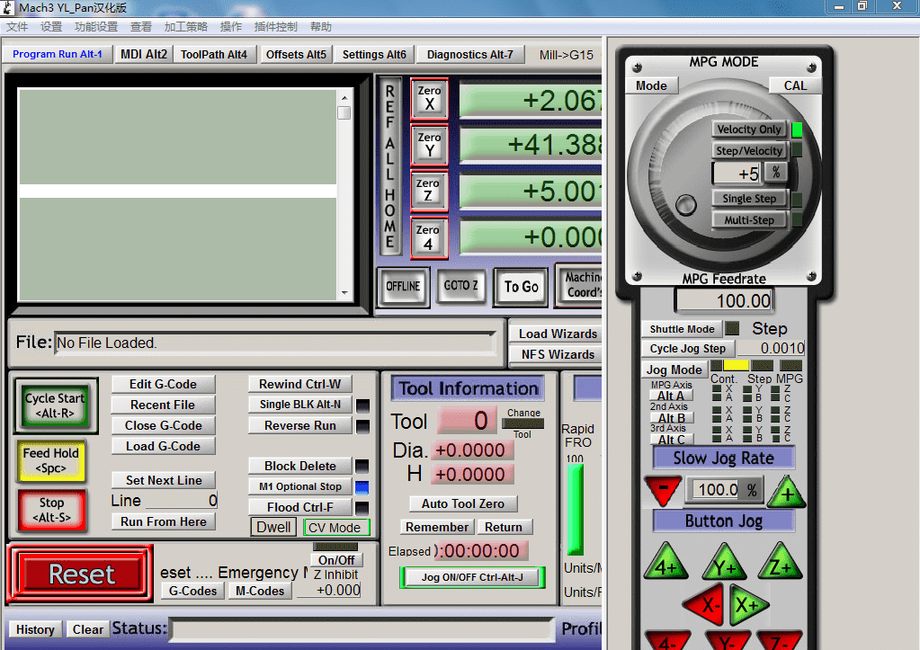
Press TAB and you can see a control pannel on the right, in which you can manually adjust the position of the drill by clicking the XYZ buttons.
Back to the main window, you can change the feed rate at "Feed rate" area from 0 to 200% output.
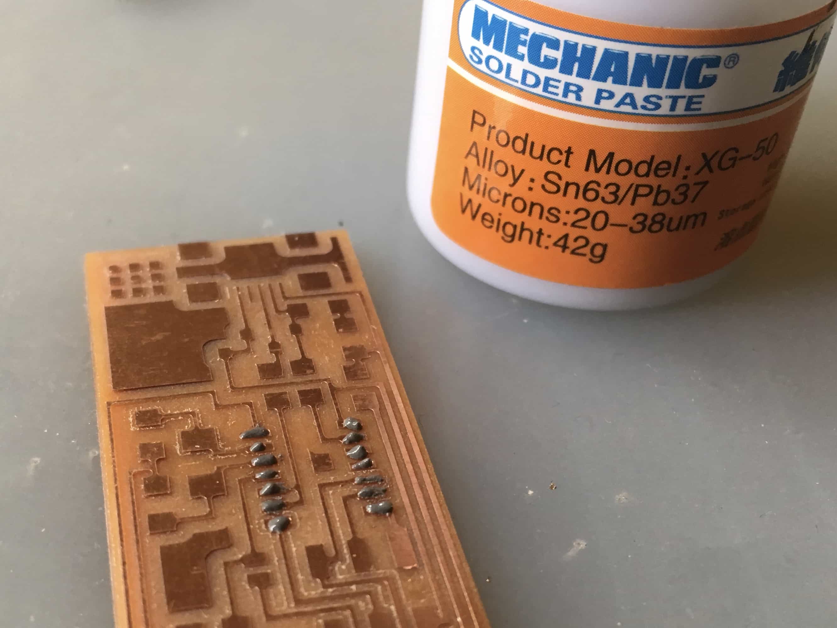
For soldering, I have a suggestion: it is easier to smear tinol (a paste like soldering tin, often used to solder chips that has large number of pins) on the pins and soldering pads, and then use soldering iron or blowing heater to solder the parts.
 <
<
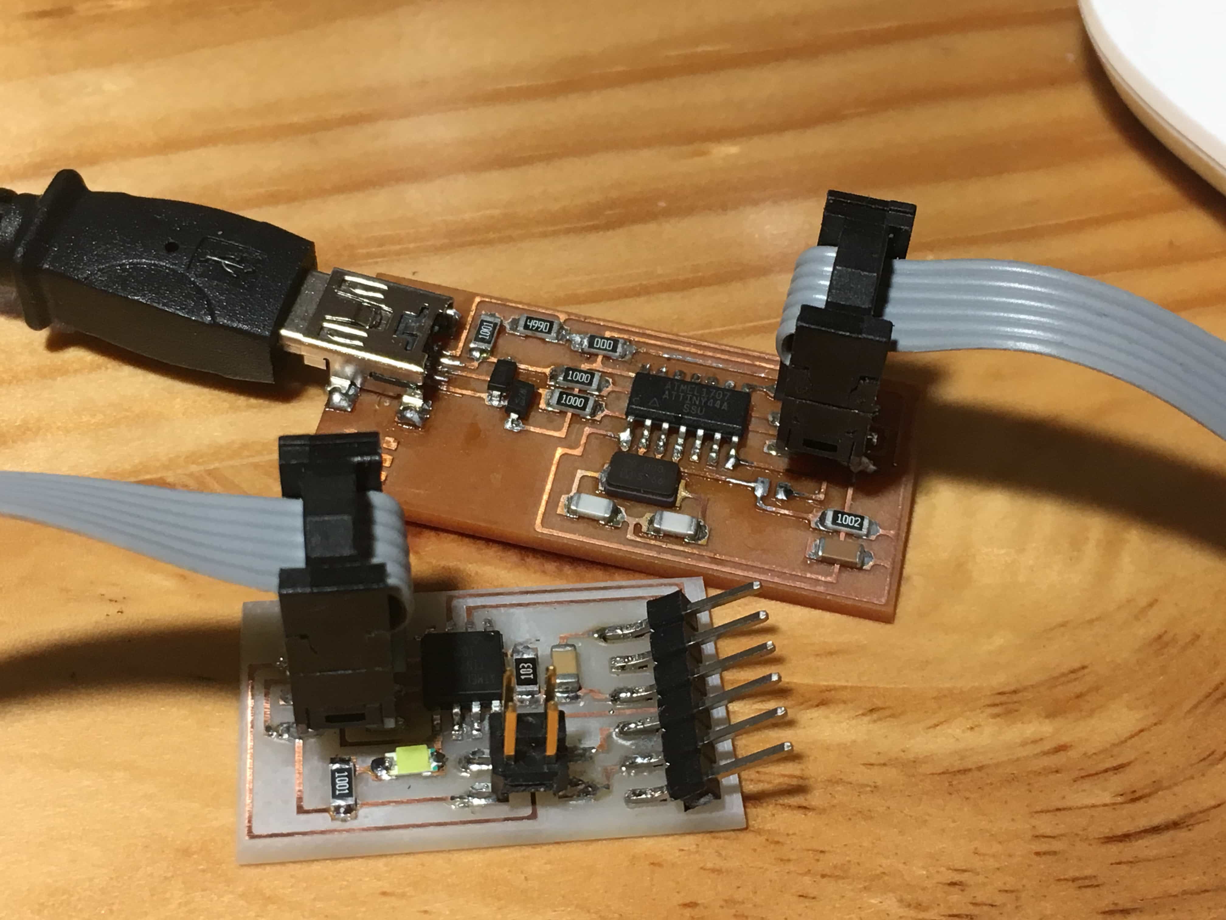
PROGRAMMING THE FAB ISP
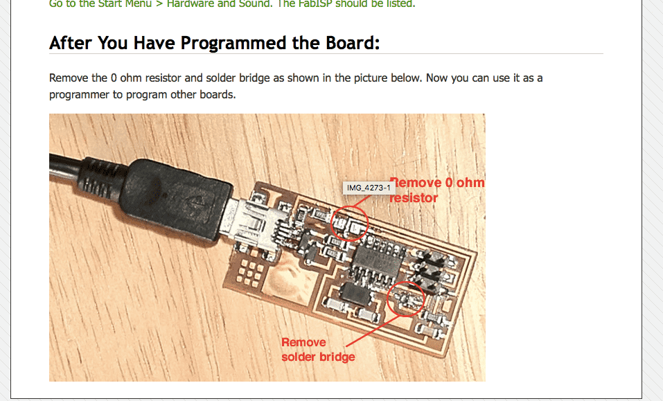
Folloing the instruction in the schedule, I downloaded the firmware and programed the ISP with another usbtiny ISP. In the instruction, it is said that we have to remove the solder bridge and the 0 ohm resistor after we program the board so that the computer could recognize the Fab ISP and then you can really make use of it. However, I found that there is a mistake: the 0 ohm resistor should not be removed because it connects the GND of usb port and the GND of ICSP port. If it is removed, the board connected to your Fab ISP cannot reach a GND so your programming will fail.
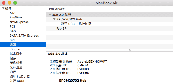
And if you successfully made your board, when you connect Fab ISP to the usb, your computer would display "Fab ISP" on usb devices.
PROBLEMS AND FIXES
1. When I tried to generate gcode on fab modules, I did not make it the first time when I load the code to machine because I did not choose the right machine. At that time, I should had known that .nc is a format of gcode, and if the machine only recognizes .txt, just change the name of the file to .txt.
2. As I said, I found that we should not remove the 0 ohm resistor after programming.
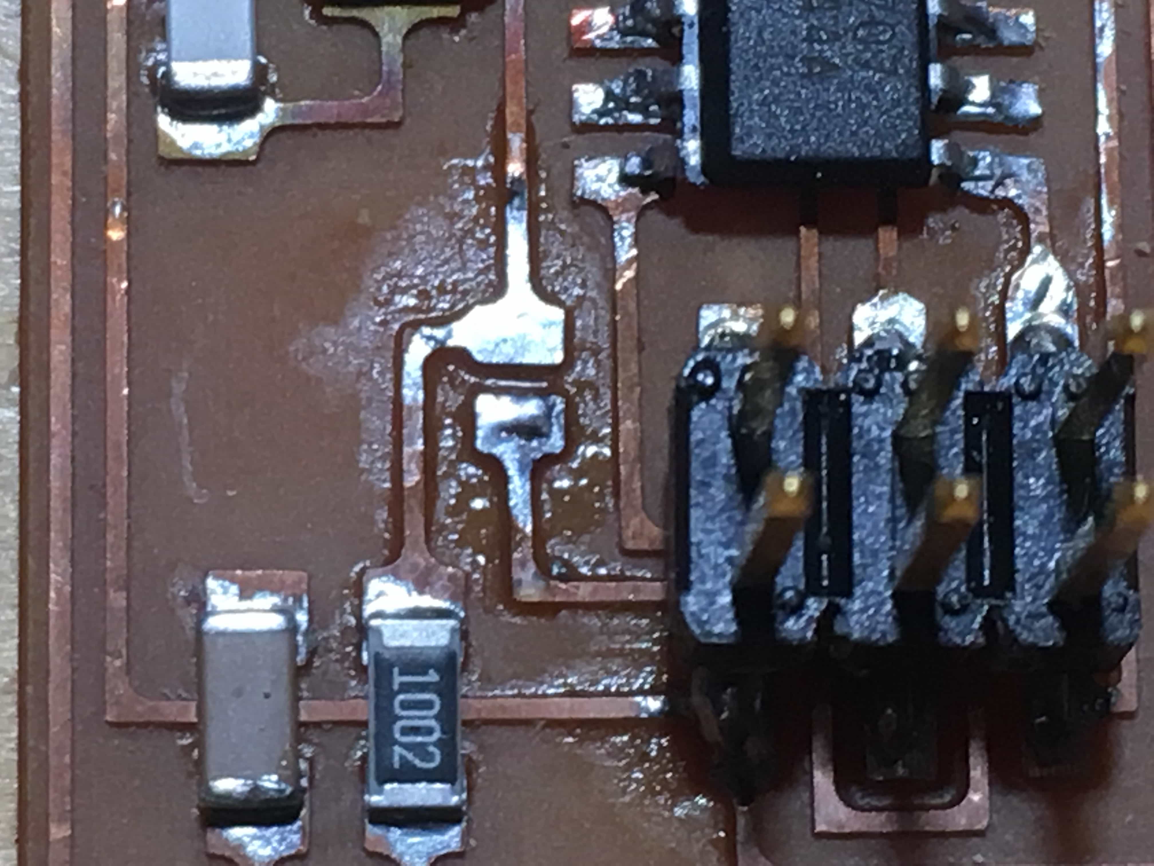
3. At first my computer did not recognize my Fab ISP. The reason was that the usb port on the board was not perfectly soldered––they are too delicated and often cause mistakes. So check the circuit after you solder the parts.
