Output devices are some devices that could transform the digital signal into other forms of information, motion, or other functions.
This time I am making an RGB board and make some code to display different colors of light.
READING THE DATASHEET
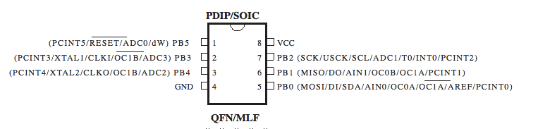
I am using ATtiny 45 as the microcontroller. And the first thing to do is to read the data sheet and decide what pins I am using. Since the RGB diode shares one VCC, the three negatives controls three colors: red, green, and blue. After reading that, I decide to connect the pins like this:
PB2––– Blue
PB1––– Red
PB0––– Green
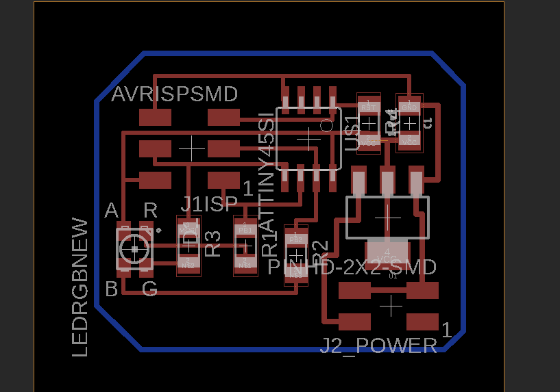
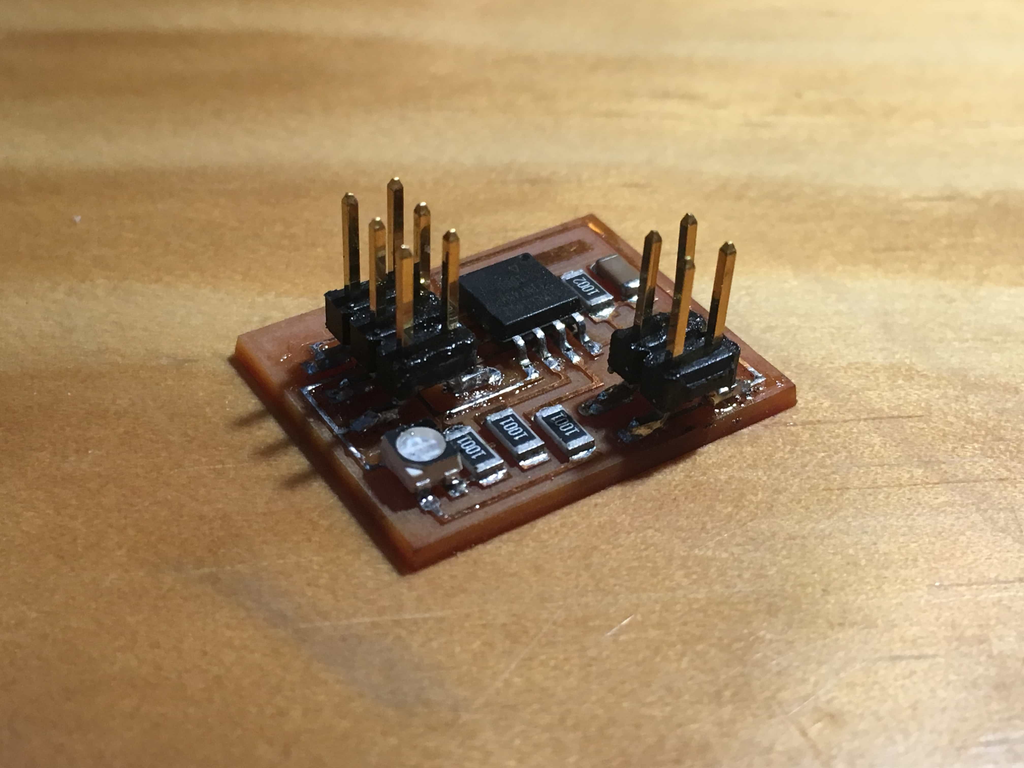
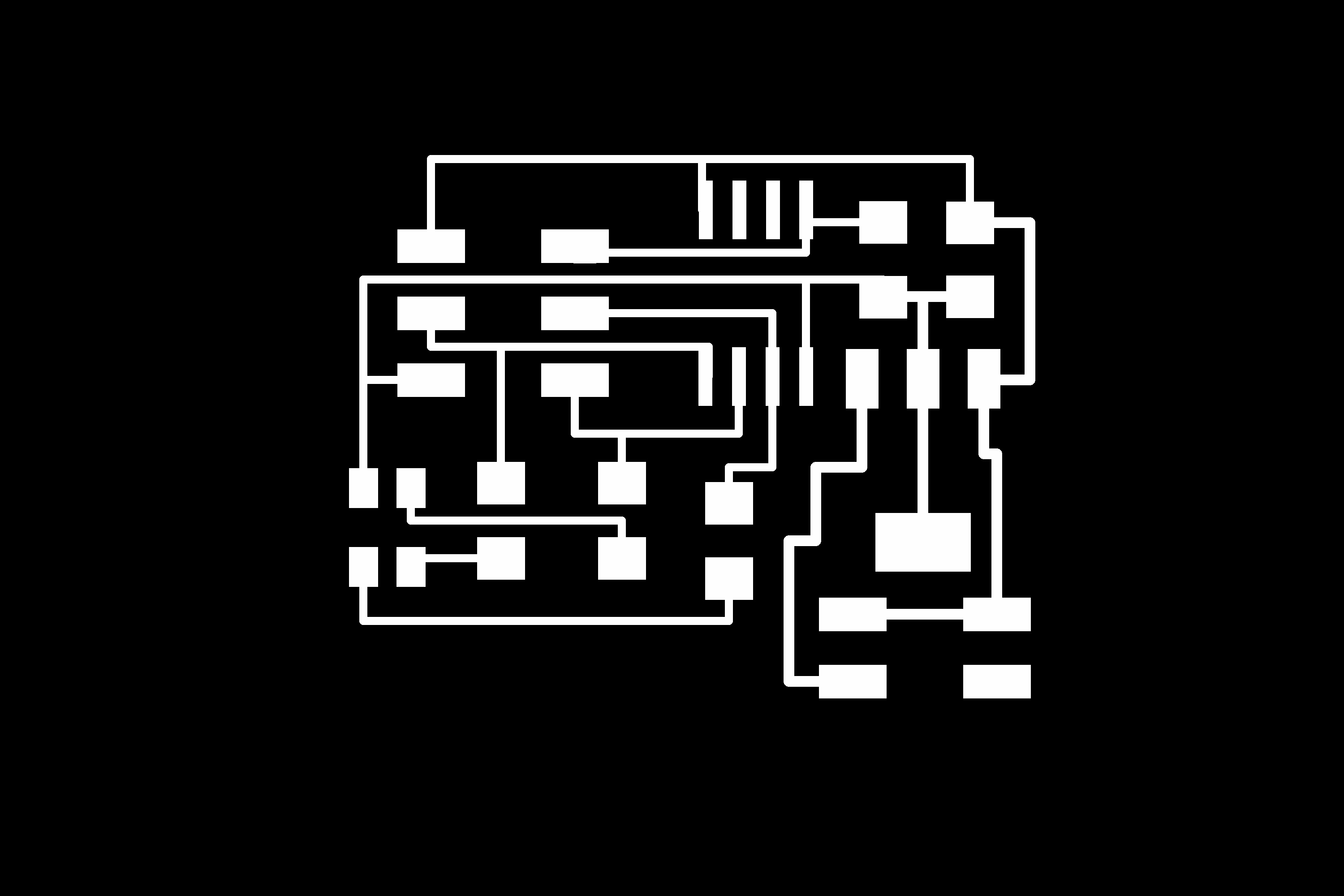
DESIGNING AND MAKING THE BOARD
I designed the RGB board and changed the regulator to a AMS1117 (SOT223), which can hold 5V-1A. Because my power is from the computer USB dock, which is also 5V-1A.
PNG file: RGB-traces RGB-interior
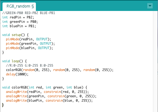
PROGRAMMING THE BOARD
After that, I used Arduino IDE and my Fab ISP to program the board.
Since this is a RGB diode that three colors have the shared VCC, the brightness of each color increases from 255 to 0 (This is because when pin is 255, the voltage between the diode is zero, and vice versa.
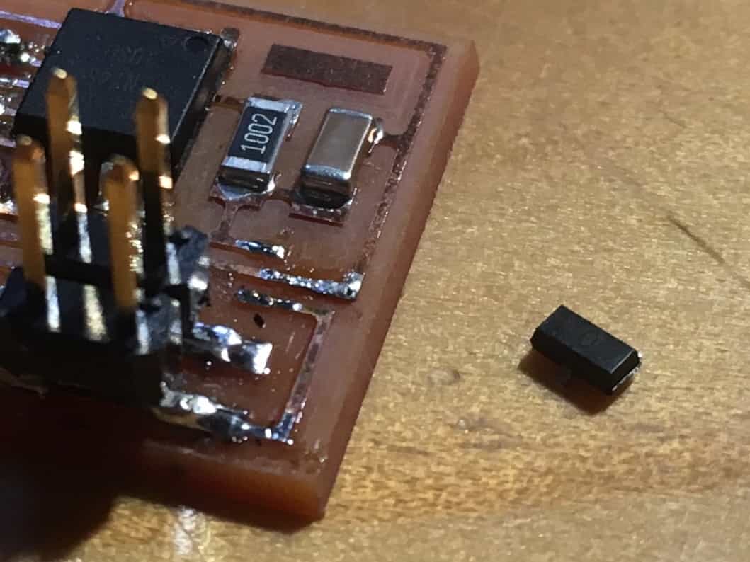
PROBLEM FIXED
1. When I first connected my board to power, the regulator burned a hole. I changed a new one but it was stilled burned. Then I found out that the regulator I had got was 3.3V, while my power supply is 5V. Therefore, I bought a new 5V regulator and solved the problem.
