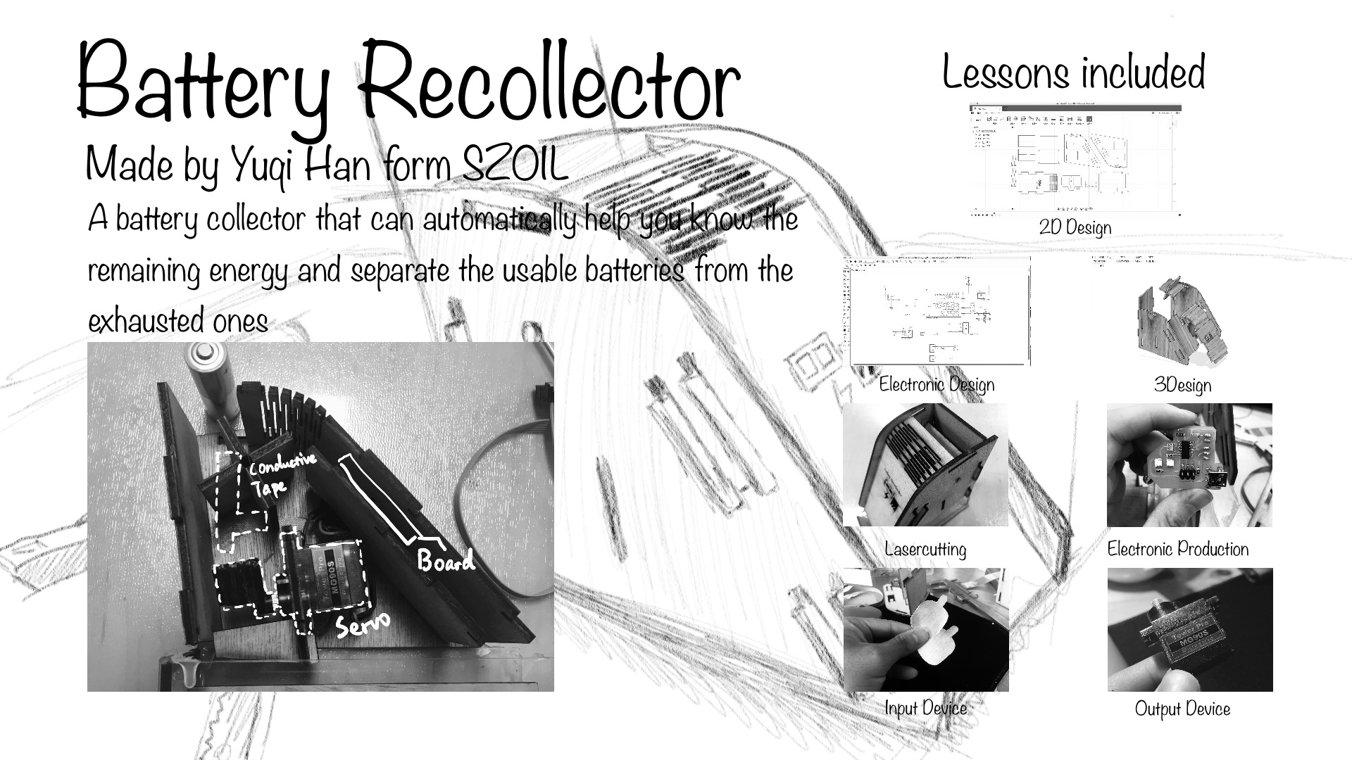
INTRODUCTION
Nowadays, batteries are getting more and more widely used, especially in the Maker Spaces. However, many of new batteries are thrown away mixed with the exhausted ones.
WORK DONE BY OTHERS
Then I remembered that a company called NANFU Batteries, which produces dry-cell batteries, had made a battery testing paper many years ago; it used a chemical way to display the battery level, and it is not for sale but only bundled with batteries on sale. Some people even made some analyzers for Li batteries and Pb batteries, however, no one had ever made a digital tester for the dry-cell batteries as I know.
MY IDEA
My goal is to use the lowest cost to make a dry-cell battery tester that can not only test the battery level, but can also separate the new ones from the ones that can no longer work. Since the battery recollector needs to transfer the battery level to a digital signal, not a chemical signal, I decided to use a microcontroller to read the battery voltage; battery voltage is directly related to the battery level. However, they do not have a linear relationship.
MATERIALS AND COST
| MATERIALS | COSTS |
|---|---|
| Plywood board 350mmx190mm | 0.06USD |
| FR3 PCB board | 0.38USD |
| LEDx4 | 0.03USD |
| Resistors:3Kx2,10Kx1 | 0.01USD |
| Capasitor: 10uf x1 | 0.01USD |
| ATtiny 44 x1 | 0.41USD |
| ICSP Jack and wires | From the old boards, 0.01USD |
| Conductive Tape 10cm | 0.01USD |
| Two 2mm nails | Much less than 0.01USD |
| Total | 0.93USD |
ELECTRONIC DESIGN / PRODUCTION
At first, I want to count the number of batteries, so I planned to use a LCD screen as an output device. However, using an LCD screen requires too many Pins, and LCD is a little expensive, relatively.
The second plan was to use an ATtiny 44 to read and display the battery level, then control the servo motor to separate batteries, and use a ATmega 328P to control a self–designed 14 LED array to display the number of batteries. This requires an on-board wired communication and it seems cool. However, when I really made the skematic and tried to route the board with EAGLE, the problem appeared: The only choice I had was to use a double-sided board, but I cannot do that with my desktop CNC milling machine! Also, ATmega 328P increases the cost, just for a counting function that is not very important. So I passed this plan and designed the final one.
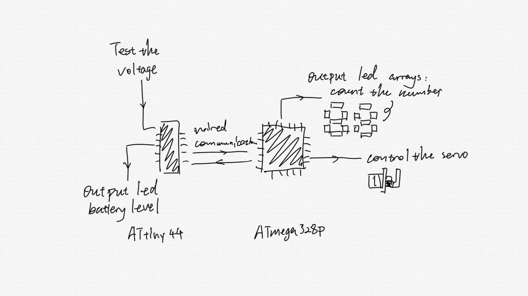
The second plan
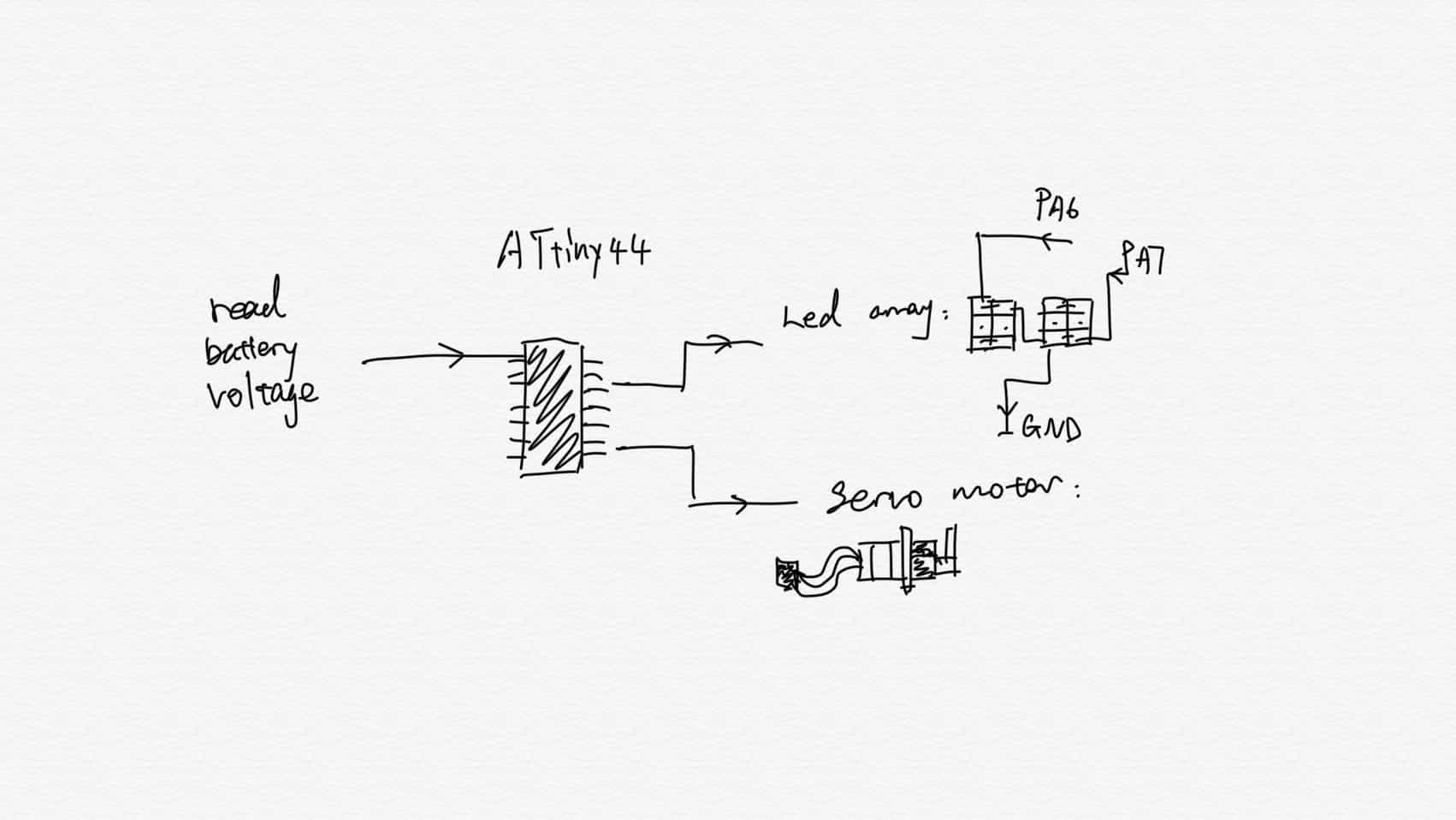
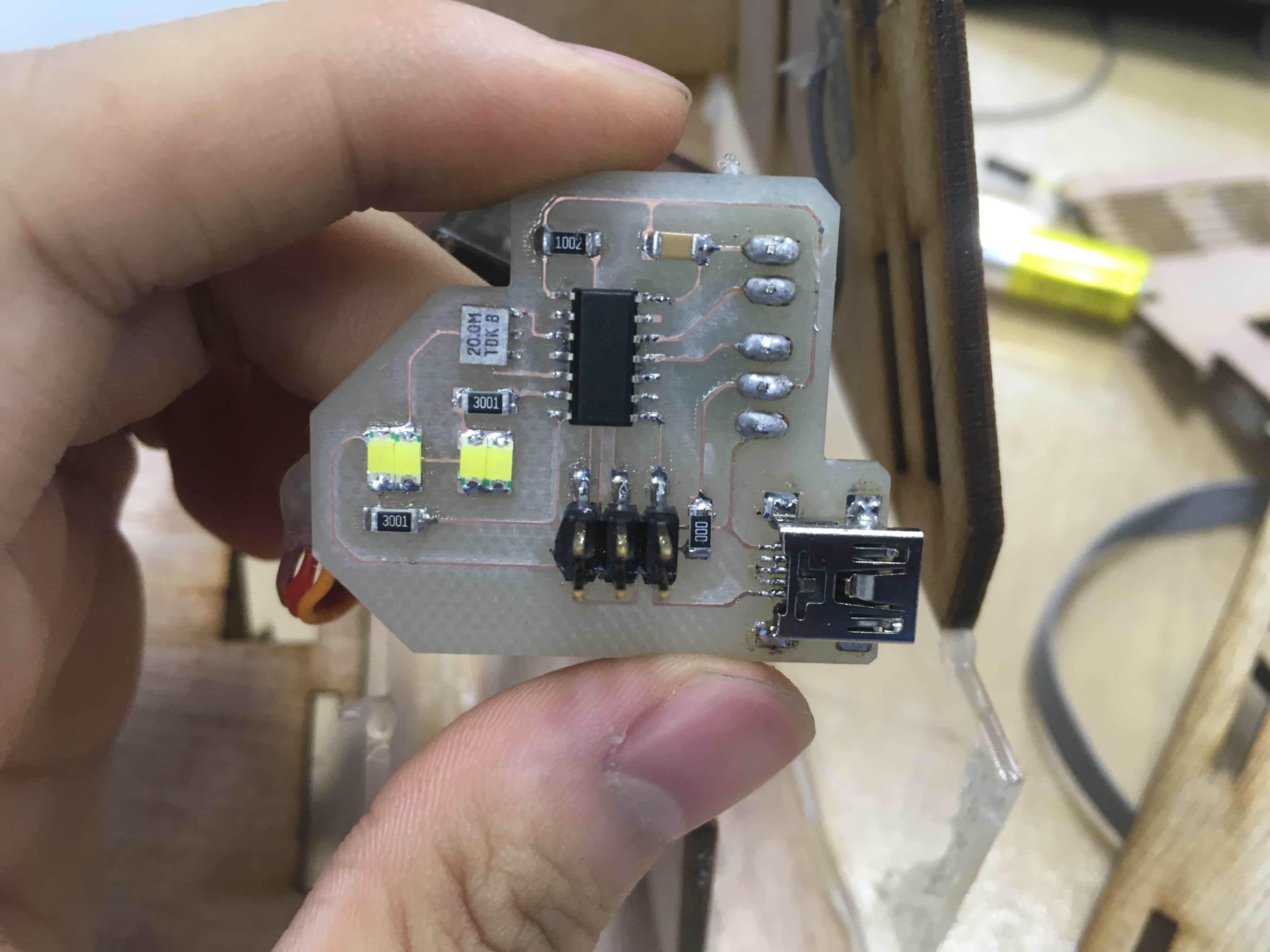
The final plan.
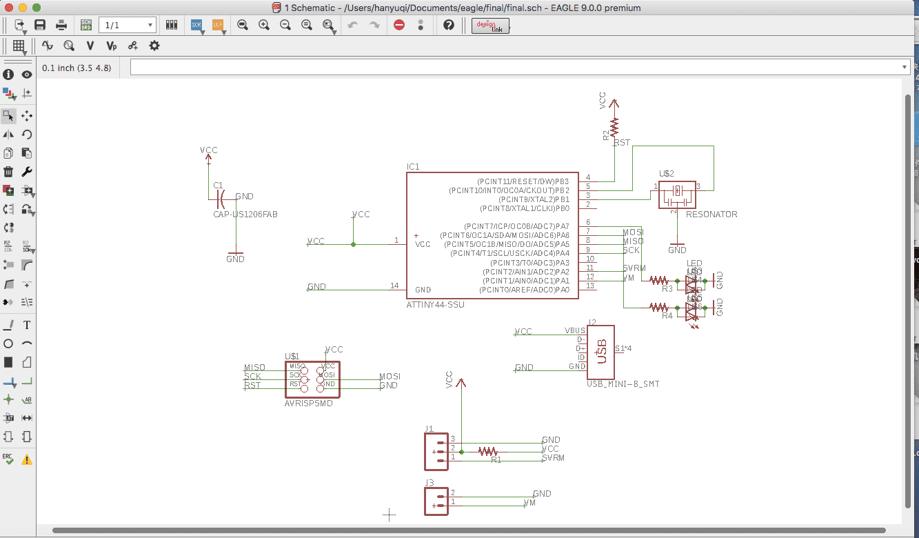
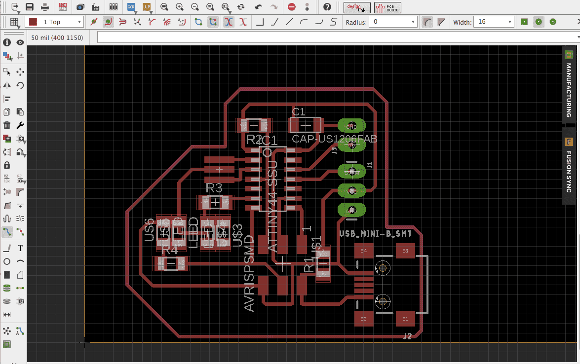
Then I dsigned the schematic and wired the board with EAGLE.
MECHANICAL DESIGN
I had been thinking about how to maintain the posture of the battery when it enters the recollector so that its voltage could be measured by the contact between two electrodes and the measuring poles. Then I came up with an idea: I can use a waterwheel-like rotating structure to achieve this: when the battery drop on the "waterwheel", the contact force between would help the battery to adjust its posture, while the retational inertia can provide enough time for this.
Then I draw the 2D skematic with Fusion 360.
HERE TO DOWNLOAD THE DXF FILES
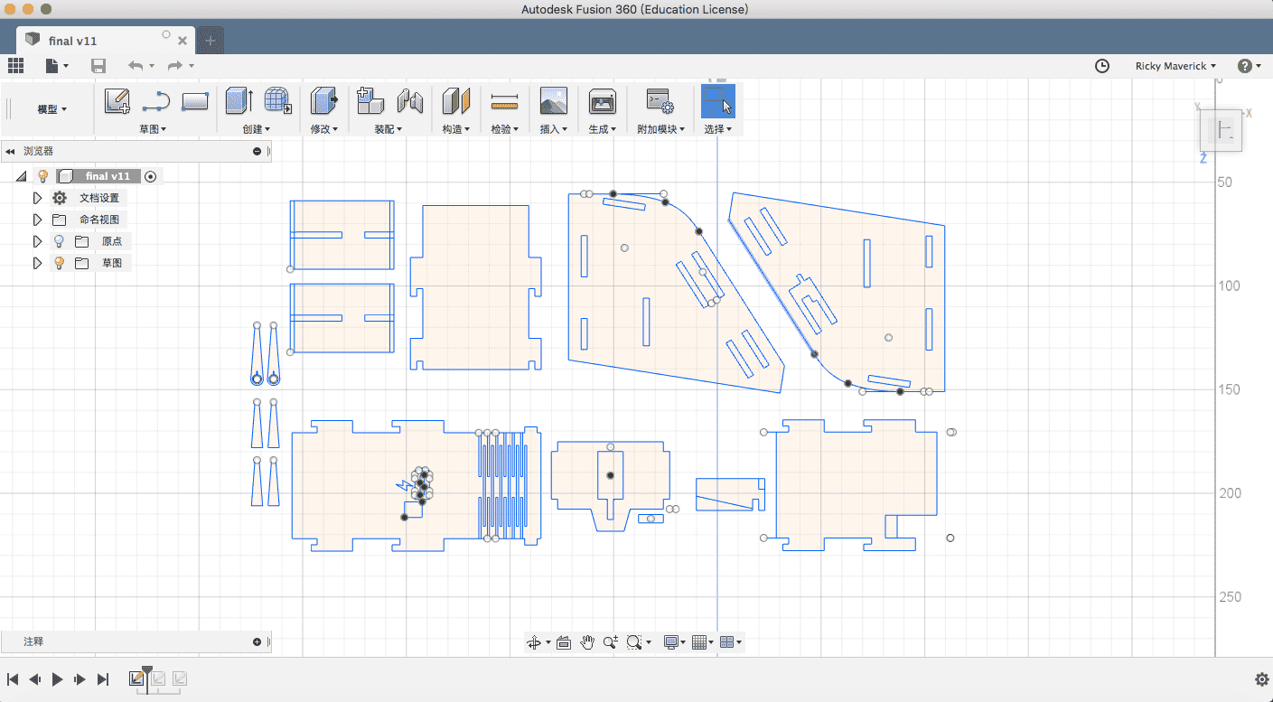
Then use the lasercutter to cut the density board, which is very easy and cheap.
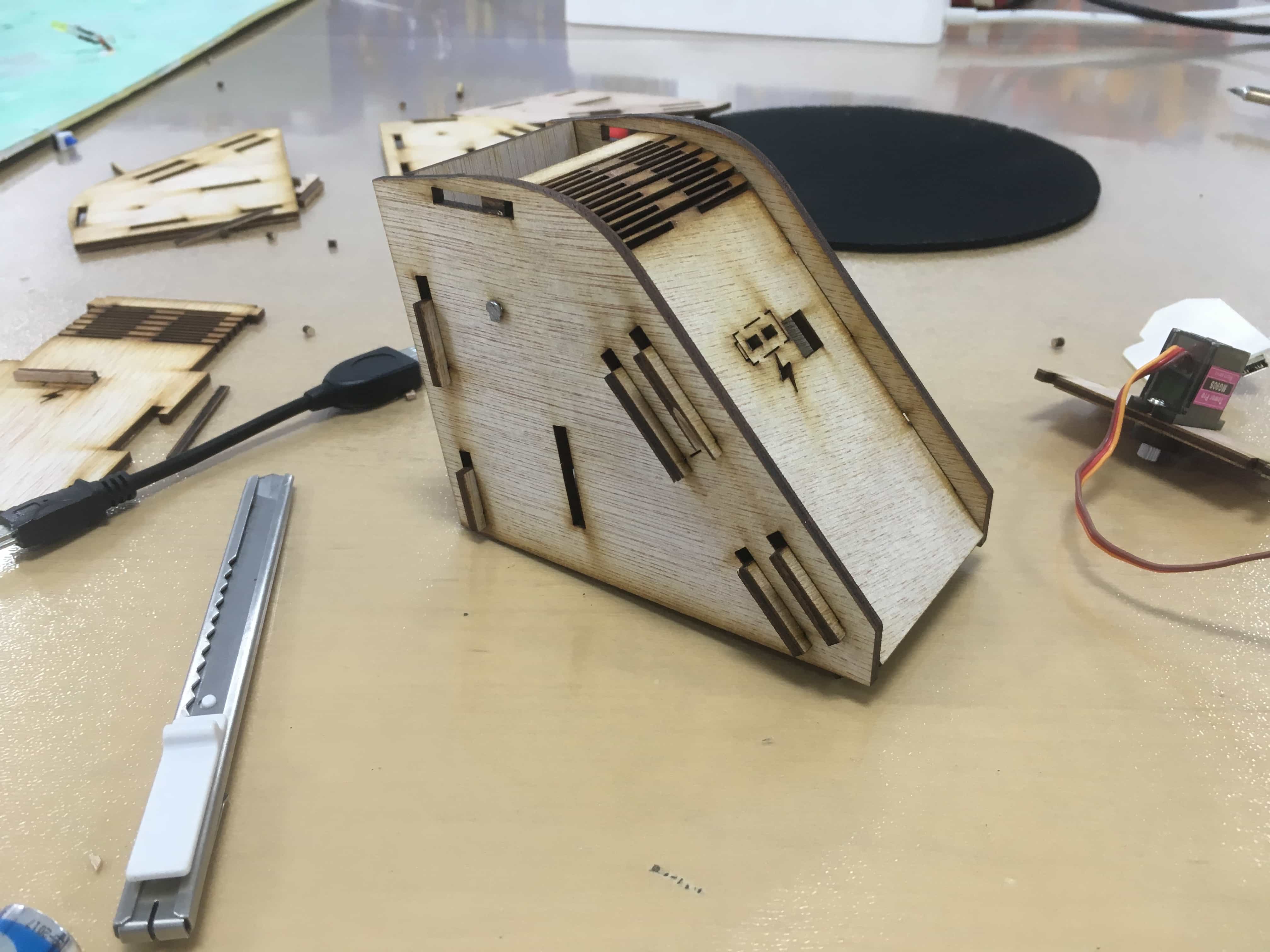
And then I assemble the case to see whether it needs some adjustment.
3D Design and Printing
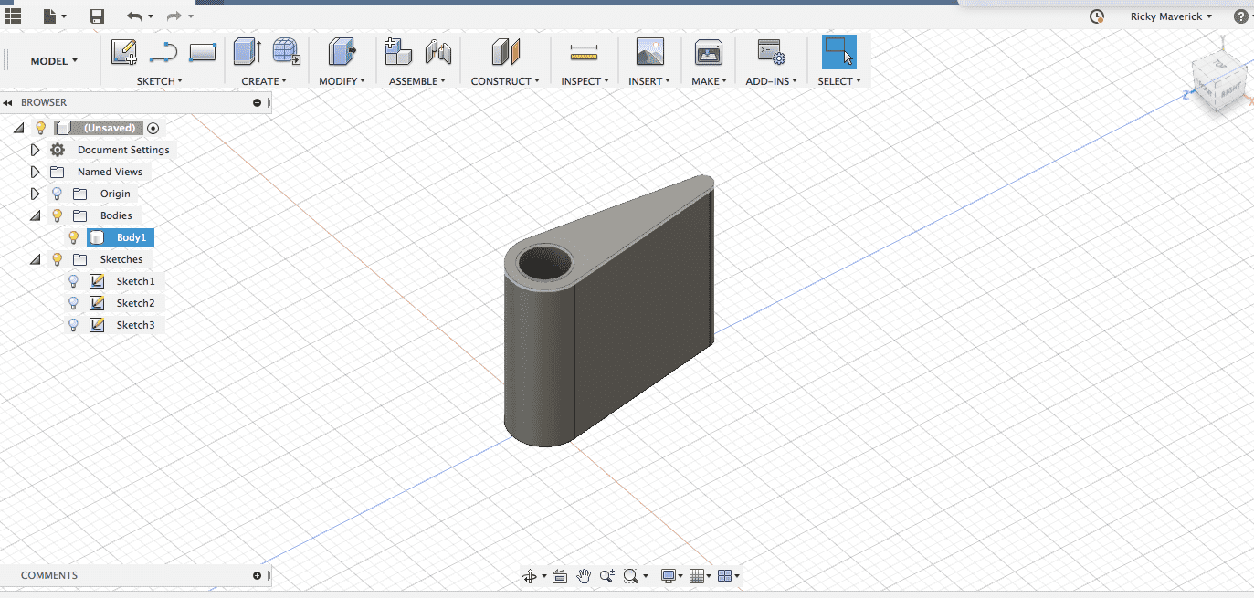
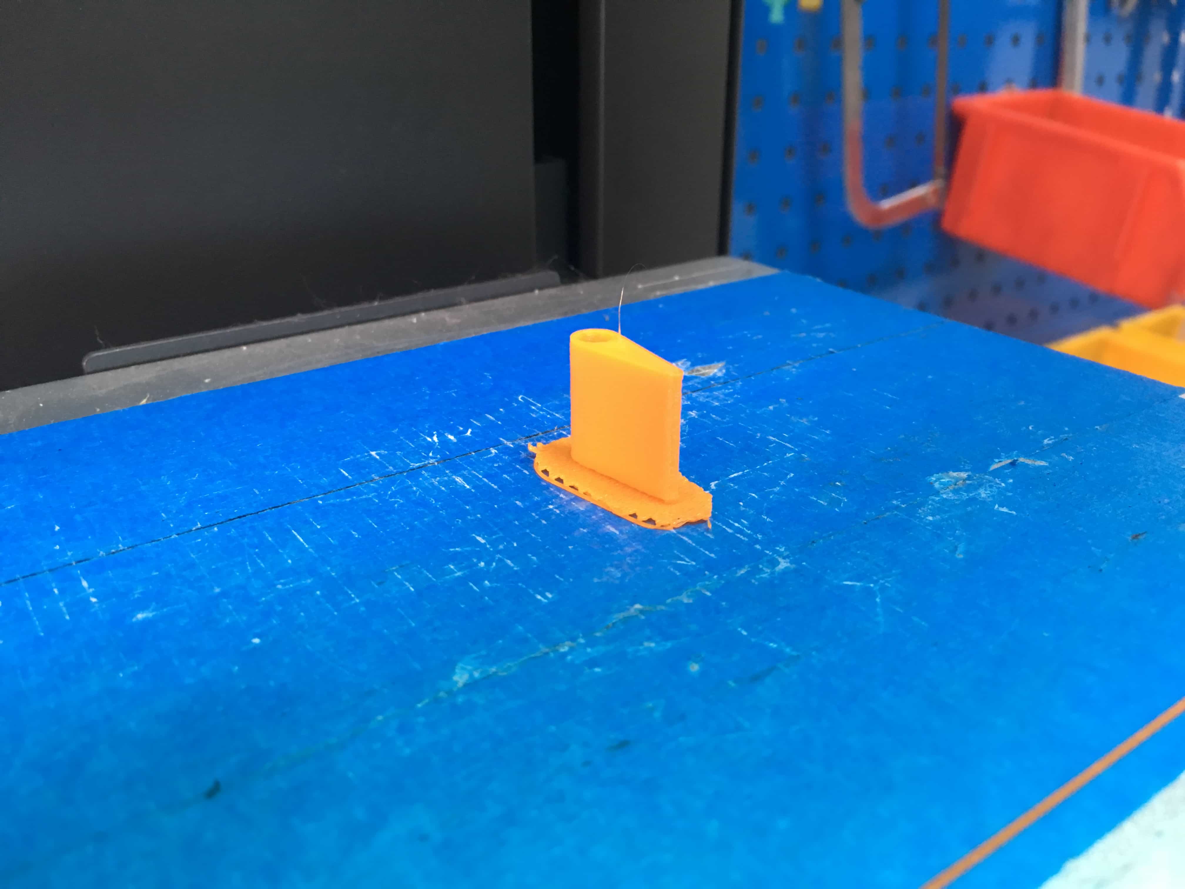
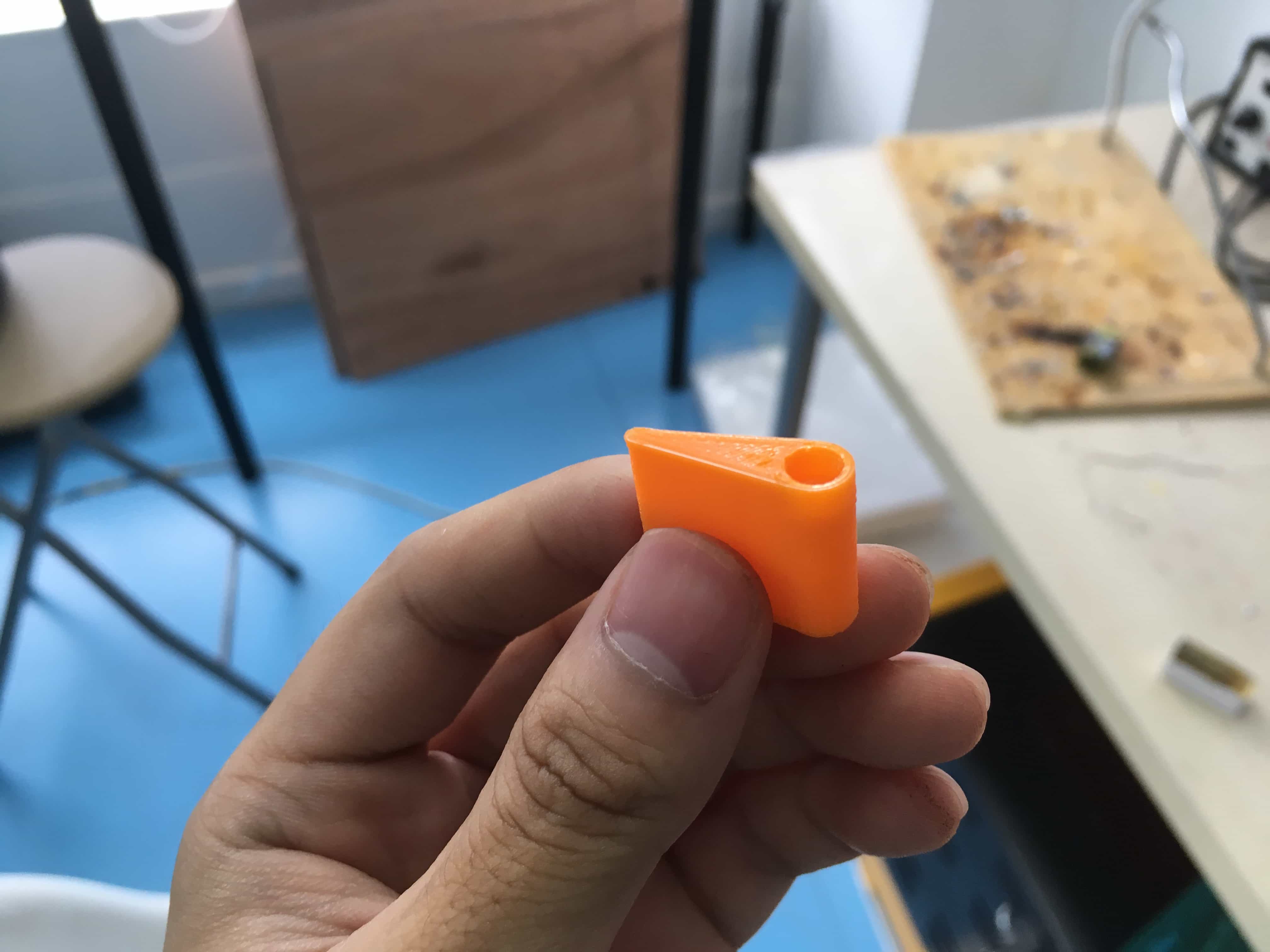
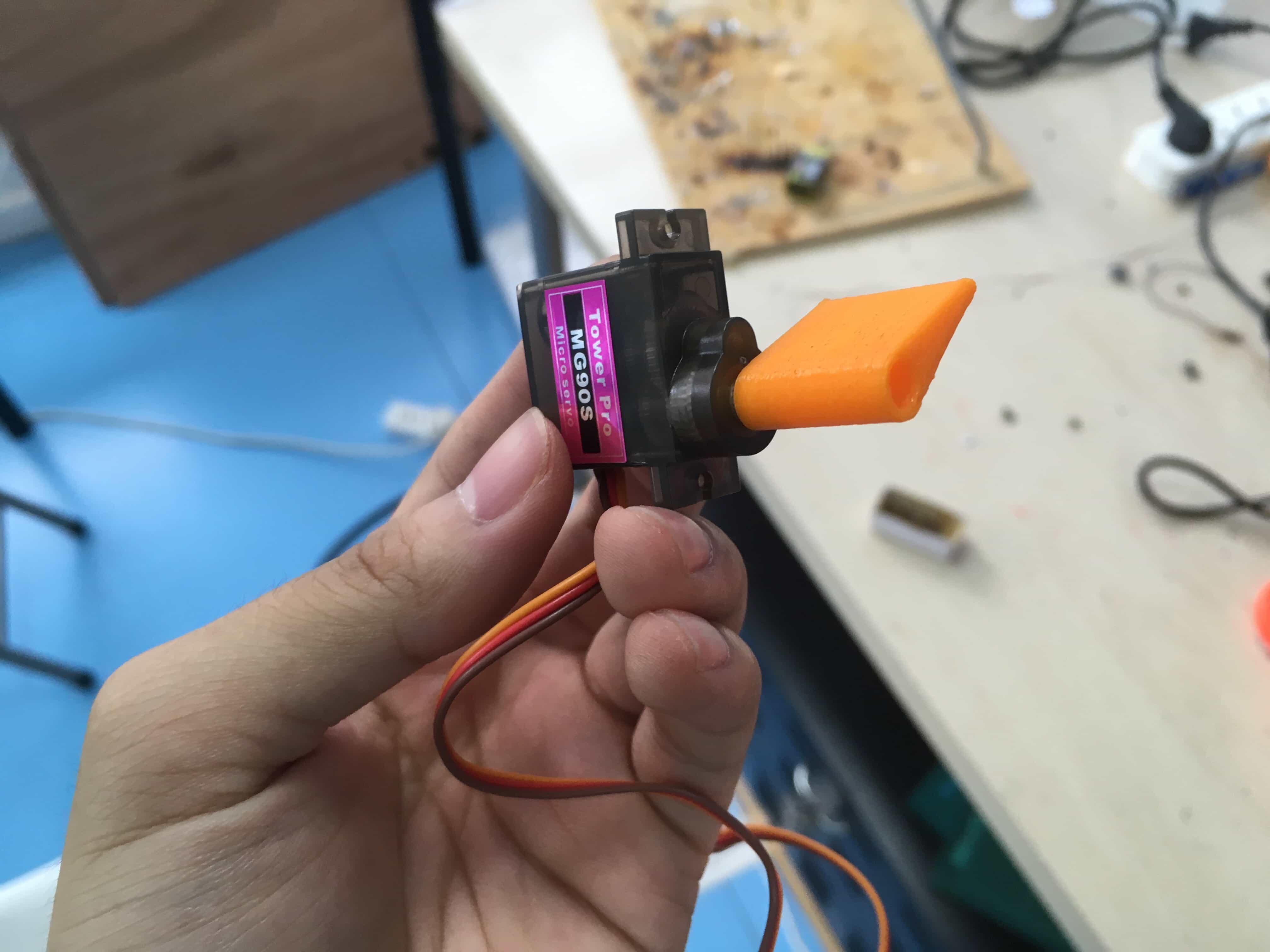
For the servo motor, I used Fusion 360 to design a 3D part as the direction panel.
 |
 |
 |
 |
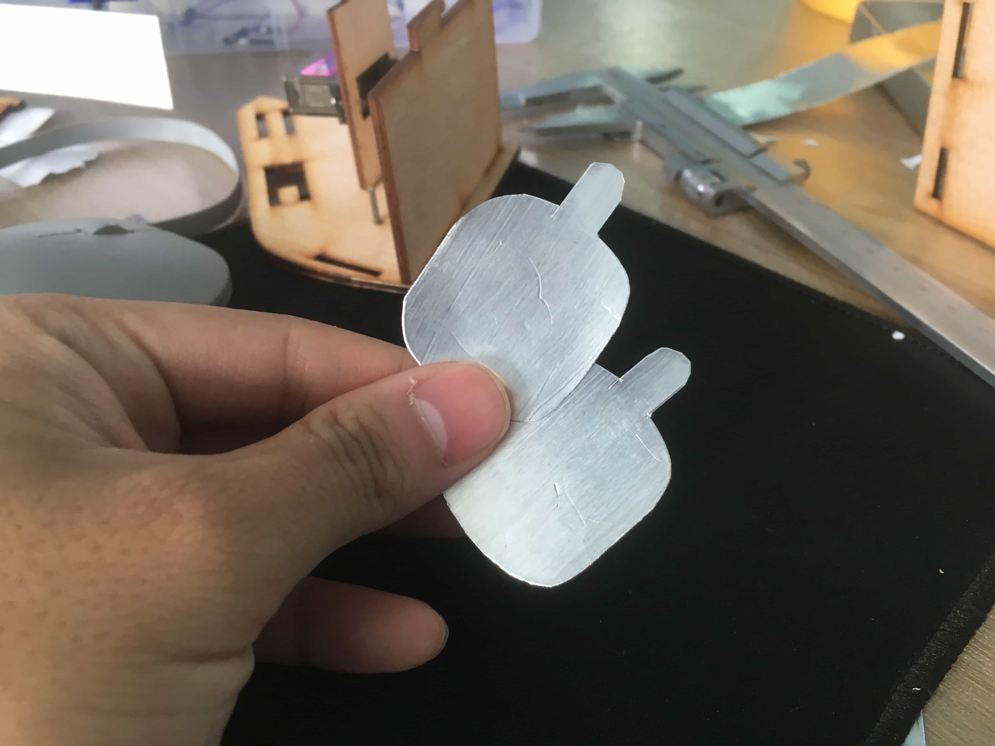
At first I wanted to use the conductive tape (wide one) to make the pole. However, I found out that this one is impossible to solder wires on it because it is made by aluminum, and aluminum would generate a oxided layer when heated, which made it neither conductive nor solderable. So I used another kind of conductive tape, which is made by metal fibers.
In fact, if I had more time, I would had bought copper foil and use a vinylcutter to cut out the shape.
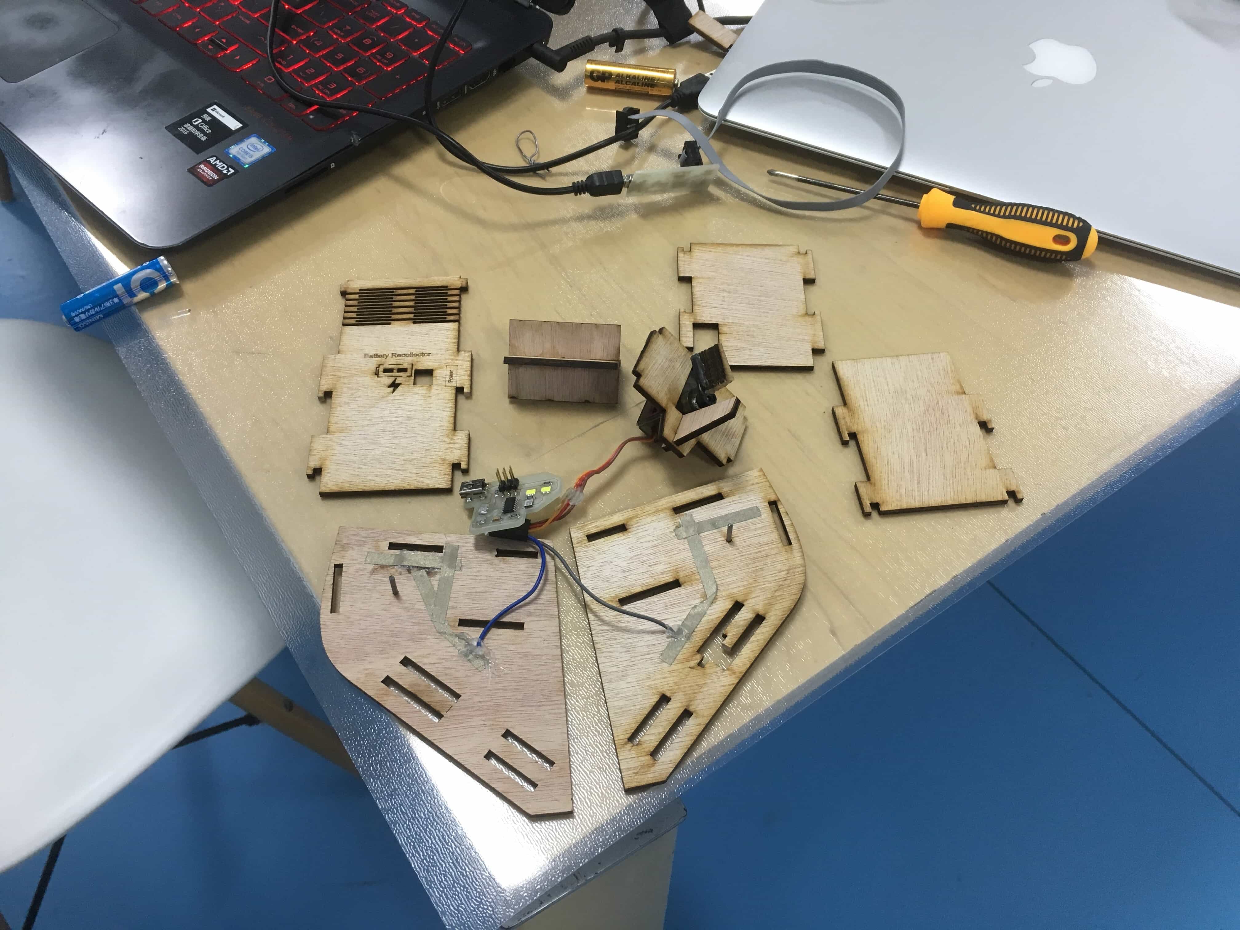
Here are all the parts.
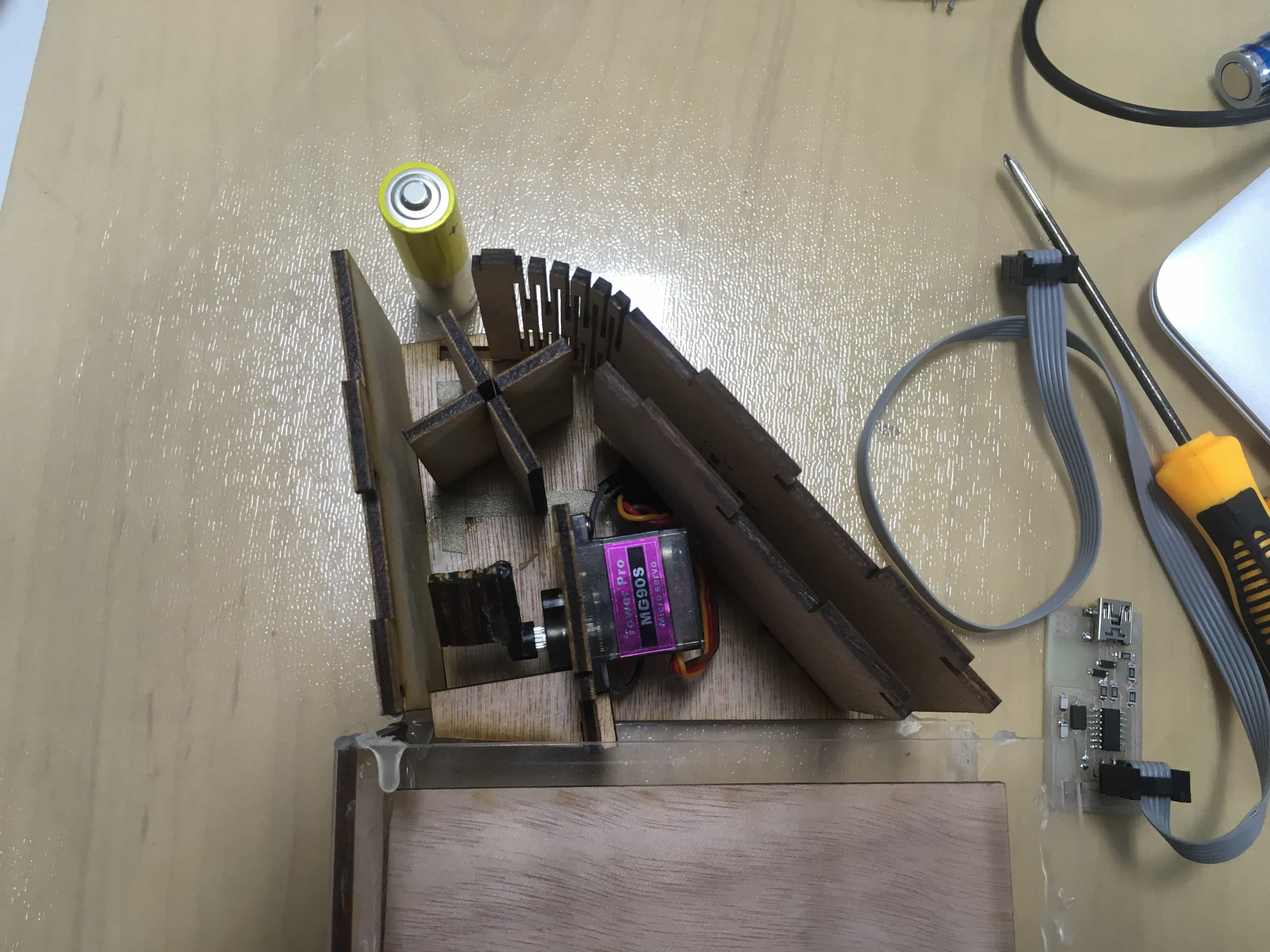
A side view of internal structure. You can see how the parts and board aligned.
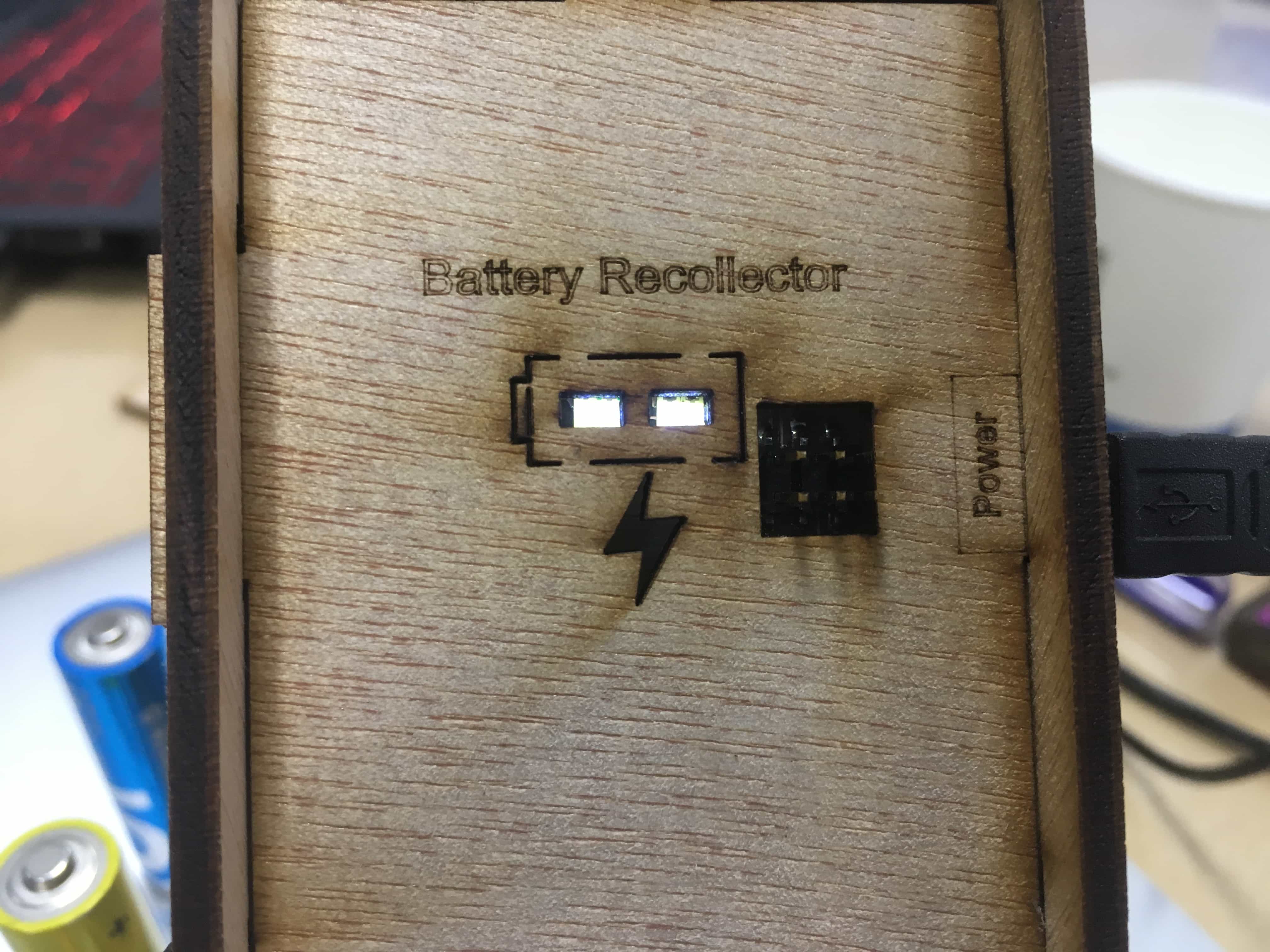
Display of battery level. Powered with mini USB dock.
Heroshot
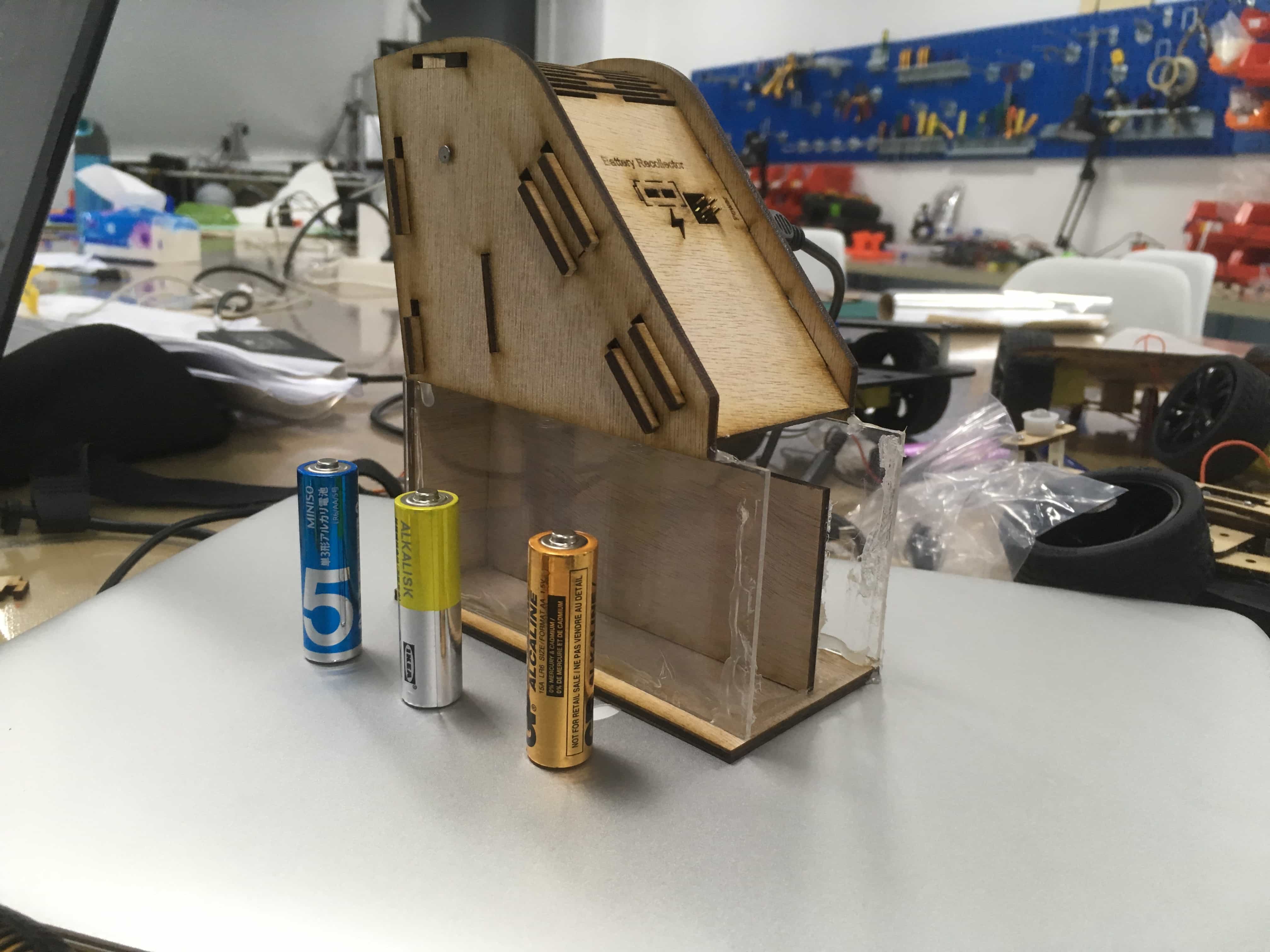
Finished.
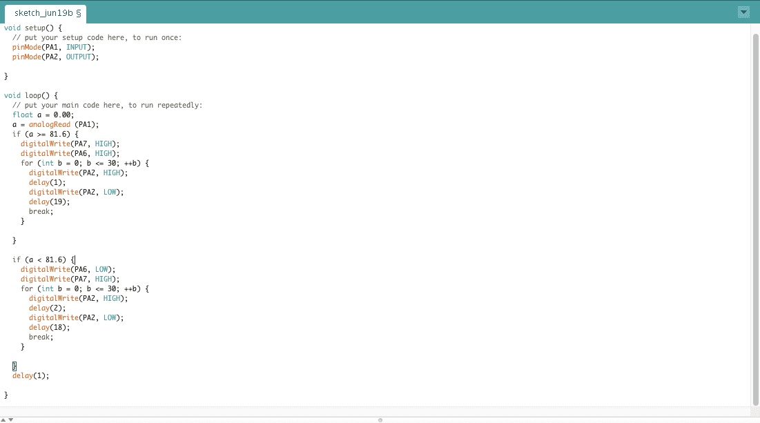
EMBEDED PROGRAMMING
Using arduino to program the board, I found it impossible to make the servo work with the library included. Then I went back to schedule and checked Neil's C file in OUTPUT DEVICES and got to know how the servo workes with PWM: the cycle must be 20ms, and the two polar directions are represented by 1ms output and 2ms output. Then I learned to program it with arduino IDE.
TESTING THE CIRCUIT / PRGRAMMING
Then I made several test on battery measurement and the servo to see if it could work well.
Servo test
Battery mearuement test
Overall function test
PROJECT DEVELOPEMENT
What tasks have been completed, and what tasks remain?
I have designed and made the prototype of the battery recollector. I only made one that could collect #5 batteries, but for #7 I haven't done yet.
What has worked? what hasn’t?
Most of the function worked. However, the measuring panels made of conducting tapes cannot work efficiently: they are small in area and create too much friction.
What questions need to be resolved?
1. Next time I will use vinylcutter to cut two copper panels so that the panel will have bigger touching area and better conductivity, also easier to be soldered with wires.
2. When the board does not read any voltages, the variable of measure voltage will be a radom number and it will cause the servo to "shake" and create a lot of noise. I can add another parallel circuit with a large resistor to make sure there is always a readable voltage.
What will happen when?
I plan to improve the parts above when I am free. And then I can consider to make the battery collector an affordable kit that can be distributed to any public trashcans or recollecting plots to help people better recollect the batteries.
What have you learned?
I learned how to really develop a project from zero and make it all by myself. Also, during the making process, I met some problems that forced me to review the previous lessons carefully (for example, I made mistakes for times when I was designing the PCB, and I had to go back to the datasheet and read it completely to figure out why in my previous versions Pins B are not usable). It really helped me to better understand what I had learned for months.
