Output Devices
Assignment
- add an output device to a microcontroller board you've designed, and program it to do something
Files
linear.array.44.zipfolder with c and make-file
LED array and Charlieplexing
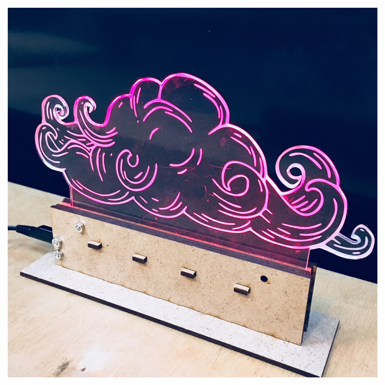
This week I am really interested in the LED array and Charlieplexing because I think it would fit perfectly for my final project. Last week I did some different step response boards (the hello.load.45 and the hello.txrx.45) in an attempt to find out how to design the input signal on my lamp. I ended up with figuring out (with a little help from Bas and Lorenzo) that the transmit recieve (txrx) is the way forward for my project. So now I am really curious about the Charlieplexing and will try to make a circuit that use 5 pins to control a linear array of 20 LEDs, a kind of LED-strip on PCB that could light up my engraved acrylic cloud.

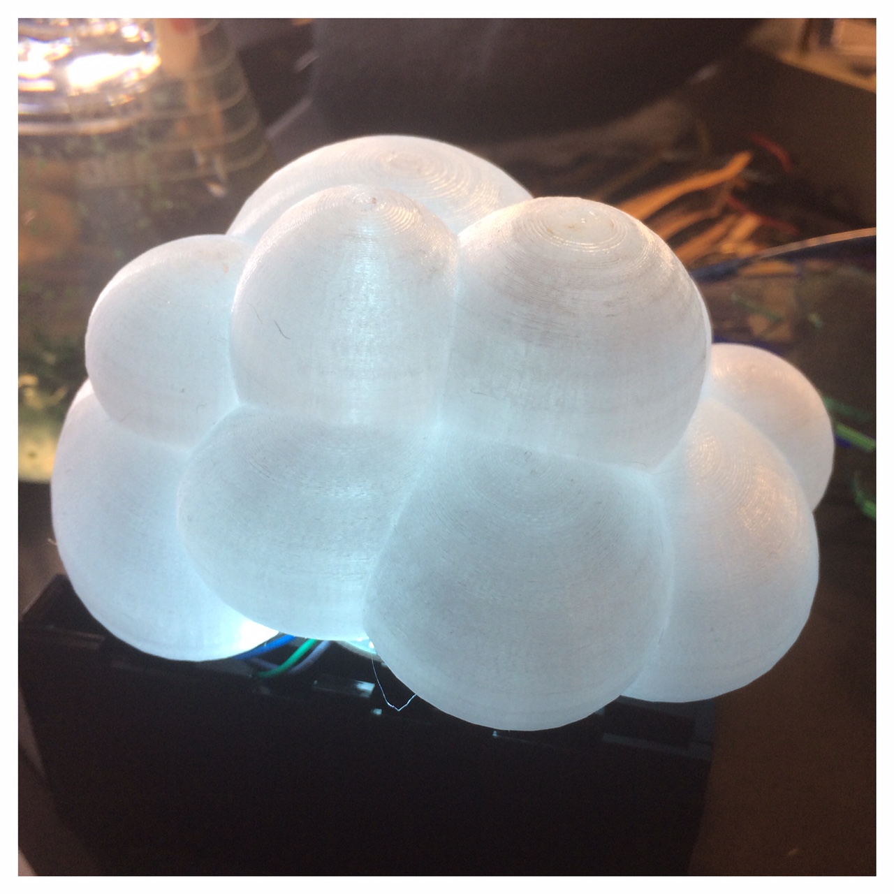
In order to understand how a circuit of multiple LED's or diodes should be constructed in terms of resistors and pins, I made this small narrow box with 11 diodes in. This makes it easier for me to understand the circuit and what should be my next step. I can also use the box for testing my engraved cloud.
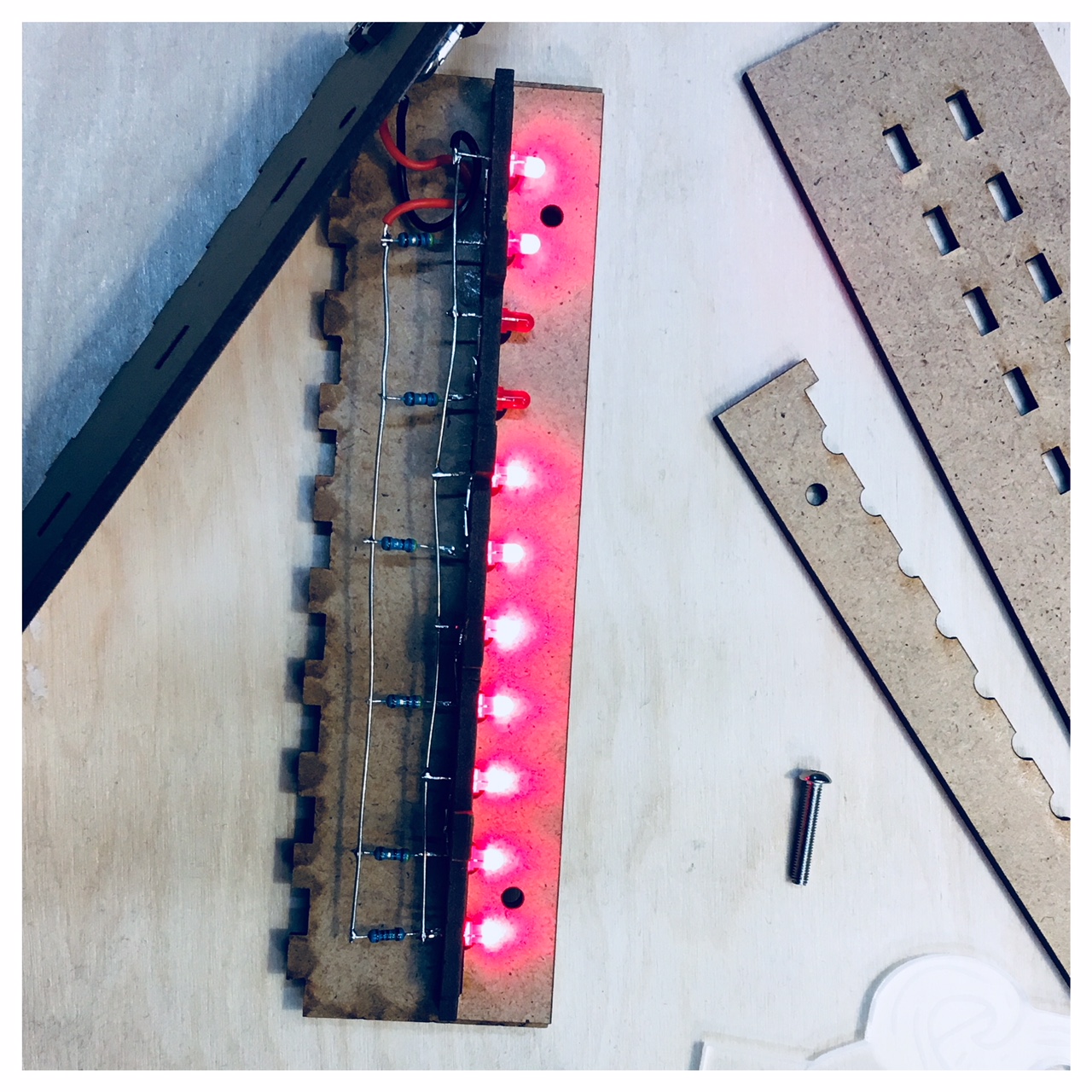
The thing is that I need to make a line of LED's instead of a square and try to understand how the different circuit paths are connected. I want to try to make a hello.array.44 board with a line of LED's that could light up my laser engraved acrylic cloud. On a Fab Academy site I found this guy Scott Zitek Zitek who made a ladder diagram with 20 different LED's wich gave a pretty good insight in how the circuit could be done. So I tried to make a rewrite of his hello.array.44 while while I constantly tjecked with Niel's hello.array.44. I wanted to make my board as long and narrow as posible so that it would fit inside my molded base.
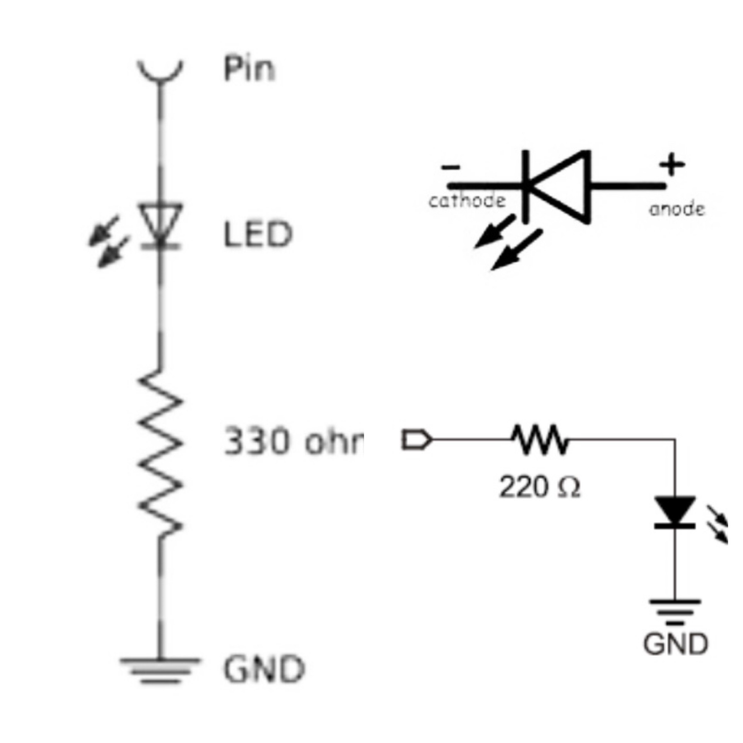
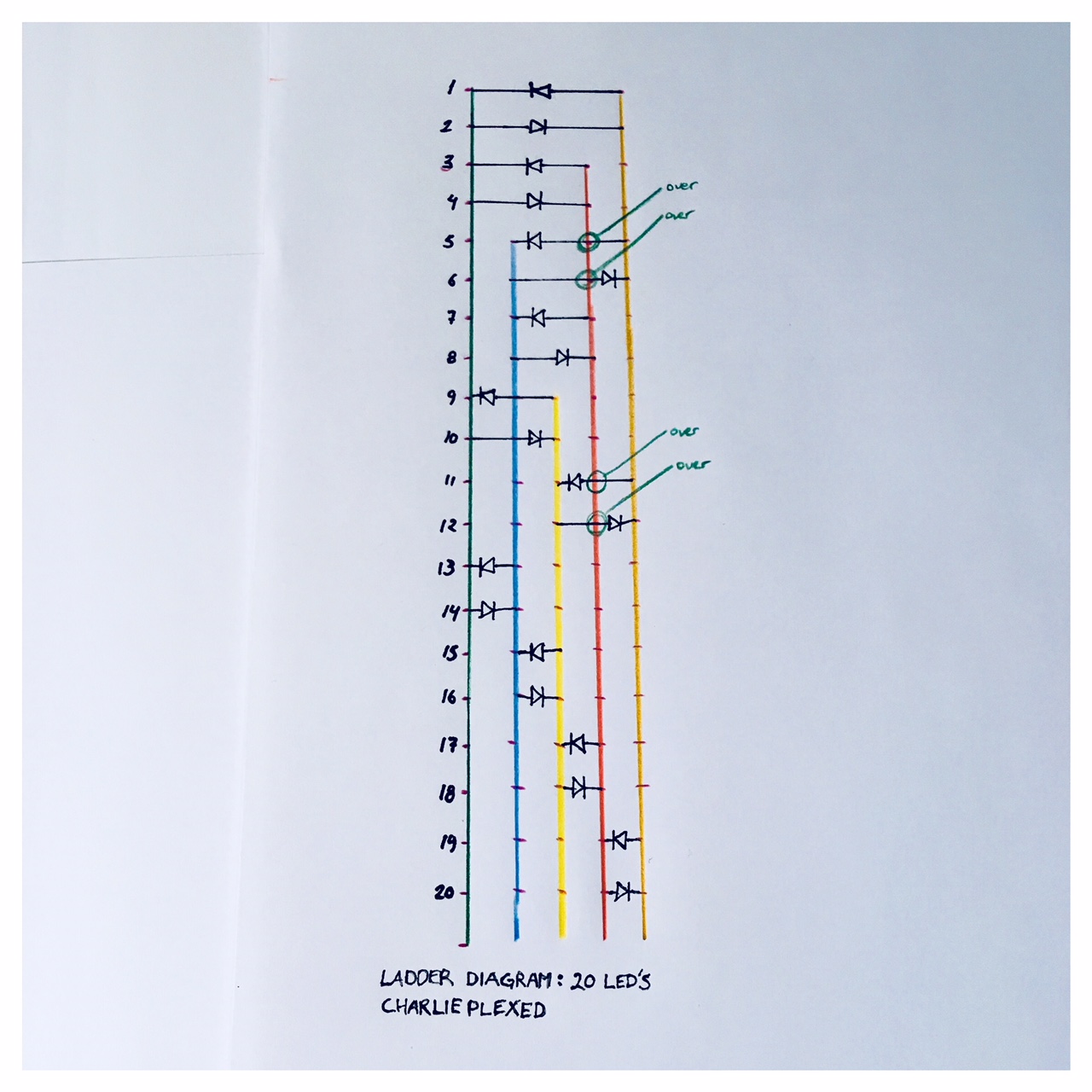
Now there were two things that I really had to study more. One is the schamatics of LED's and how to arrange the LEDs so that there were as few points in the circuit where the traces overlapped. I drew a ladder diagram with 20 LED's to keep a better overview and counted four places where I had to make a bridge with the LEDs.
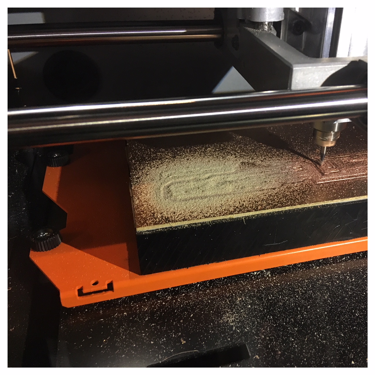
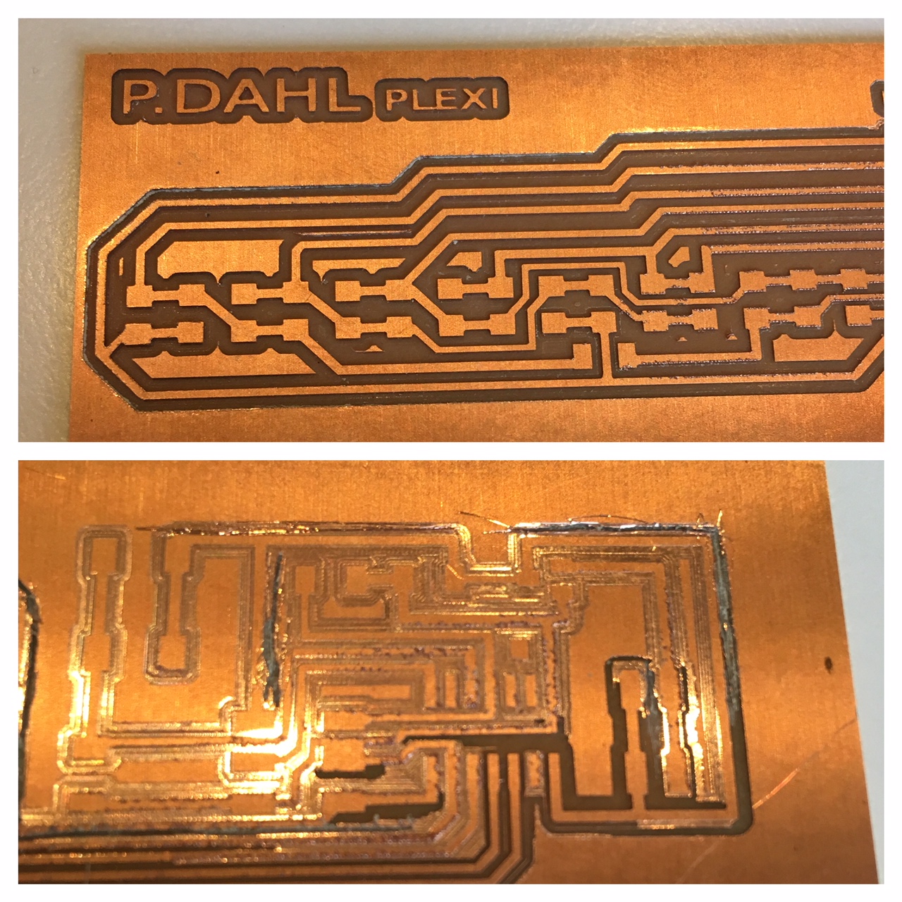
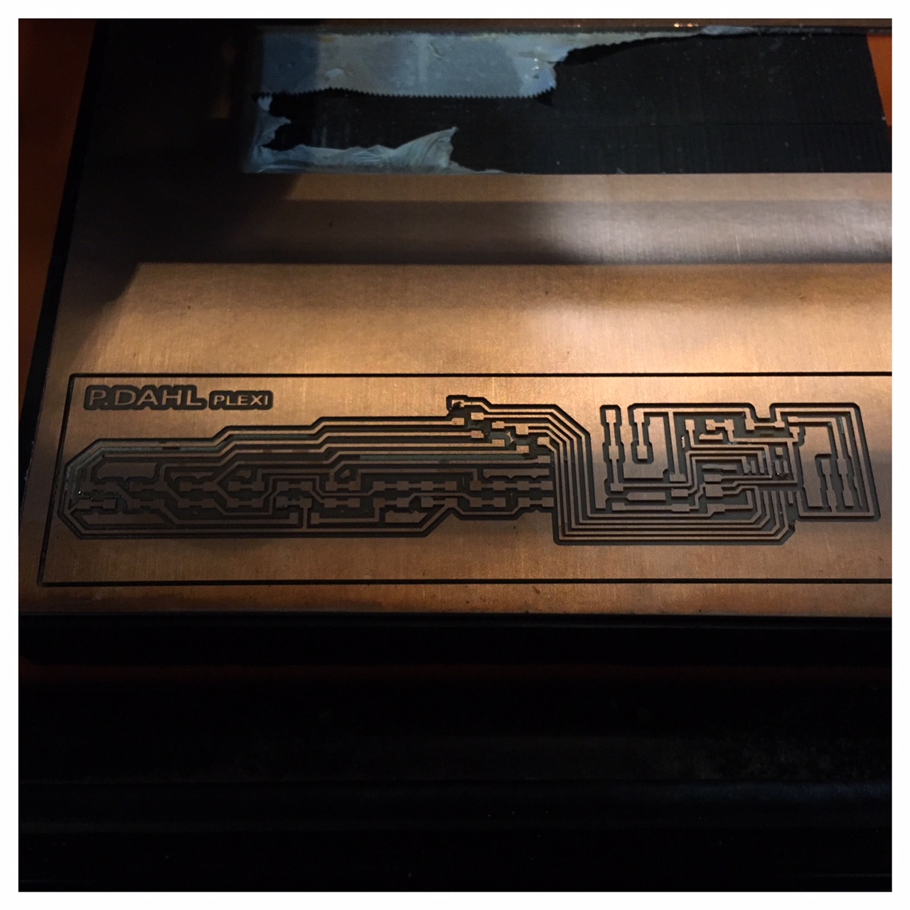
After the first milling job of my new board I ran into some problems with the milling proces. The Roland CNC had not cut the trace all the way through the copper at one of the the ends of my board (see the picture above). I thought I was quite thorough when I adjusted the milling bit and could not find an explanation for this error. But as I had investigated the matter a little more, I found out that the copper plate was curved or kind of crooked and therefore lay a little higher than the place where I first had adjusted the bit and when it was milling at the end did not go all the way through the PCB copper layer. So this really shows the importance of the PCB lying evenly and stright on the bottom plate.
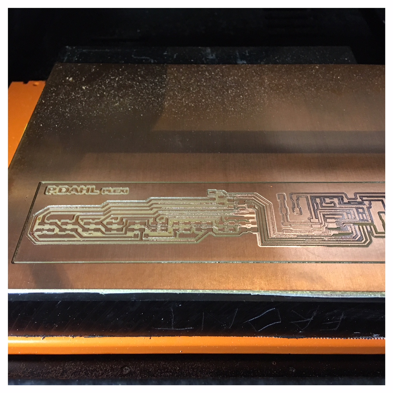
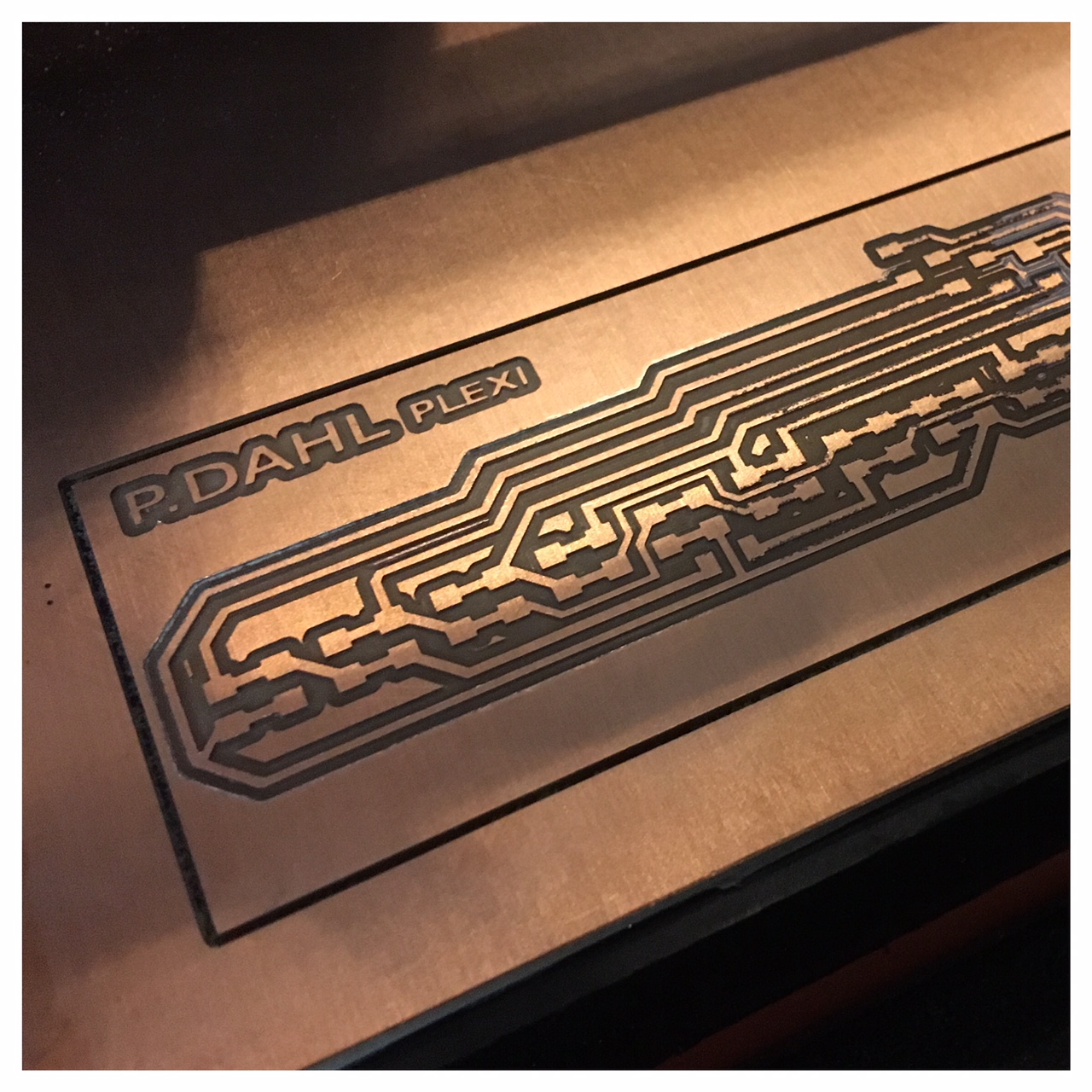
In my second attempt, the milling proces went much better and the result was good, so I was ready to solder my 20 LED's on.
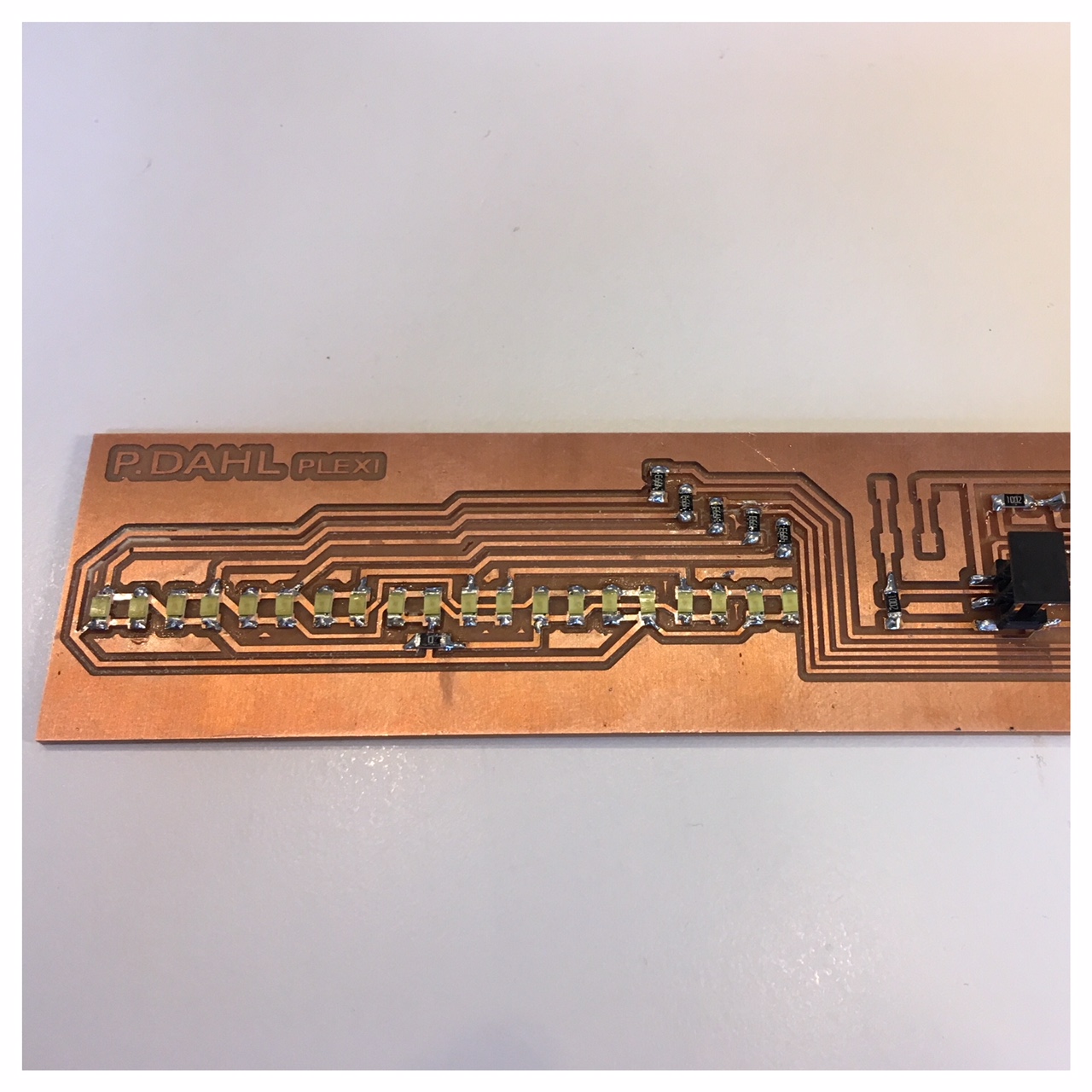
Soldering the circuit board went really great considering the number of components involved. I just really had to concentrate and pay special attention to make sure that each LED was facing the correct way.
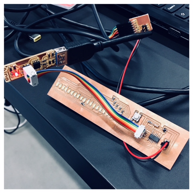
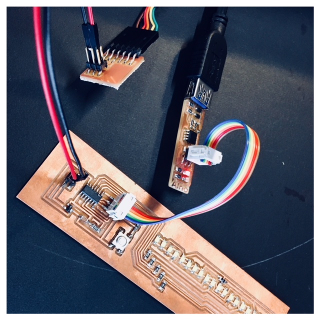
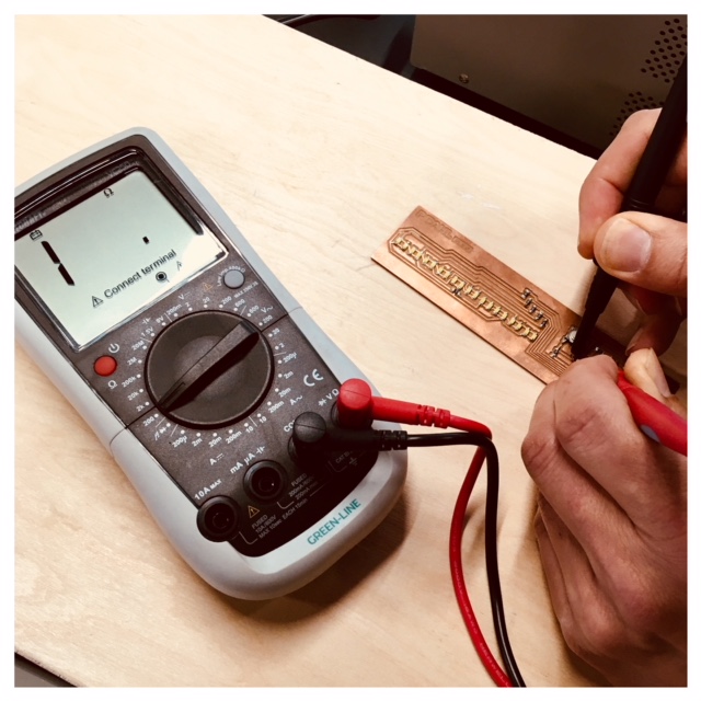
I burnt bootloader on my board and pushed the makefile and c-code for the board to make it Charlie Plex and everything went smooth, but sadly it didn't light up, something was wrong. I checked the traces and the LED's with the multimeter and checked the schematics again and it all seemed to be okay, but it still did not light up. Suddenly I discovered that it was lighting up but very weakly. When I held my hand over the LED's I could see it Charlie plexing but very weakly. So I was wondering if the missing brightness could be about the voltage regulator and came to that conclusion that I would change that. Then I found out together with our instructor that the 5V voltage regulators were put ind the wrong drawer. In the 5V drawer lay the 3.3V including the wrong datasheet and vice versa, so I soldered the wrong voltage regulator off and soldered the right one on. Sadly it still lit up very dimly, so I'm not done trouble shooting.
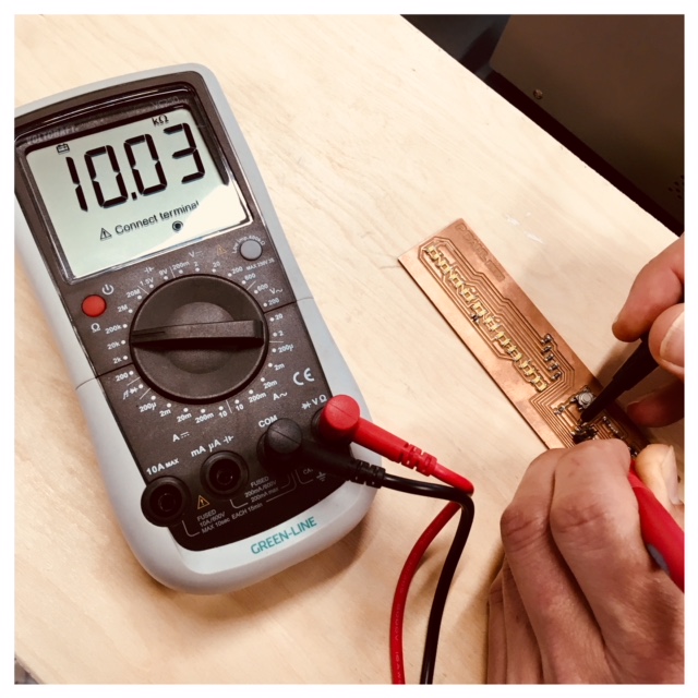
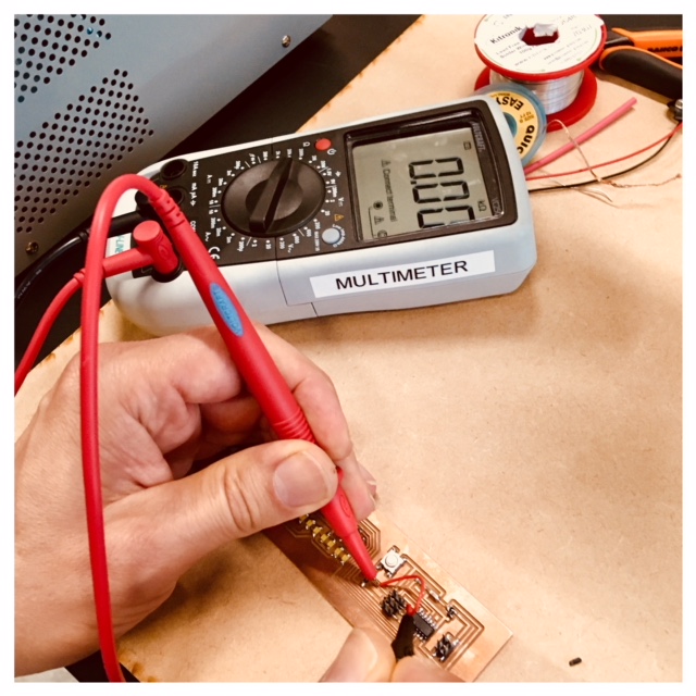
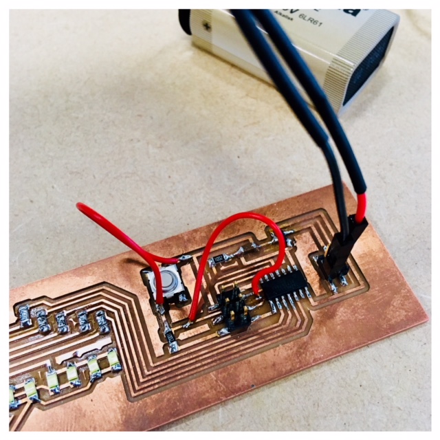
I checked again with the multimeter and powered it up to the board from the DC power supply we have in the lab. From this machine I could control the voltage and the ampere. I found out that there was one trace that went through the header that was working similarly to a resistor. I soldered a cord to the trace and made a bridge. This helped and the right amount of voltage went through the trace now. I also tried to solder a bridge over the pushbutton because it seemed a bit less responsive.
Watch the video below of my Output board, LED array, Charlieplexing.
Code used for Charlieplexing
Charlieplexing is a technique for running a multiplexed display (in my case 20 LED's in a row) in which relatively few I/O pins on a microcontroller are used to drive an array of LED's. The method uses the capabilities of a microcontroller to gain efficiency over traditional multiplexing.
Below you can see the code I have used for my Chalie Plexing board. I will try -with my own words- to explain parts of the code in the comments in the actual code. You can find the comments in the code after the two back slashes //
//
//
// linear.array.44.pbv1.c
//
// Charlieplex LED array hello-world
//
// Neil Gershenfeld
// 11/13/10
//
// (c) Massachusetts Institute of Technology 2010
// Permission granted for experimental and personal use;
// license for commercial sale available from MIT.
//

// Modified 4/22/2014 by Scott Zitek
// Code used with a modified output board and working (after e few modifications, please check my student site) 15/04/2018 by Peter Dahl during FabAcademy2018

#include < avr/io.h >
#include < util/delay.h >

#define output(directions,pin) (directions |= pin) // set port direction for output, this is where the output is defined.
#define input(directions,pin) (directions &= (~pin)) // set port direction for input, this is where the input is defined.
#define set(port,pin) (port |= pin) // set port pin
#define clear(port,pin) (port &= (~pin)) // clear port pin
#define pin_test(pins,pin) (pins & pin) // test for port pin
#define bit_test(byte,bit) (byte & (1 << bit)) // test for bit set

#define input_port PORTB
#define input_direction DDRB
#define input_pin (1 << PB2)
#define input_pins PINB

#define led_delay() _delay_ms(1) // LED delay

#define led_port PORTA
#define led_direction DDRA

#define A (1 << PA1) // row 1
#define B (1 << PA2) // row 2
#define C (1 << PA3) // row 3
#define D (1 << PA4) // row 4
#define E (1 << PA5) // row 5

 uint8_t  pbstate;   //button state
 uint8_t  pblast;  //button last pass
 uint8_t  pboneshot; //button pressed oneshot
 uint8_t  mode; //0-5

void flash(uint8_t from, uint8_t to, uint8_t delay) {
   //
   // source from, sink to, flash
   //
   static uint8_t i;
   set(led_port,from);
   clear(led_port,to);
   output(led_direction,from);
   output(led_direction,to);
   for (i = 0; i < delay; ++i)
       led_delay();
   input(led_direction,from);
   input(led_direction,to);
   }

void led_cycle(uint8_t number, uint8_t delay) {
   //
   // cycle through LEDs
   //
   uint8_t i;
   for (i = 0; i < number; ++i) {
   //
   //This is a loop that checkes that as long as "i" is smaler than the number then it runs the code part.
   //When "i" is larger than the number then it goes further un to the next part of the code.
   //"i" is equal 0 but everytime it runs the loop it adds +1 to "i".
   //

	 // LEDs 20 to 1
      flash(D,E,delay);   // LED20
      flash(E,D,delay);   // LED19
      flash(C,D,delay);   // LED18
      flash(D,C,delay);   // LED17
      flash(B,C,delay);   // LED16
      flash(C,B,delay);   // LED15
      flash(A,B,delay);   // LED14
      flash(B,A,delay);   // LED13
      flash(C,E,delay);   // LED12
      flash(E,C,delay);   // LED11
      flash(A,C,delay);   // LED10
      flash(C,A,delay);   // LED9
      flash(B,D,delay);   // LED8
      flash(D,B,delay);   // LED7
      flash(B,E,delay);   // LED6
      flash(E,B,delay);   // LED5
      flash(A,D,delay);   // LED4
      flash(D,A,delay);   // LED3
      flash(A,E,delay);   // LED2
      flash(E,A,delay);   // LED1

      // LEDs 1 to 20
      flash(E,A,delay);   // LED1
      flash(A,E,delay);   // LED2
      flash(D,A,delay);   // LED3
      flash(A,D,delay);   // LED4
      flash(E,B,delay);   // LED5
      flash(B,E,delay);   // LED6
      flash(D,B,delay);   // LED7
      flash(B,D,delay);   // LED8
      flash(C,A,delay);   // LED9
      flash(A,C,delay);   // LED10
      flash(E,C,delay);   // LED11
      flash(C,E,delay);   // LED12
      flash(B,A,delay);   // LED13
      flash(A,B,delay);   // LED14
      flash(C,B,delay);   // LED15
      flash(B,C,delay);   // LED16
      flash(D,C,delay);   // LED17
      flash(C,D,delay);   // LED18
      flash(E,D,delay);   // LED19
      flash(D,E,delay);   // LED20
      }
   }

void led_cycle2(uint8_t number, uint8_t delay) {
   //
   // cycle through LEDs
   //
   uint8_t i;
   for (i = 0; i < number; ++i) {

 	 // LEDs alternate sides towards center
      flash(D,E,delay);   // LED20
      flash(E,A,delay);   // LED1
      flash(E,D,delay);   // LED19
      flash(A,E,delay);   // LED2
      flash(C,D,delay);   // LED18
      flash(D,A,delay);   // LED3
      flash(D,C,delay);   // LED17
      flash(A,D,delay);   // LED4
      flash(B,C,delay);   // LED16
      flash(E,B,delay);   // LED5
      flash(C,B,delay);   // LED15
      flash(B,E,delay);   // LED6
      flash(A,B,delay);   // LED14
      flash(D,B,delay);   // LED7
      flash(B,A,delay);   // LED13
      flash(B,D,delay);   // LED8
      flash(C,E,delay);   // LED12
      flash(C,A,delay);   // LED9
      flash(E,C,delay);   // LED11
      flash(A,C,delay);   // LED10

 	 // LEDs alternate sides towards outside
      flash(A,C,delay);   // LED10
      flash(E,C,delay);   // LED11
      flash(C,A,delay);   // LED9
      flash(C,E,delay);   // LED12
      flash(B,D,delay);   // LED8
      flash(B,A,delay);   // LED13
      flash(D,B,delay);   // LED7
      flash(A,B,delay);   // LED14
      flash(B,E,delay);   // LED6
      flash(C,B,delay);   // LED15
      flash(E,B,delay);   // LED5
      flash(B,C,delay);   // LED16
      flash(A,D,delay);   // LED4
      flash(D,C,delay);   // LED17
      flash(D,A,delay);   // LED3
      flash(C,D,delay);   // LED18
      flash(A,E,delay);   // LED2
      flash(E,D,delay);   // LED19
      flash(E,A,delay);   // LED1
      flash(D,E,delay);   // LED20
      }
   }

void led_cycle3(uint8_t number, uint8_t delay) {
   //
   // cycle through LEDs
   //
   uint8_t i;
   for (i = 0; i < number; ++i) {

	 // LEDs 20 to 1
      flash(D,E,delay);   // LED20
      flash(E,D,delay);   // LED19
      flash(C,D,delay);   // LED18
      flash(D,C,delay);   // LED17
      flash(B,C,delay);   // LED16
      flash(C,B,delay);   // LED15
      flash(A,B,delay);   // LED14
      flash(B,A,delay);   // LED13
      flash(C,E,delay);   // LED12
      flash(E,C,delay);   // LED11
      flash(A,C,delay);   // LED10
      flash(C,A,delay);   // LED9
      flash(B,D,delay);   // LED8
      flash(D,B,delay);   // LED7
      flash(B,E,delay);   // LED6
      flash(E,B,delay);   // LED5
      flash(A,D,delay);   // LED4
      flash(D,A,delay);   // LED3
      flash(A,E,delay);   // LED2
      flash(E,A,delay);   // LED1

      // LEDs 1 to 20
      flash(E,A,delay);   // LED1
      flash(A,E,delay);   // LED2
      flash(D,A,delay);   // LED3
      flash(A,D,delay);   // LED4
      flash(E,B,delay);   // LED5
      flash(B,E,delay);   // LED6
      flash(D,B,delay);   // LED7
      flash(B,D,delay);   // LED8
      flash(C,A,delay);   // LED9
      flash(A,C,delay);   // LED10
      flash(E,C,delay);   // LED11
      flash(C,E,delay);   // LED12
      flash(B,A,delay);   // LED13
      flash(A,B,delay);   // LED14
      flash(C,B,delay);   // LED15
      flash(B,C,delay);   // LED16
      flash(D,C,delay);   // LED17
      flash(C,D,delay);   // LED18
      flash(E,D,delay);   // LED19
      flash(D,E,delay);   // LED20

 	 // LEDs alternate sides towards center
      flash(D,E,delay);   // LED20
      flash(E,A,delay);   // LED1
      flash(E,D,delay);   // LED19
      flash(A,E,delay);   // LED2
      flash(C,D,delay);   // LED18
      flash(D,A,delay);   // LED3
      flash(D,C,delay);   // LED17
      flash(A,D,delay);   // LED4
      flash(B,C,delay);   // LED16
      flash(E,B,delay);   // LED5
      flash(C,B,delay);   // LED15
      flash(B,E,delay);   // LED6
      flash(A,B,delay);   // LED14
      flash(D,B,delay);   // LED7
      flash(B,A,delay);   // LED13
      flash(B,D,delay);   // LED8
      flash(C,E,delay);   // LED12
      flash(C,A,delay);   // LED9
      flash(E,C,delay);   // LED11
      flash(A,C,delay);   // LED10

 	 // LEDs alternate sides towards outside
      flash(A,C,delay);   // LED10
      flash(E,C,delay);   // LED11
      flash(C,A,delay);   // LED9
      flash(C,E,delay);   // LED12
      flash(B,D,delay);   // LED8
      flash(B,A,delay);   // LED13
      flash(D,B,delay);   // LED7
      flash(A,B,delay);   // LED14
      flash(B,E,delay);   // LED6
      flash(C,B,delay);   // LED15
      flash(E,B,delay);   // LED5
      flash(B,C,delay);   // LED16
      flash(A,D,delay);   // LED4
      flash(D,C,delay);   // LED17
      flash(D,A,delay);   // LED3
      flash(C,D,delay);   // LED18
      flash(A,E,delay);   // LED2
      flash(E,D,delay);   // LED19
      flash(E,A,delay);   // LED1
      flash(D,E,delay);   // LED20
      }
   }

int main(void) {
   //
   // set clock divider to /1
   //
   CLKPR = (1 << CLKPCE);
   CLKPR = (0 << CLKPS3) | (0 << CLKPS2) | (0 << CLKPS1) | (0 << CLKPS0);

   //
   // initialize pins
   //
   input(input_direction, input_pin);

   //
   // main loop
   //
   while (1) {

     pbstate=pin_test(input_pins,input_pin);//read button & store
     pboneshot=pbstate && !pblast; //oneshot
     pblast=pbstate;               //remember last pass result
     if(pboneshot){
     mode++;
     if(mode > 11) mode=0;
   }
     switch(mode){
        case 0: led_cycle(1,100); break;
        case 1: led_cycle(3,20); break;
        case 2: led_cycle(5,10); break;
        case 3: led_cycle(10,1); break;
        case 4: led_cycle2(1,100); break;
        case 5: led_cycle2(3,20); break;
        case 6: led_cycle2(5,10); break;
        case 7: led_cycle2(10,1); break;
        case 8: led_cycle3(1,100); break;
        case 9: led_cycle3(3,20); break;
        case 10: led_cycle3(5,10); break;
        case 11: led_cycle3(10,1); break;

   }
        _delay_ms(400); // Debouncing - delay longer than bounce time
      }
   }
Running this code on the microcontroller I was able to press the button to change modes but I think it only detected a change when it was between sequences. In other words, it didn't matter if you pressed the button if the LEDs were flashing a sequence. You had to wait until it got to the small part of the program where it examined the pushbutton status.