Assignment
Group project:Use the test equipment in your lab to observe the operation of a microcontroller circuit board
Individual project:
Redraw the echo hello-world board, add (at least) a button and LED (with current-limiting resistor) check the design rules, make it, and test it extra credit: simulate its operation extra credit: render it
Files
Hello_ftdi_44_boardHello_ftdi_44_schematic
Traces_png
Traces_rml
Outline_png
Outline_rml
Designing the board
I’ve been using the tutorial for this week to make the assignment. We needed to add components to the “hello world” milling board.I haven’t used Eagle before so I needed to figure out the program to begin with. We got a tutorial from Lorenzo and could also use the tutorial from Fab Academys tutorials. I don’t know much about electronics so I followed the tutorial in which way the components should be turned fx the LED.
Now I had added all the components (LED, button, resistors, GND, VCC) in Eagle and combined them to the ATTINY4. Then I needed to design the whole thing, with all the paths.
First you need to move everything in the dark square, otherwise the program will complain. The dark square is the area of the milling board.
It is very smart because Eagle gives you some yellow lines which is saying “these two or tree should be combined with a line”. So you “just” have to follow the line. The hard part here is that if the lines shouldn’t be connected, they can’t cross over each other. But the program won't allow you to do this, so you can’t do this by accident. It is kind of like sitting with a puzzle. And because the assignment said that we should design our own I sat with this puzzle for many hours. After a while I was looking at the tutorials design, but still wanted to make my own, but I couldn’t get it to work. In the end I just followed how the components were placed. This didn’t work either, so something was wrong… In my drawing where I say where all the parts should be placed, and where I add components, I had switched around on R1 and R3. After I figured out this problem, it was slightly easier.
Now I only had a problem with the 3 lines going underneath the ATTINY44. I found out that this was a matter of settings in the program and finally got a board that was connected.
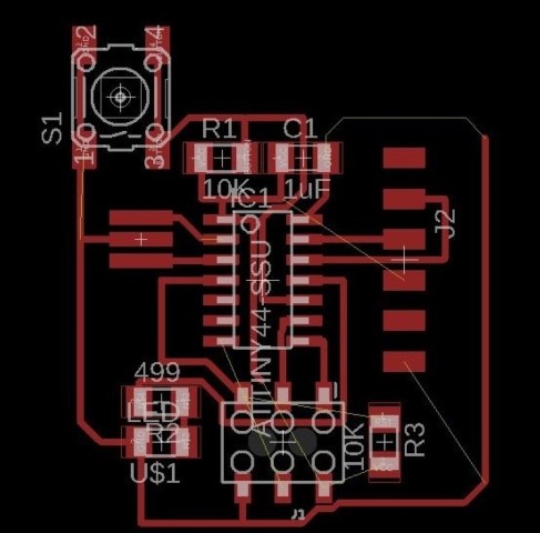
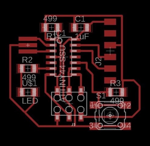
This is the final version.
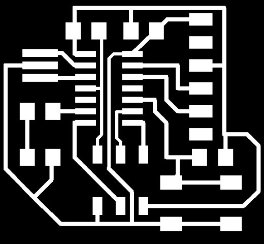

(Note that the pictures above are not the correct measures) You can download the pictures here: Board , Outline
Milling the board
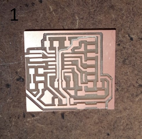
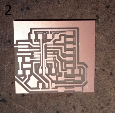
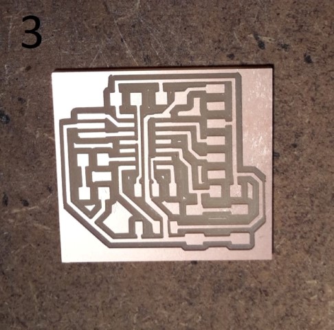
Then there was the problem with the outline.- I made a square in inkscape that was the same size as the outline of the “hello world” board. I milled this, but the square was a bit to small so it cut away some of the board.
- When I milled this I didn’t account for the origin of the board I just thought that if I made the square bigger, it would fit. So when it milled, it milled the outline way to close to the board and actually cut away some of the board which it also did with the first one.
Our copper plates are all kind of bend, so sometimes the plate has a hard time staying flat. I think that the plate were about to get loose from the bottom plate. This is why it is not proper milled trough. - Succes! I could have changed the origin of the “hello world” but instead I changed the origin of the outline. I moved it 2 mm to left and 2 mm down.

Soldering
The soldering went fine, I only had some troubles with turning the LED the right way. But I figured it out.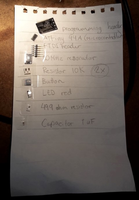
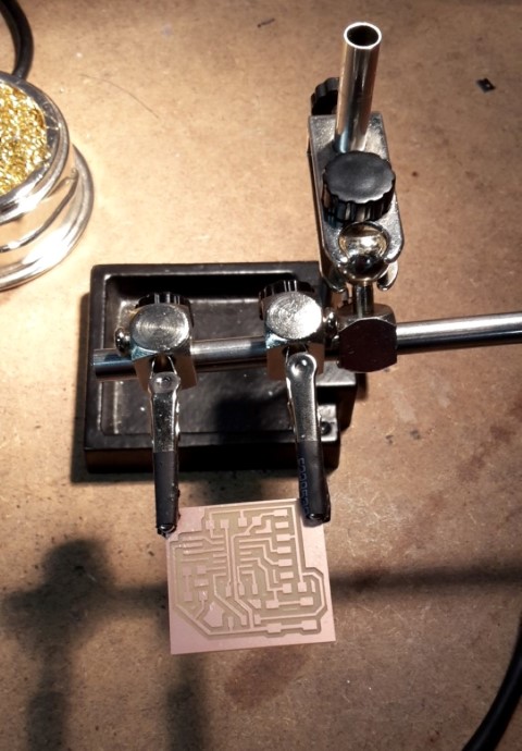
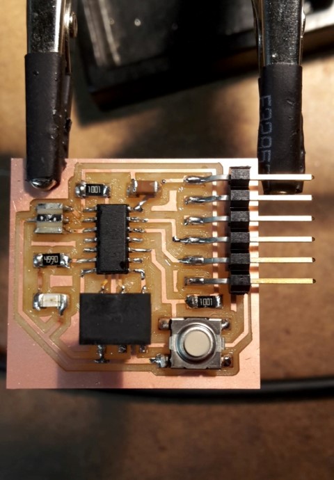
I tested my board with the multimeter to see if the solderings worked properly and to see if there were some places that were connected that shouldn’t be connected. But everything worked as it should.