3D Scanning and Printing
Assignment
- Design and 3D print object an that could not be made subtractively
- 3D scan an object
File
The design rules of the 3D printer
A part of the group assignment was to check the design rules of the 3D we have in the lab which is an Ultimaker 2. We were testing different parameters which we thought would be valuable knowledge for the use of the 3D printer. We have been testing the printers ability to print overhanging material with an arch test, it's ability make smooth edges on a small objects and its ability to make things non subtractively.
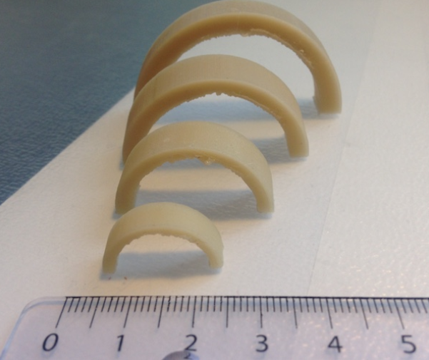
To test the printers ability to make overhanging material we made arches with an increasingly larger diameter until the printer would fail the test.
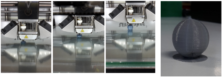
To test for the printer ability to make smooth edges, we made an increasingly smaller number of spheres.
Further down on this page is the documentation of making a locking mechanism which is also working as an example of the printers ability to make things which can't be made non subtractively.
What we learned from the test was that up till about 4 cm of overhanging material is acceptable, but decreasing the amount of material used, and therefore the weight, will possibly increase this number. The printer is also able to make smooth edges in fairly small sizes, but if you are only after an aesthetic point of view then don't go too small. Making things non subtractively is indeed possibly, but keep in mind not all edges will look as nice since support material is needed to support structures since the overhang is not endless as we also concluded.
Design and 3D print
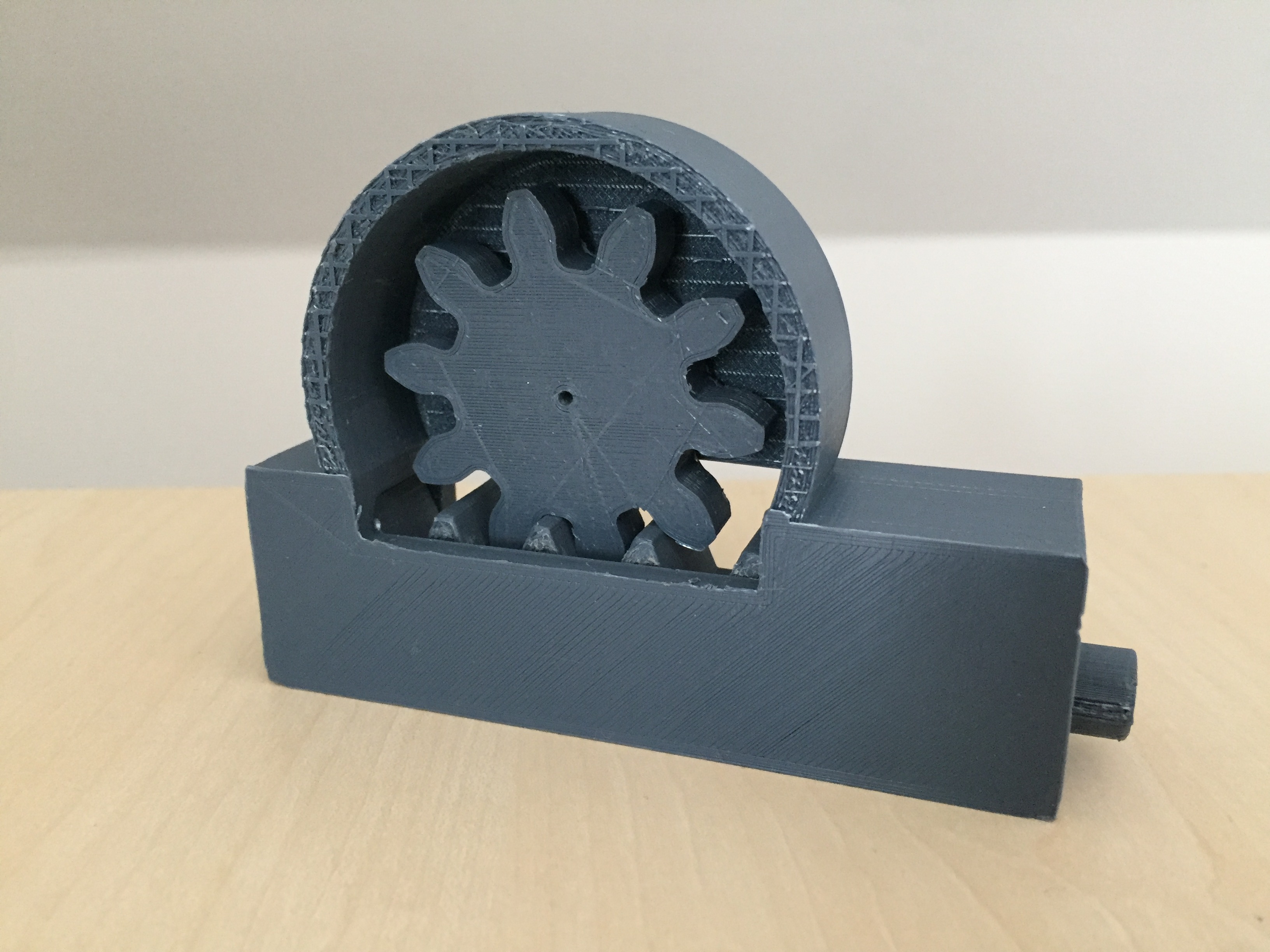
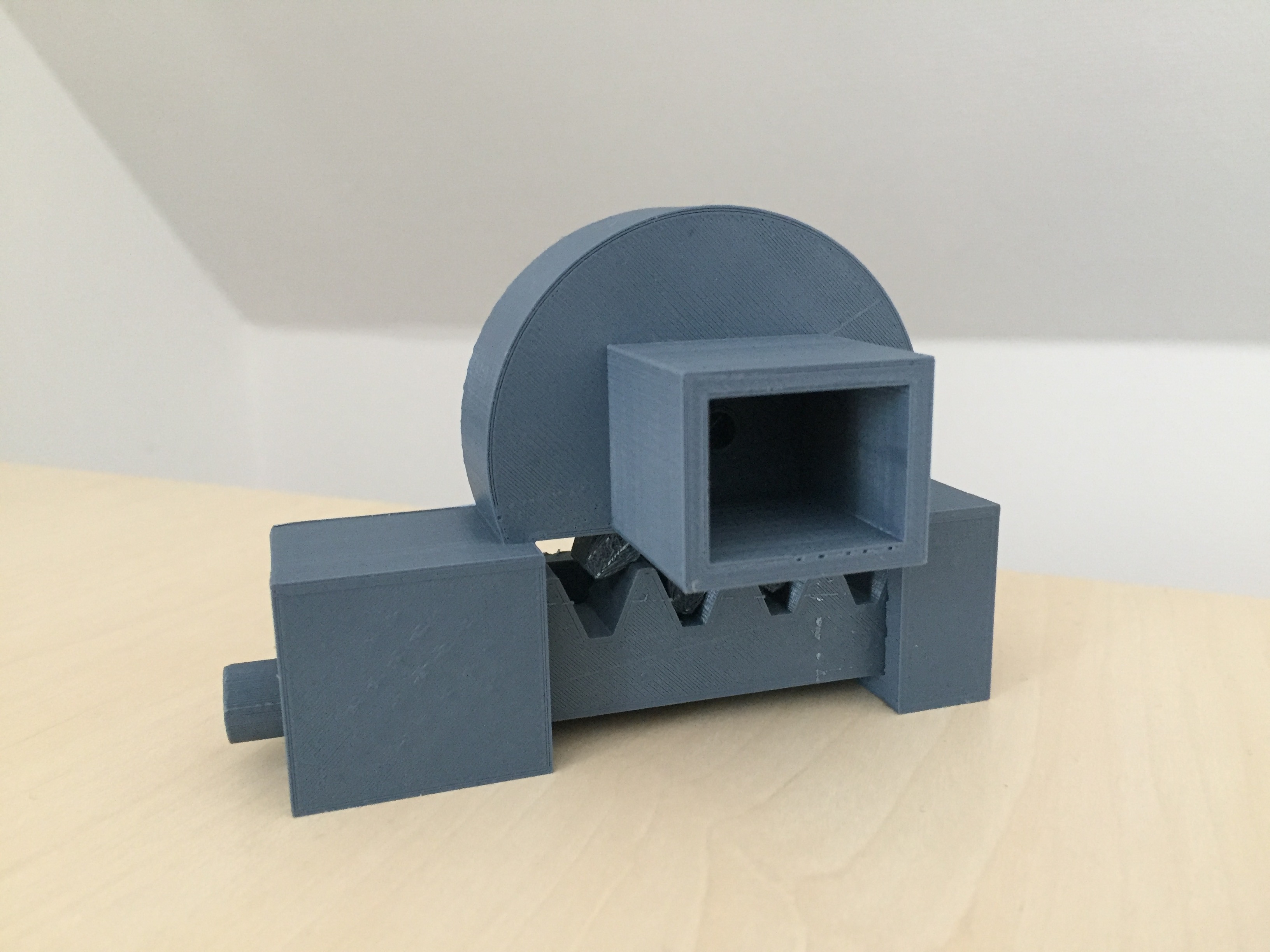
This was my secound experience with 3D moddeling to Computer-aided Design week to see the first experience. The object I chose to design for 3D printing was the locking mechanism for my final project. To see more about my final project, go to the "final project" tab. To find a design for my locking mechanism I googled various locking systems and decided to go for a rack and pinion design powered by a small motor. Only thing was that I would have to come up with some sort of box design so that the locking mechanism with the motor can mounted on a flat surface.
I used Fusion 360 to design my file and I found a video on the autodesk community showing how to generate a spur gear under the add-ins tab which I used to generate my spur gear. The video also gave some tips on how to make a pin that runs with the spur gear. The hardest part was to design the case that should be able to hold the pin, the spur gear and the motor without everything falling apart. Also the design should not compromise the ability to make changes and exchange the different parts once it has been installed, which made me realise that the design should not be too closed.
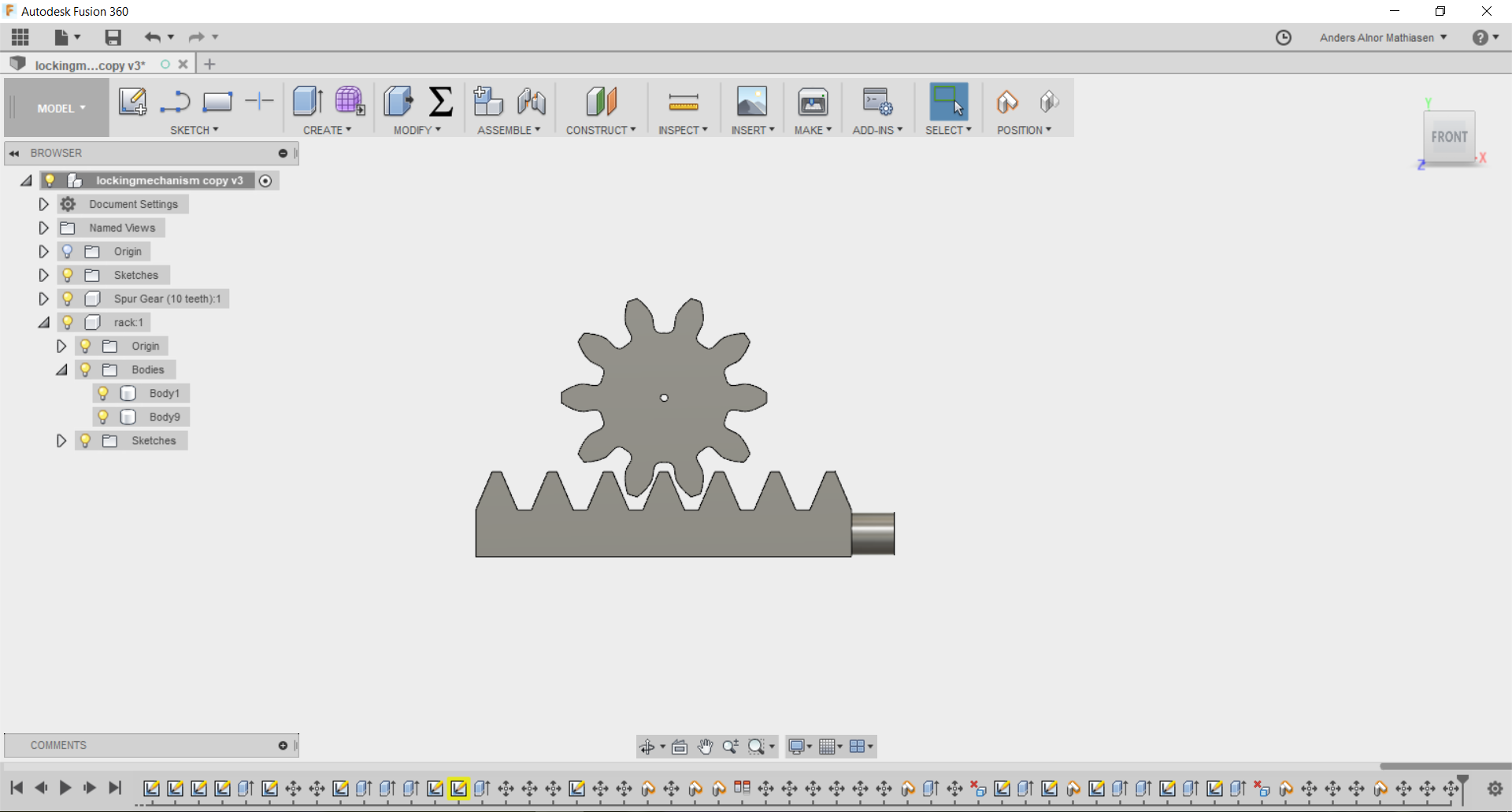
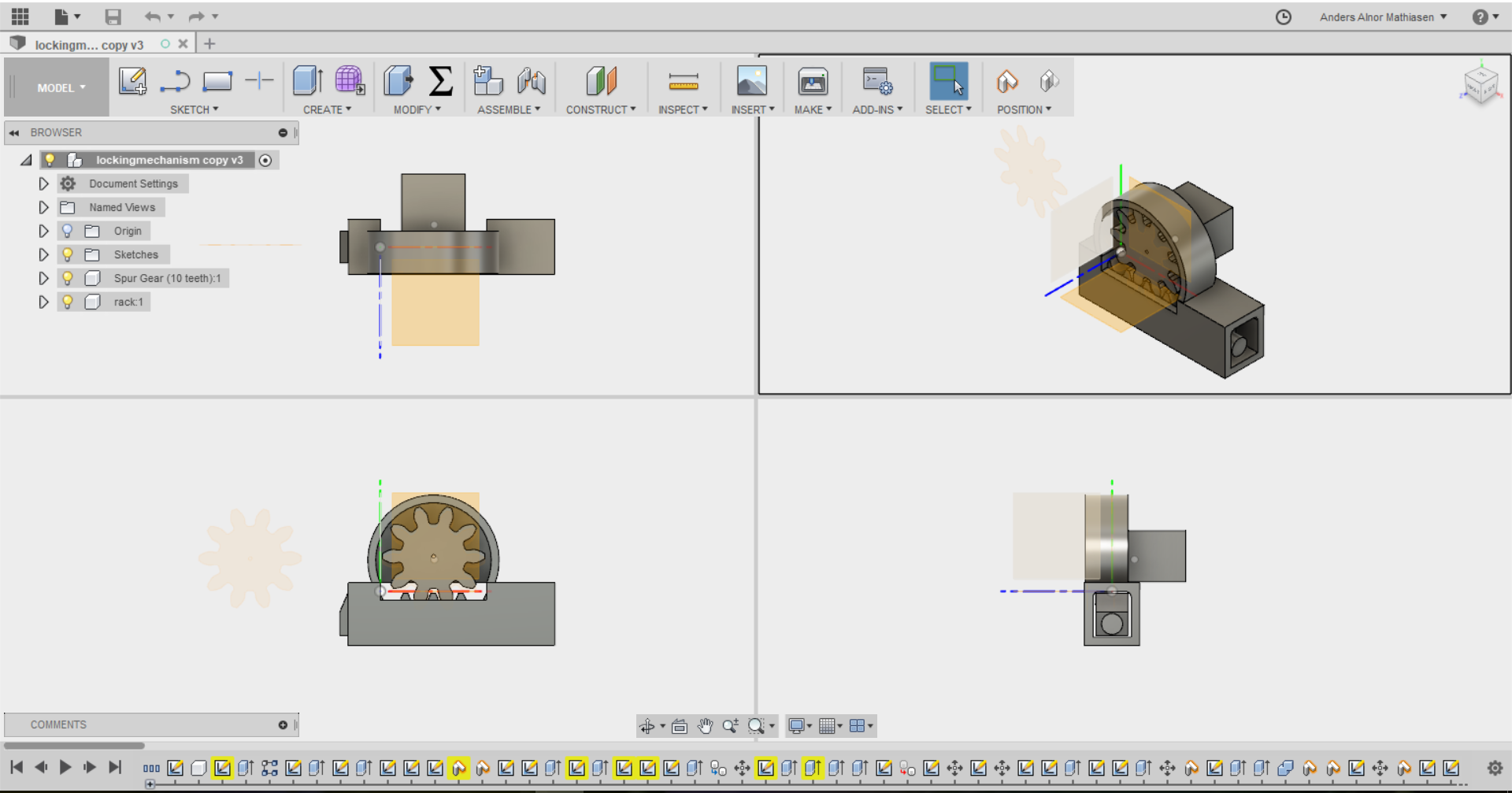
When exporting the file to a 3D printing software, in this case Cura, I had to decide whether to print each thing individually or print the design like every part were already assembled. Since the assignment was to make something that could not be made subtractively, the clear choice was to make everything at once as a assembled mechanism.
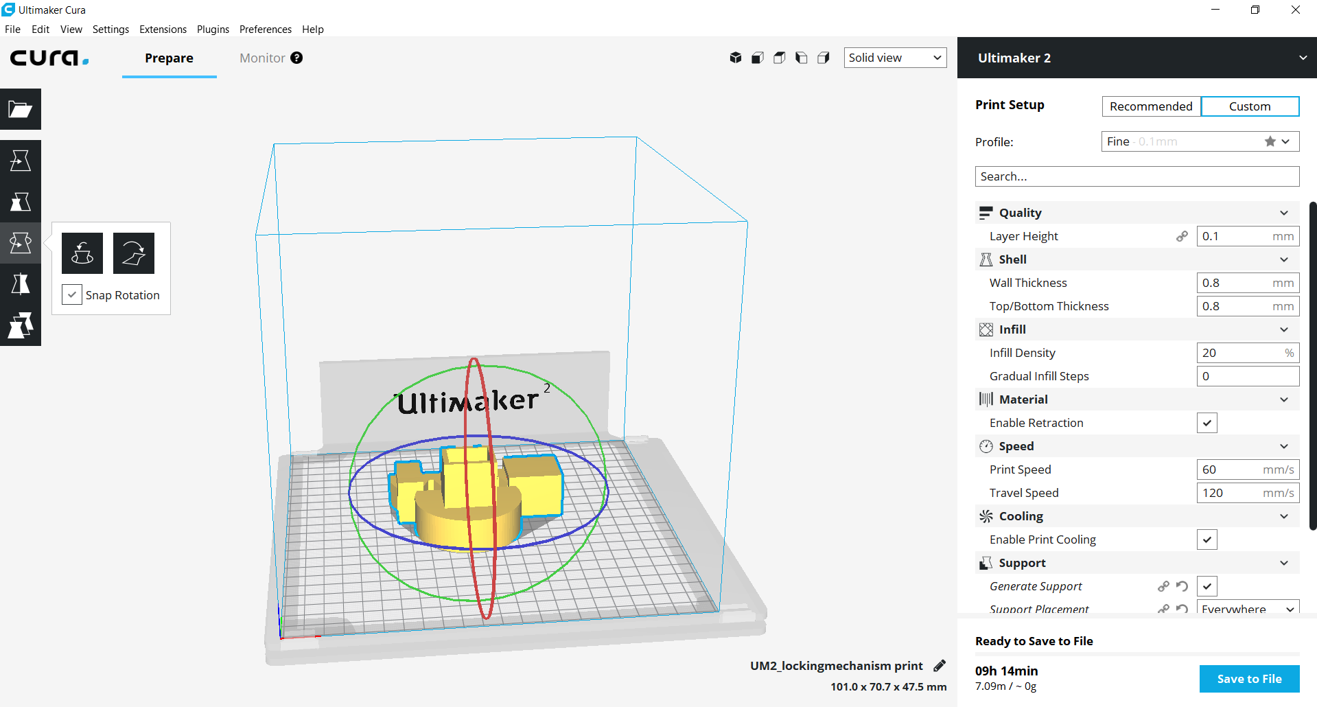
As you can see in the bottom left corner of the above picture, the print time was fairly high for this object. But it would have been higher if every part was printed individually because it would require a lot more support material.
The printer in action:
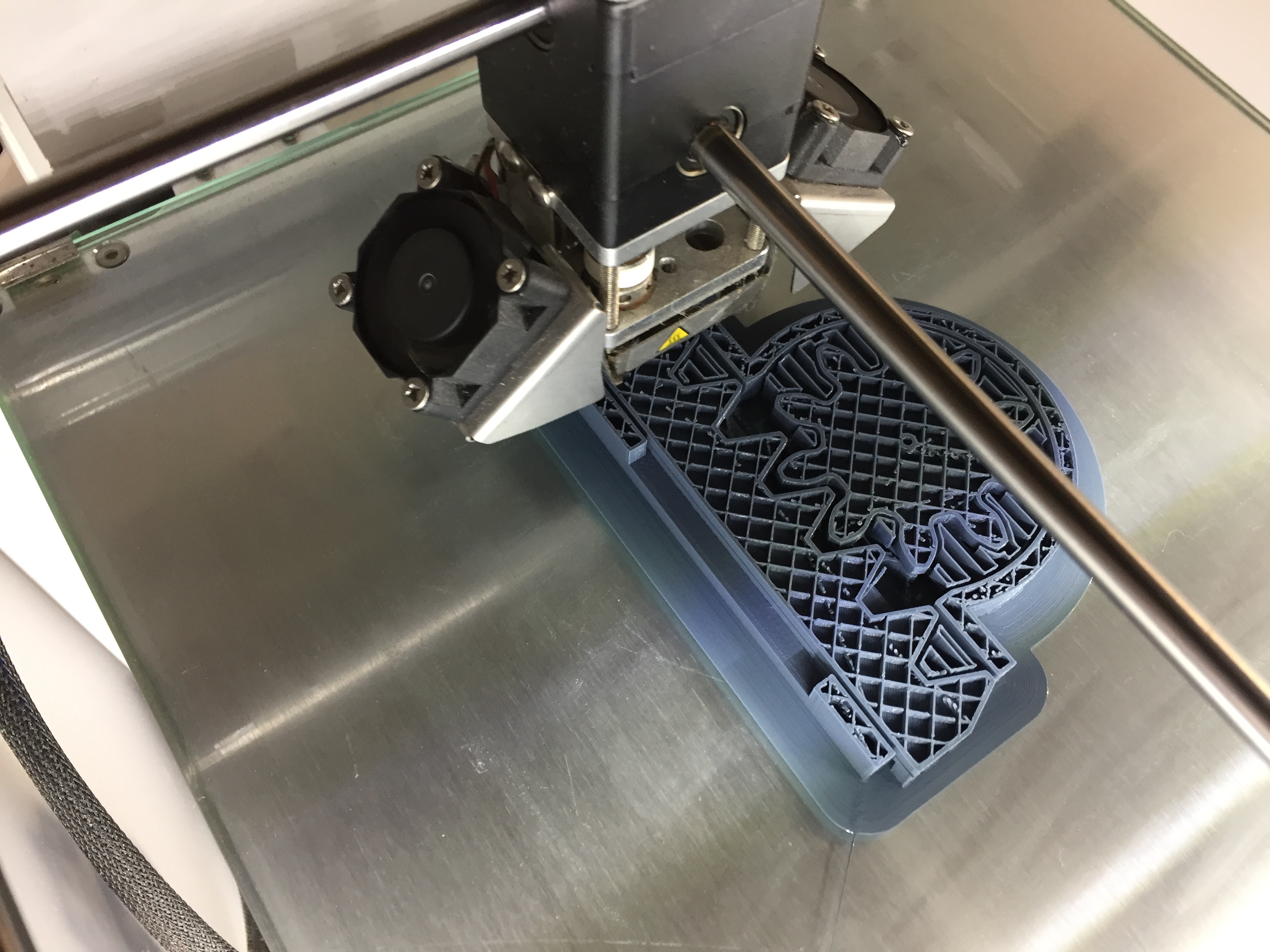
The fact that the spur gear and the rack was inside of the mounting device, made it a lot harder to remove the support material but I managed.
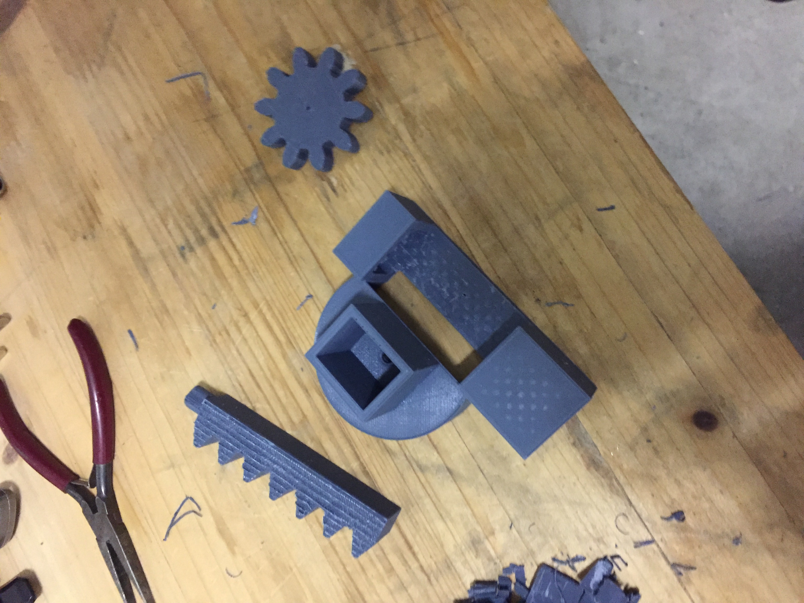
Before printing I was a little afraid that the spur gear and rack would not fit each other perfectly and therefore not be able to move. As far as I can see that is no problem, and the motor is also able fit very tightly in its hole. The only thing that does not fit is the tiny hole in the spur gear which is too small for the pin on the motor. This is something I believe I can fix with a very small bit for the drill which I will buy as soon as possible so that I can test the functionality of my design.
3D scanning
When 3D scanning we used an Ipad with a camera attachment. I wanted to 3D scan and print a cleat that goes under the cycling shoe when using clipless pedals since they are made of plastic and wear out quick if you are a frequent cyclist. Therefore It would be interesting if I could make cleats that were cheaper than the ones you buy in the store.
Before this week I did not know anything about contrasts when 3D scanning. I found out it meant it would be very hard to make detailed scans of black objects. Unfortunately the cleat I use, and also the only ones I could get my hands on during the week, are all black. My local instructor suggested me to cover the black object in a white powder. I found some flour that I used. Underneath you see the results with and without flour.
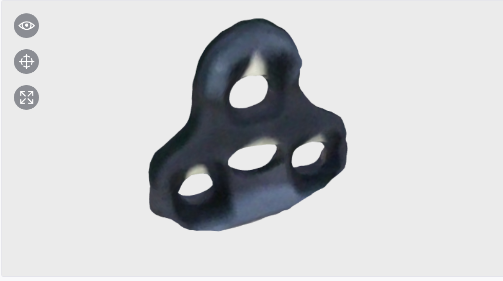
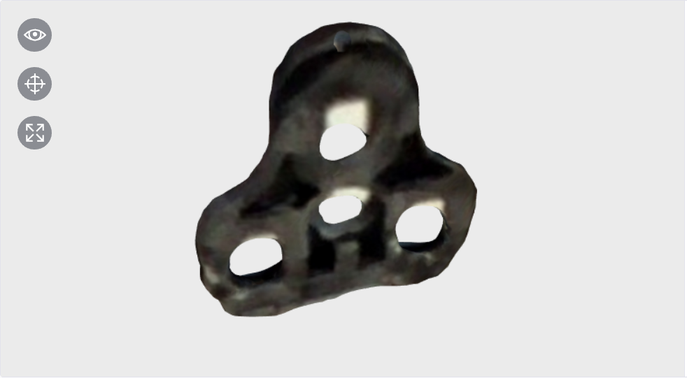
None of the scannings turned out well enough to make a 3D print that would be able to fit under a cycling shoe and click in a pedal.
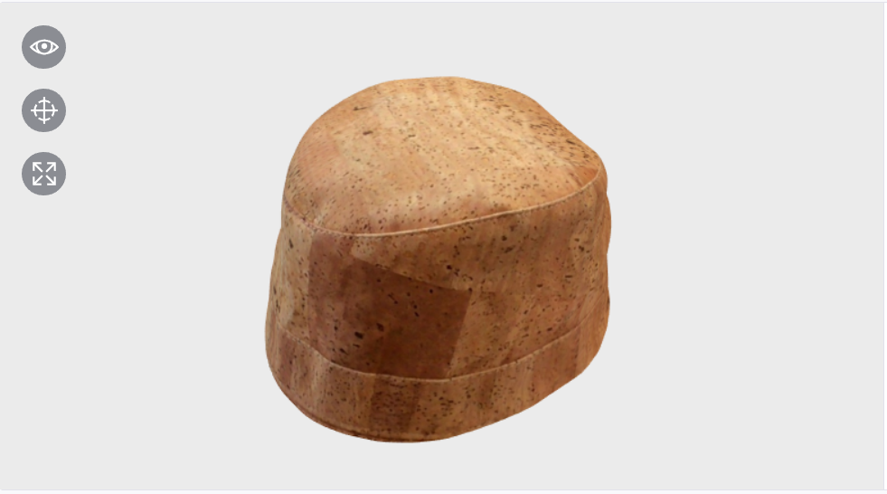
Since I didn't get the best results from the above scannings I decided to test the 3D scanning as a tool and found a hat made in cork. Underneath you can see the results of that scanning which shows that it can be a useful tool.