Electronics Production
Assignment
- Make an in-circuit programmer by doing printed circuit board milling (PCB)
Process
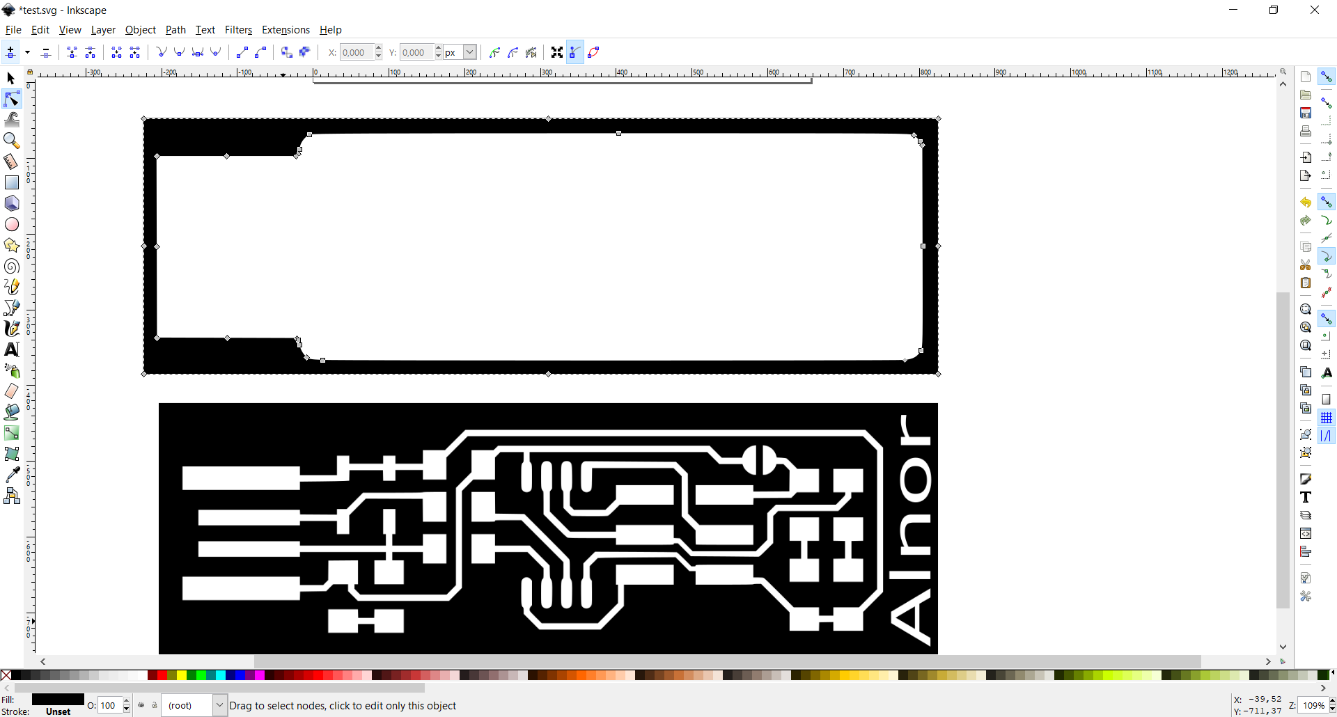
This week was all about making the first circuit board. We were not supposed to come up with the design of the circuit board ourselves, but choose from existing ones, and optionally adding something to the design. I chose the board made by "Brian" since he was good at explaining/documenting the process on his website. I did want to change something about the file Brian made since I wanted to add my name to the programmer so I would be able to differ it from the others laying around the lab. First thing I did was to open the default .png files in inkscape, where I would use the trace bitmap function to add the text and move the vectors in the picture for the text to fit. When working with circuit boards it's important to notice there is two files. One is the actual traces in the board and the other one is the outline. Therefore it was important to change both files/pictures for the text to fit.
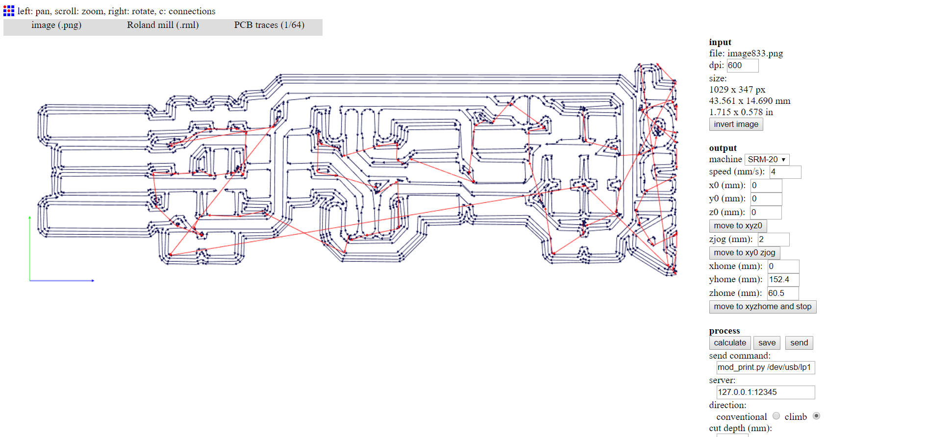
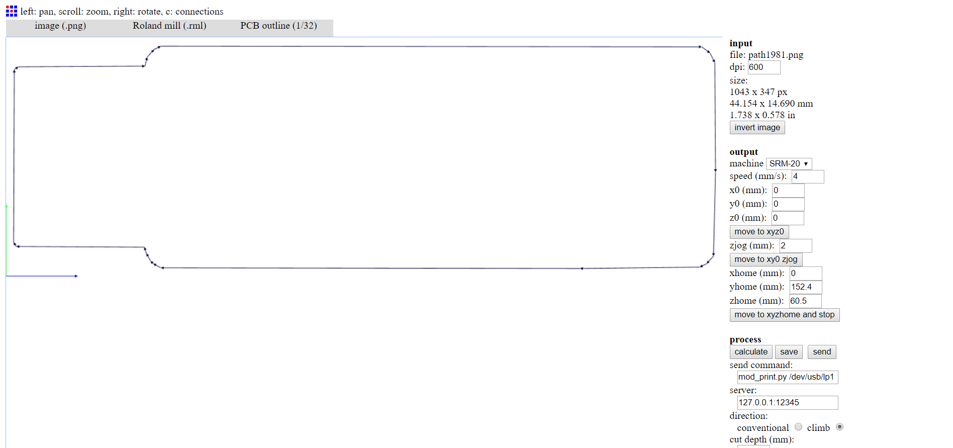
After the .png files was ready i used the website fabmodules.org to make a path for the milling machine to mill. The process in fab modules is to first select the file type roland mill (.rml) then PCB traces (1/64) when milling the traces and PCB outline (1/32) when milling the outline. In the menu to the left you should set dpi(make sure it's the same for the traces and the outline), the machine to SRM-20 and the height values to zero. After that press "calculate" and you will see the path the milling machine will be using. Also make sure that the number of offsets are enough. For traces it should be 4 to make the lines wide enough. For the outline 1 offset is enough.
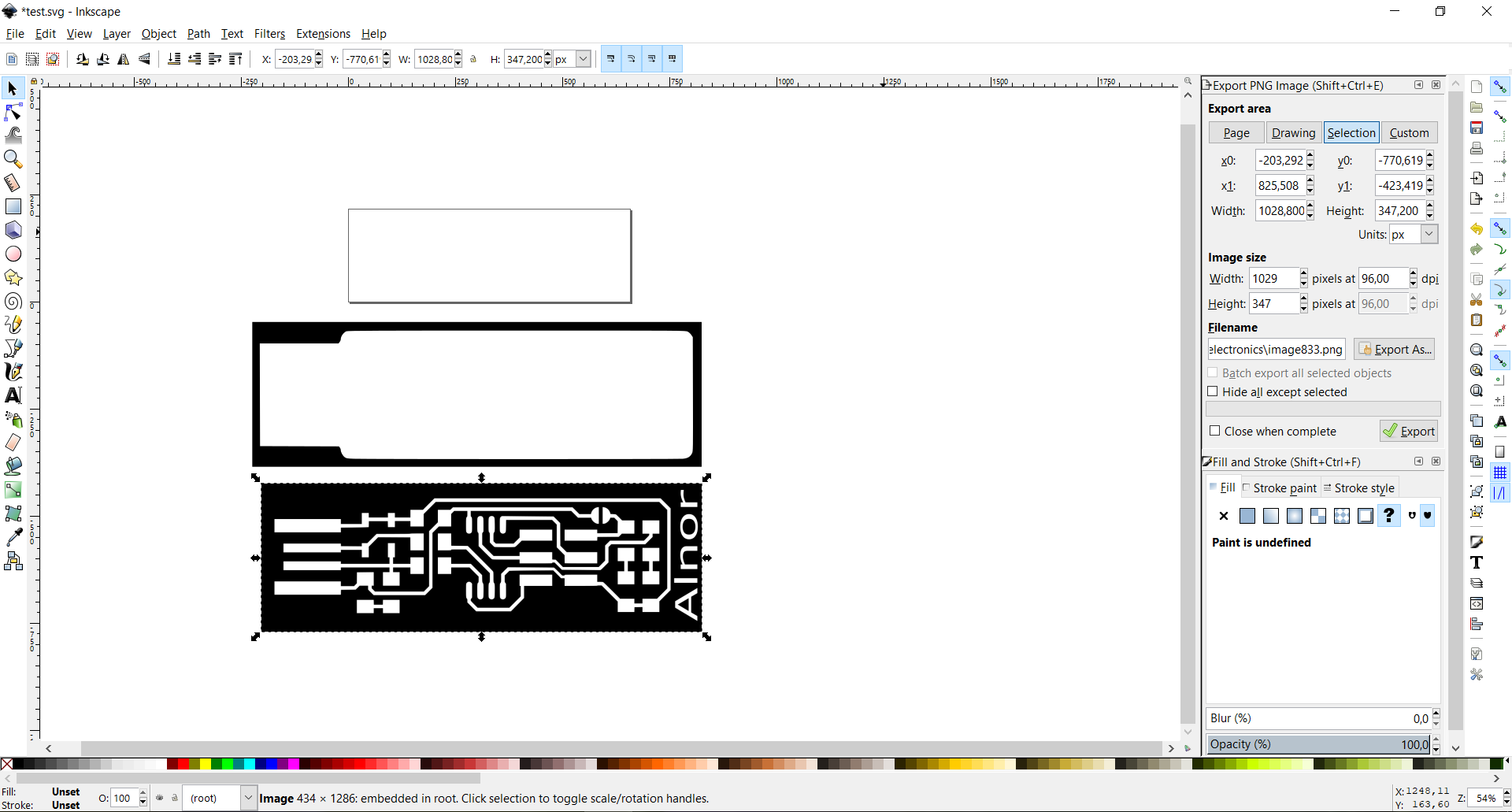
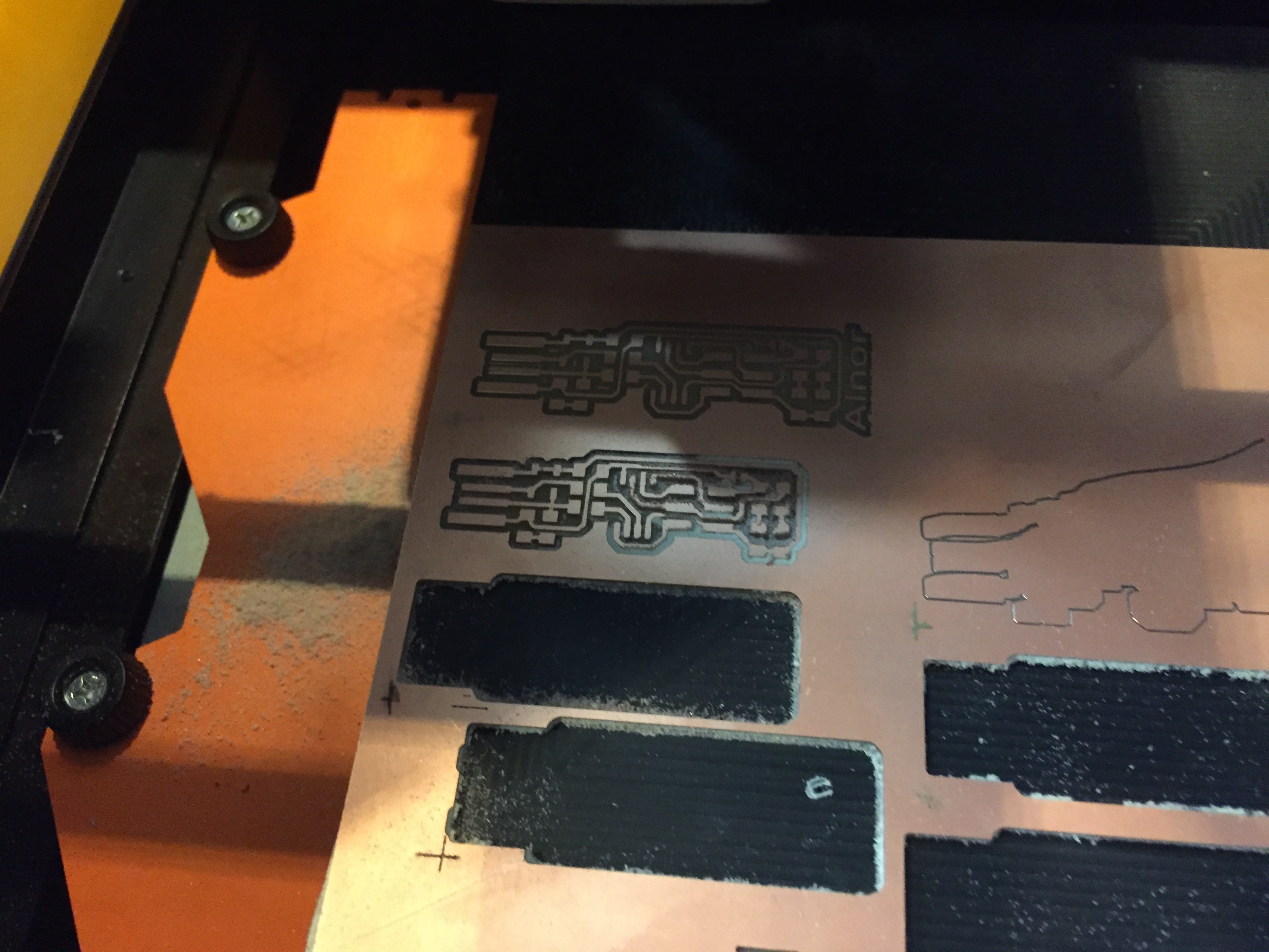
I had a problem matching the exact size of the treaces and outline which meant that the milling machine would cut into the traces when milling the outline which it is not supposed to at all. The first mistake I made was to not use the exact same dpi settings in fabmodules for both of the files. When this was sorted out It still did not match perfectly, until I realised that my settings when exporting the files as .png in Inkscape where different from the others in the lab who had no problems. It was the image size and pixels in Inkscape that had caused me the problems. Once it was figured out the files would have the correct size in fabmodules.
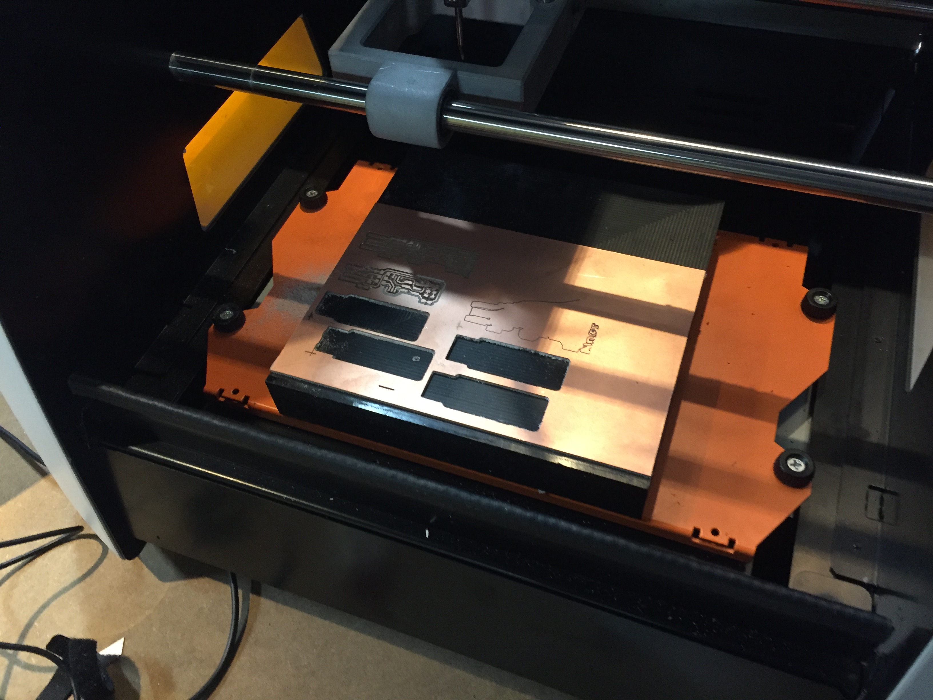
The files from fab modules is the one that should be used on the milling machine. When using the milling machine there is a few important steps to remember.
- First the copper plate should be safely secured with double sided tape
- The bit to mill the traces should be equipped
- The x/y height should be set according to the place you want to mill
- The z height should be set a few millimeters over the plate
- Loosen the bit until it touches the plate before screwing it in again
- Lock in the settings you have just made in the milling machine software
- Raise the z height a bit so it won't scratch the plate when you start milling
- Now press cut, delete any old files and select your own and the machine will begin
- Be ready to press pause if you see anything not going according to plan
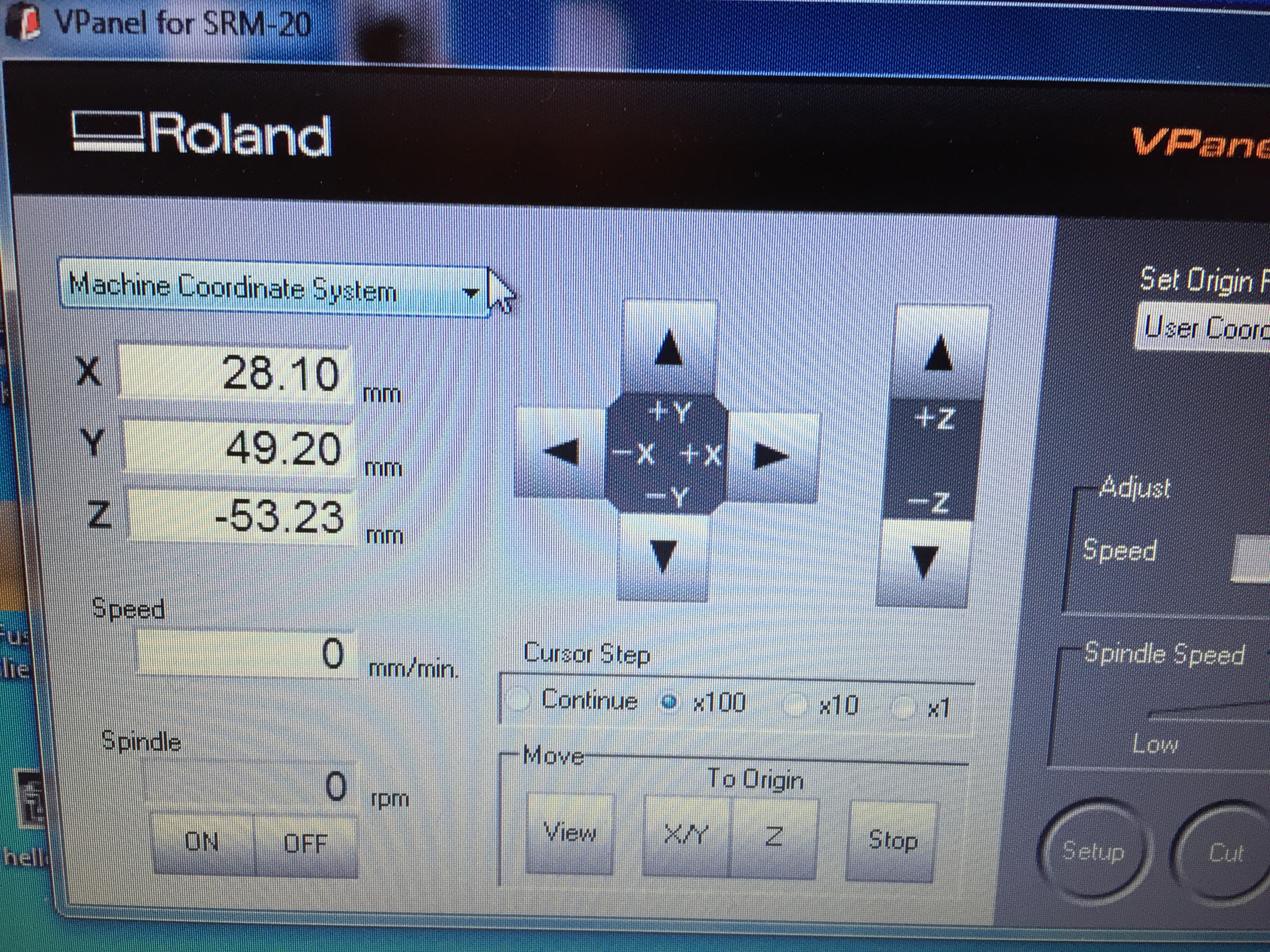
- Remember to take a picture of the machine coordinates so you can easily resume if anything goes wrong
After that you would want to do the exact same process with the file of the outline, but remember to change the bit into the other one (there is only two bits). When doing the outline you don't have to set the coordinates all over again, simply click "set to origin" since you have already locked them in when you did the traces. The same thing about raising the z height before milling still applies.
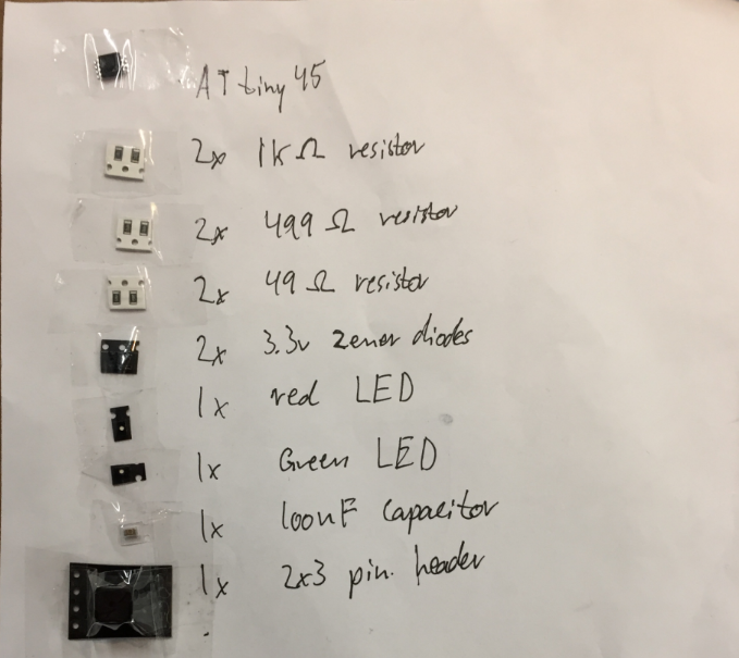
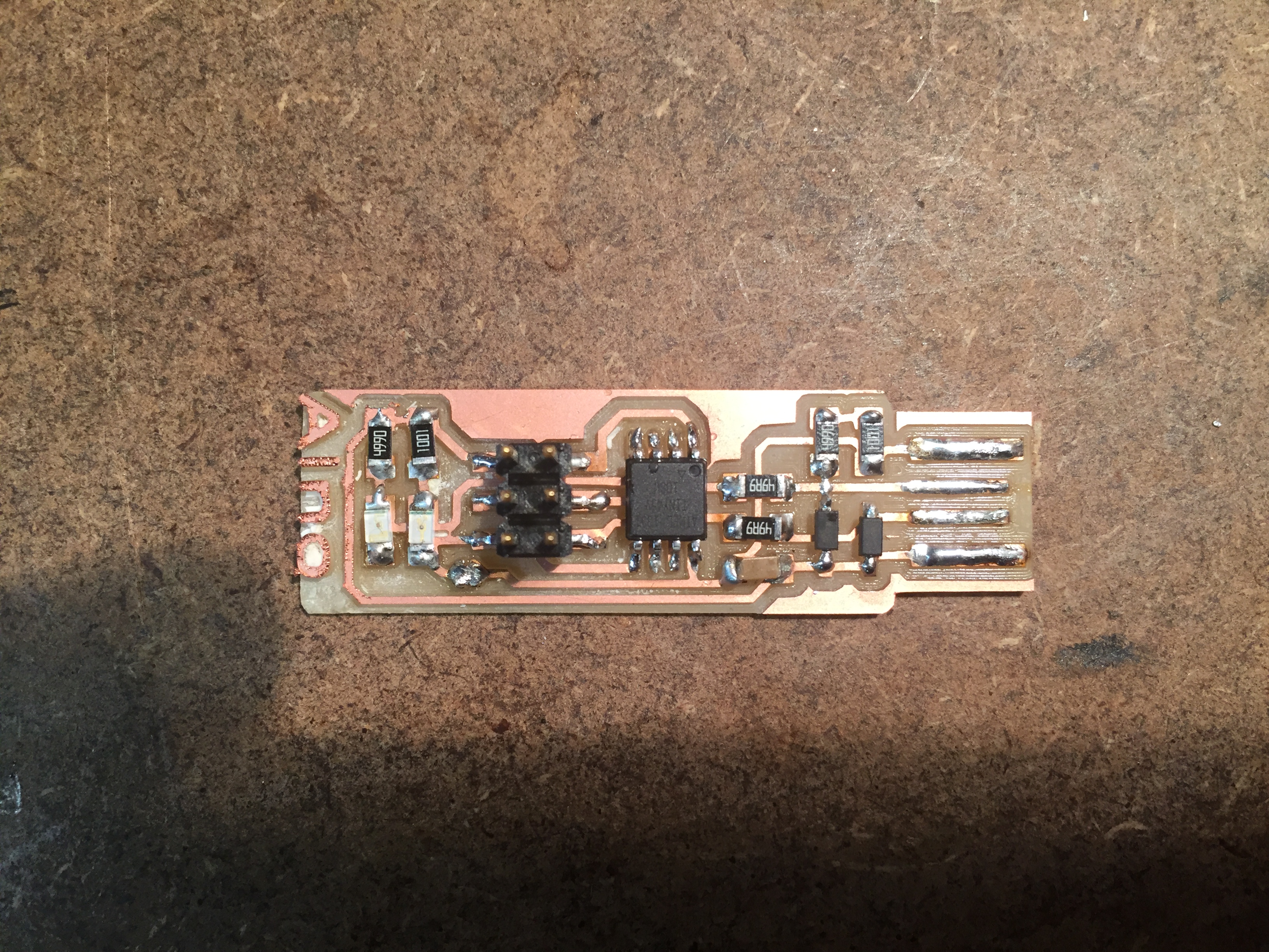
After the circuit board itself was made I found all the components that I had to use according to the information I got from Brian's website.
I had never tried to solder before, so my local instructor gave my an introduction and told me to try on some resistores before going to the real plate. I saw that when soldering it is crucial to turn the components the right way, for this design it was only a concern with the LEDs, the microcontroller and the two diodes. There is small lines or circles that shows which way they should turn. The difficult part about soldering was that all of the parts where so small, and the tip of the soldering station we had at my local fablab and at home where I finished soldering was big compared to these tiny components.
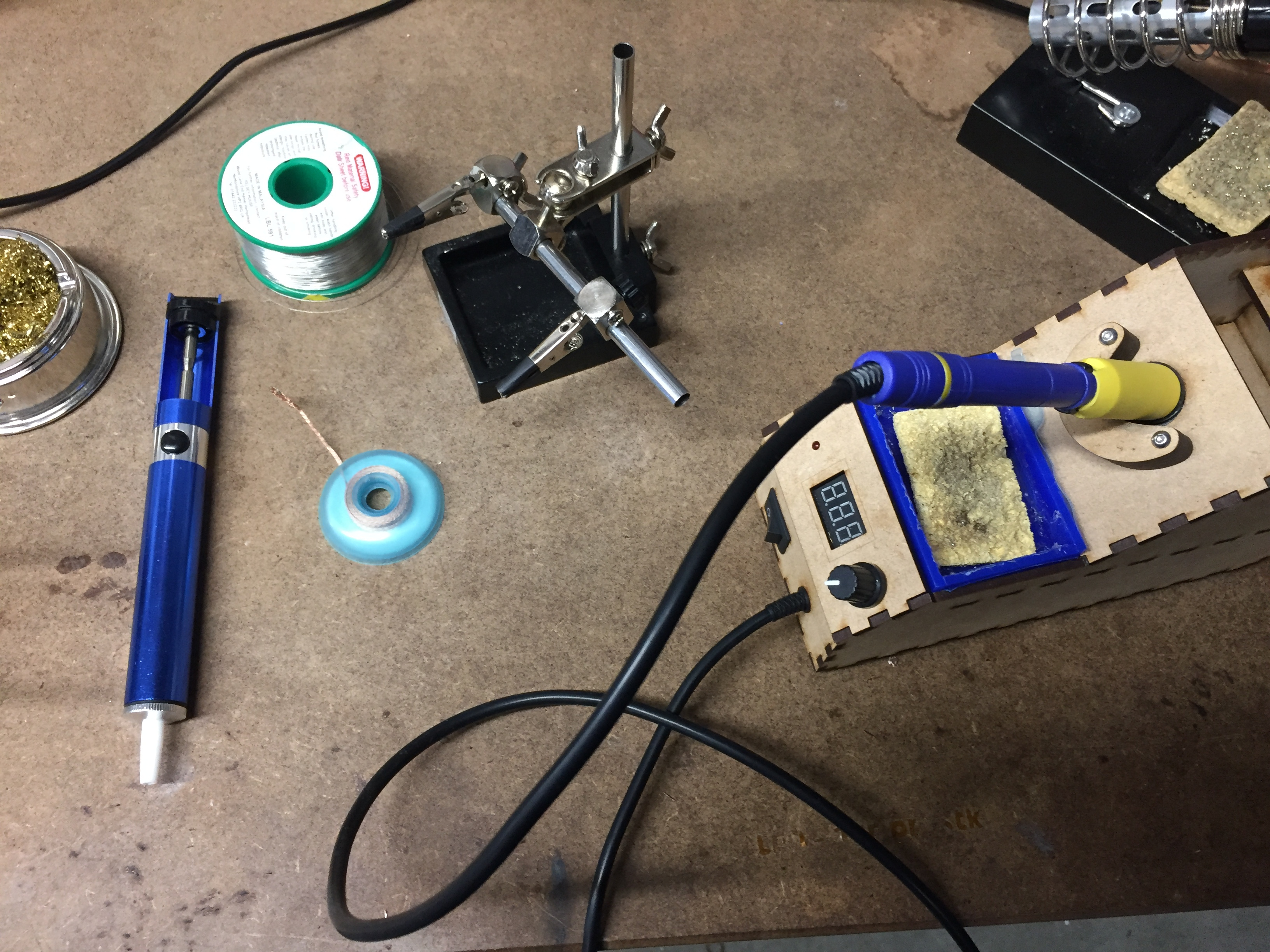
As seen in the above picture there is quite some tools that can be used when soldering. The pump and role of copper is for removing unvanted tin, and there is a stand for holding the PCB when soldering, while the other things a for keeping the bit of the solderingstation clean when soldering.
Debugging and programming
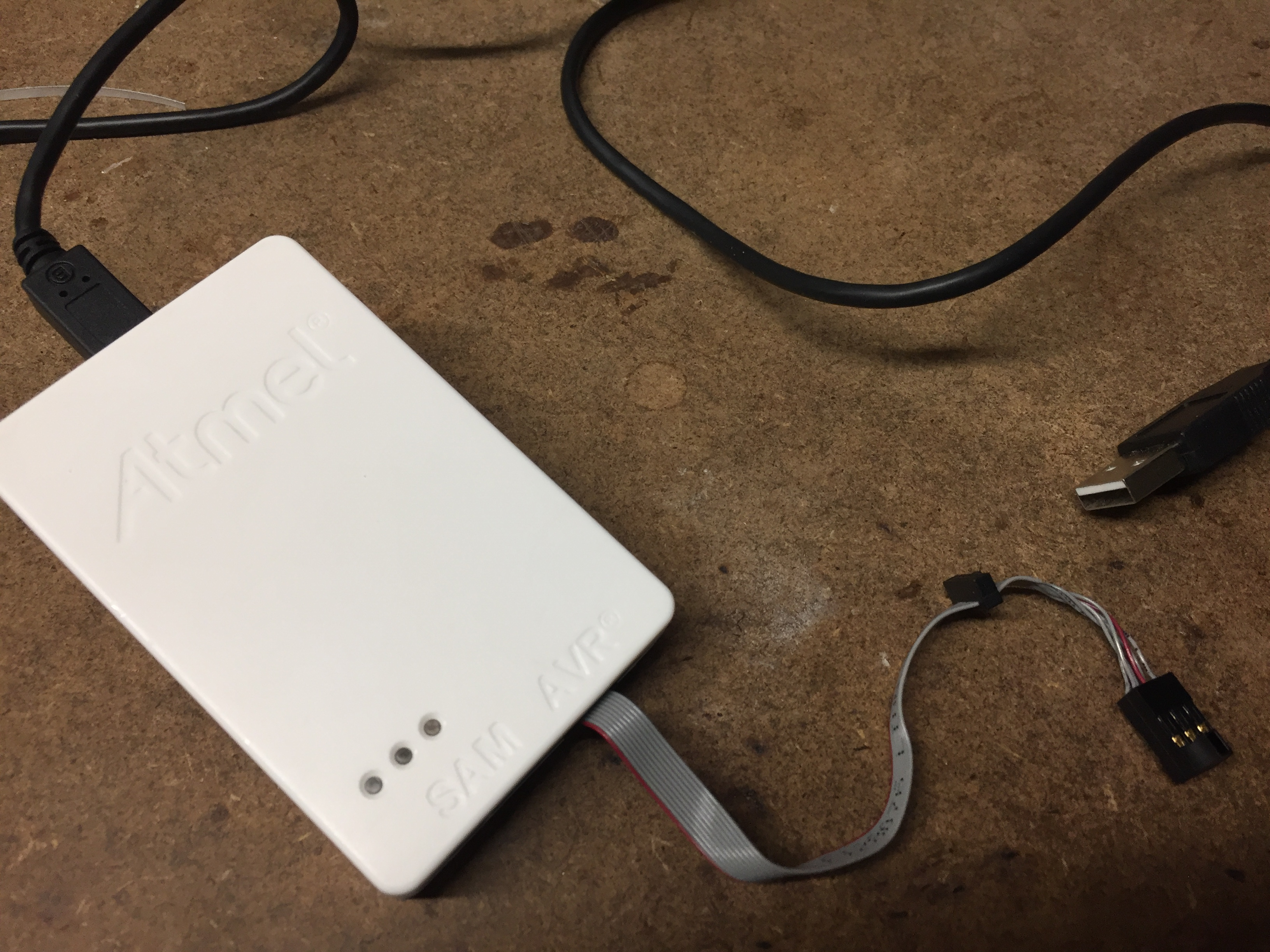
When I had to program the microcontroller on the circuit board I had to use another programmer. Since I haven't made one before I used a commercial one found in the lab, which was an Atmel Ice programmer.
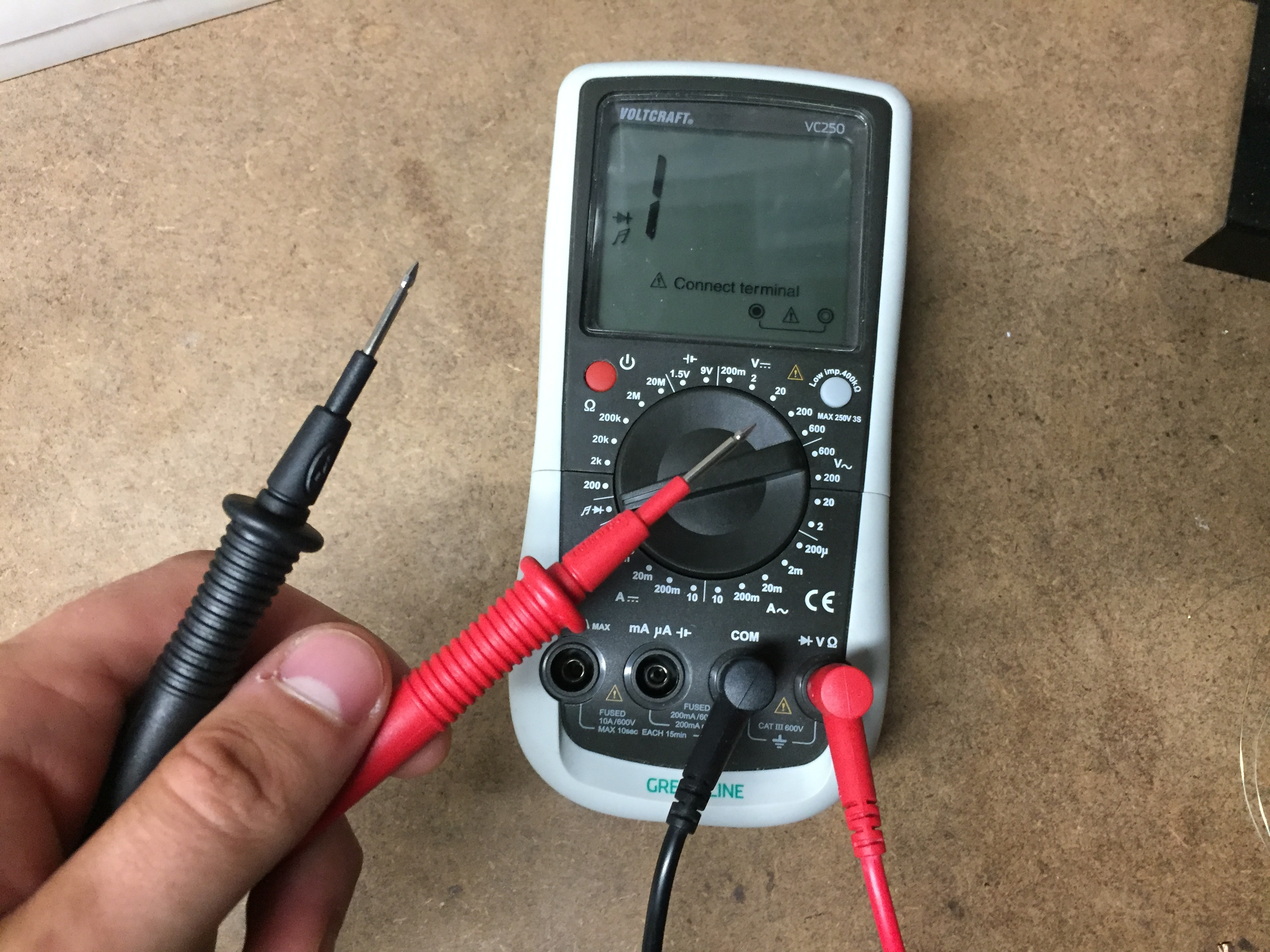
When I plugged everything it into my computer I saw that there was no LED lighting up as it was supossed to. To make it work I first tried to resolder the two LEDs and check with a multimeter for any loose connections. The multimeter was set up in a such way that it would give a sound if the current is passing through, which then indicated that the connection is good enough. This is perfect for checking for soldering errors. For example when checking for connection over a LED the red one should go to VCC and the black to GND, since it will send out a small current.
This method didn't solve the problem. My Instructor then discovered that under the LEDs there were three shortings since the milling machine did not cut enough of the copper away as it was supposed to do. I then had to remove some of my components, remove some copper with a knife, solder again and then it worked. With the issue solved and the Atmel Ice in my pocession there was only left to follow the intructions Brian made on his page about programming the micocontroller. This was done using Linux since we had an Ubuntu computer in the lab.
The final result turned out well even though the soldering could have been a bit more shiny, but I think this was a good result with the experience I had and the tools accessible.