Networking and Communications
Assignment
- Design and build a wired or wireless network connecting at least two processors
Files
Designing PCBs
For this week about networks between PCB's I decided to connect some of the boards I will be using for my final projects with a serial BUS. I therefore made a board which has an LED and button. From week 7 about electronics design I had the echo hello world board which already contains an LED and a Button.
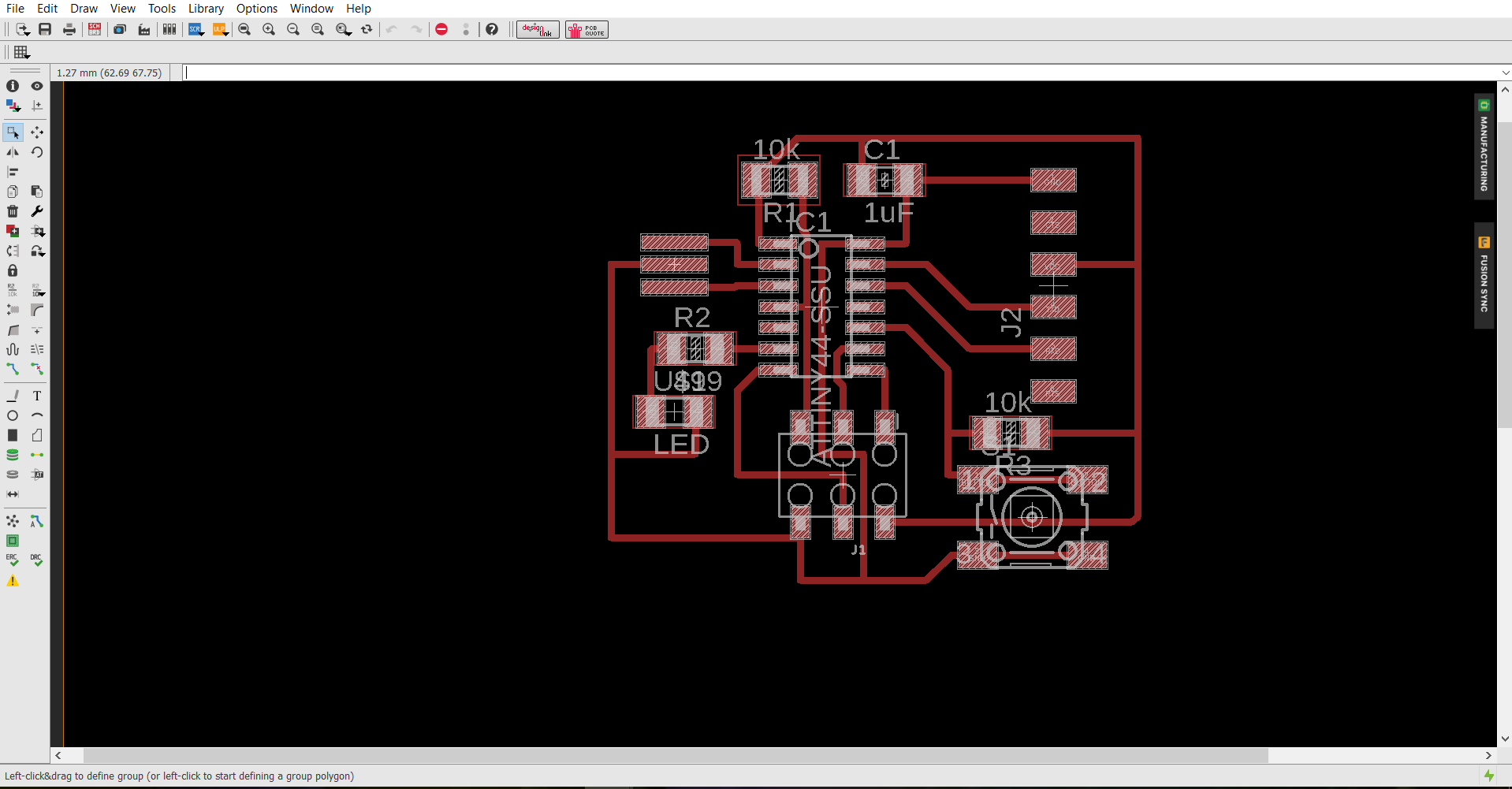
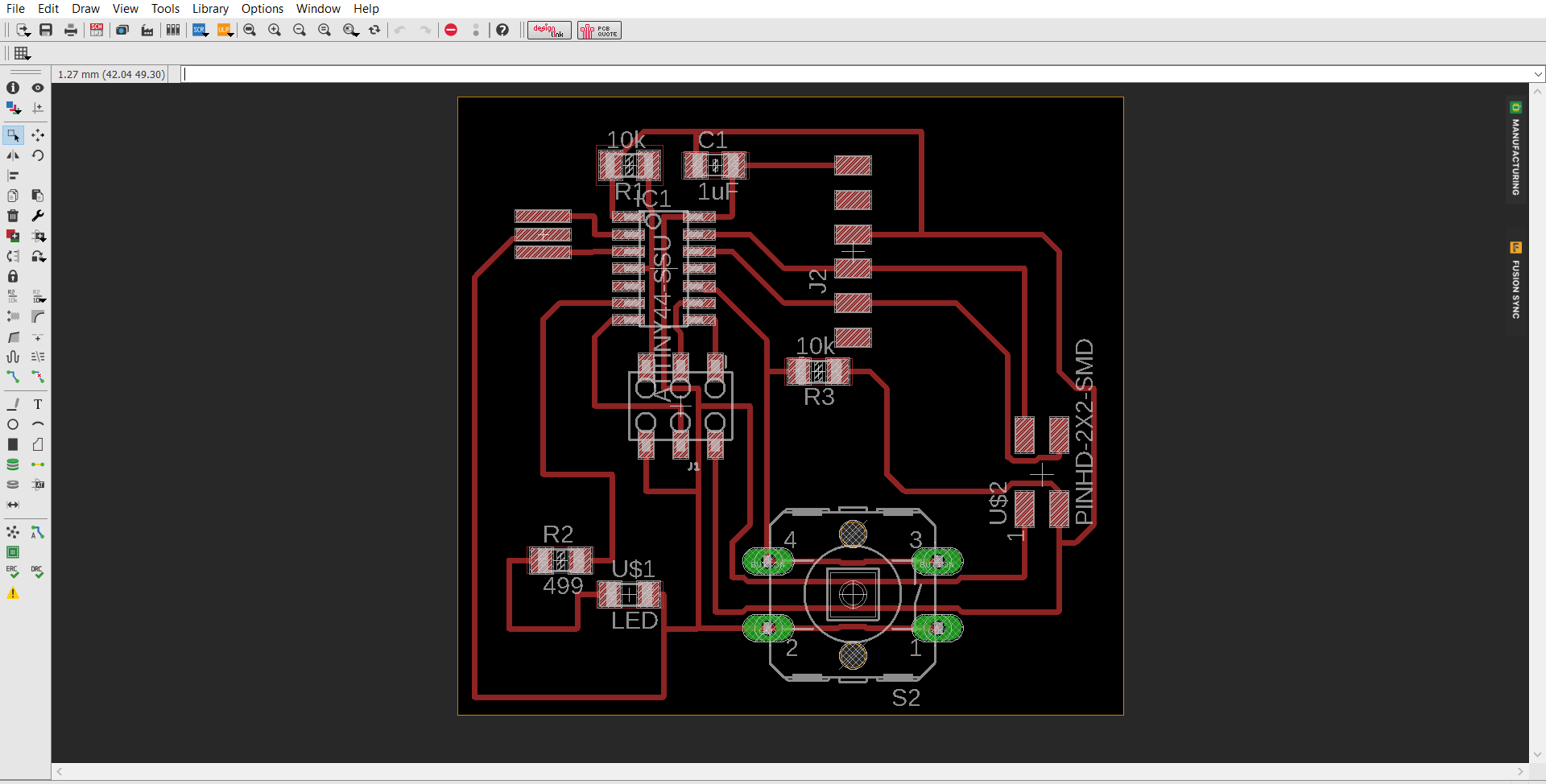
To change if for my needs I added a 2x2 pin header connecting Rx, Tx, GND and VCC which I will need for the serial BUS. I also found another button which was way greater in size compared to the usual small one. I found it in Eagles component library and swapped it with the original button. The pins of the button were meant to go through the copper plate which were done by adding small circles in the outline file so the milling machine would go all the way through the copper at these places.
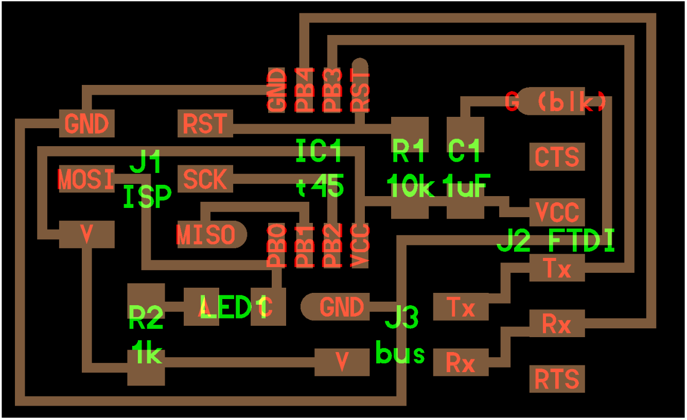
The other board I will be using is one of Neils example boards. I used the "master" one with a FTDI jumper.
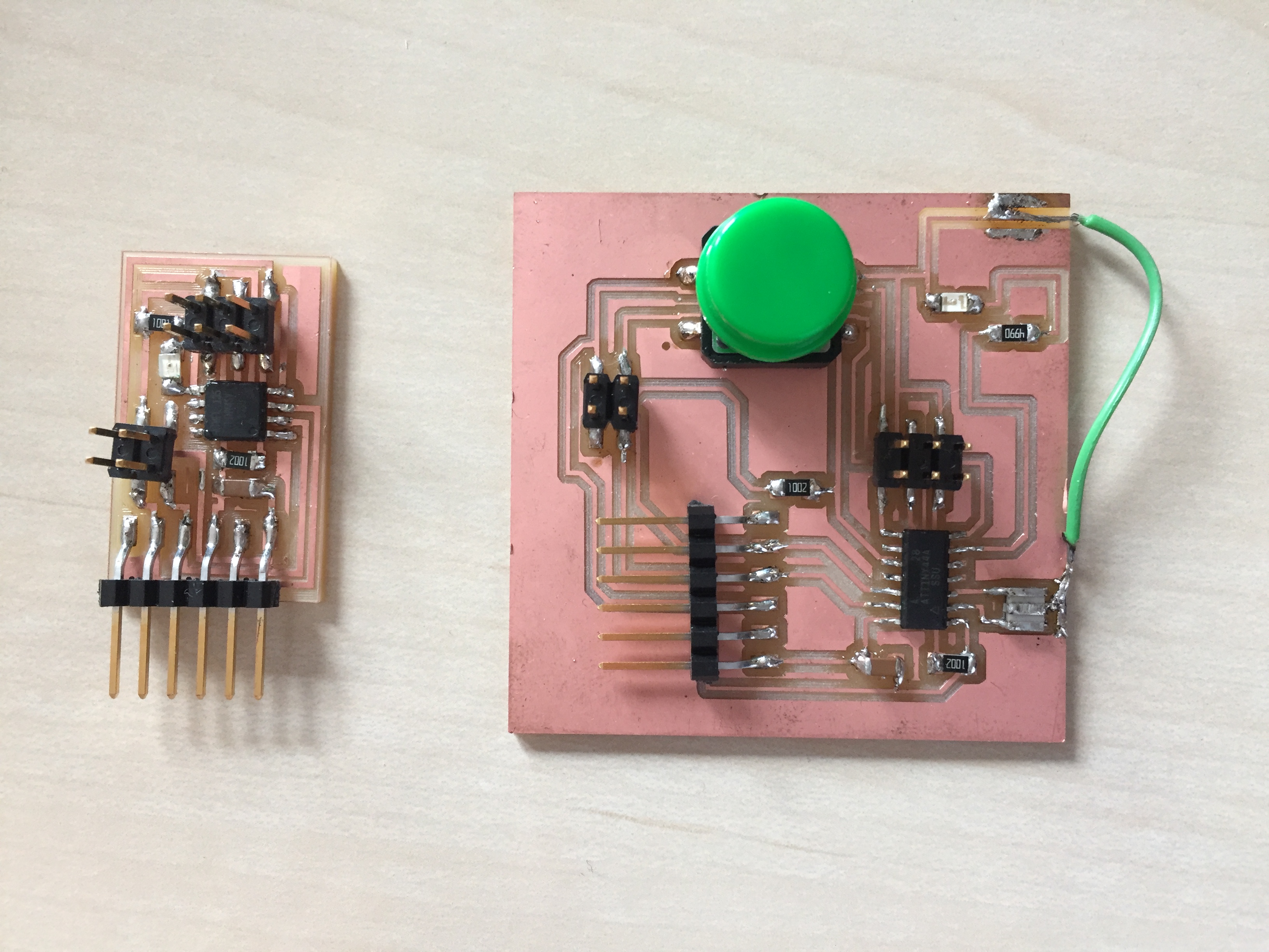
After having all of the files ready I milled and soldered everything. The outline file for the echo hello world board was not exact so I had to make a small fix with a wire.
Coding
When It came to coding I burned bootloader on a windows pc as always. After that I had to upload the c code. From experience I choose to do this on an Ubuntu computer. The first one I coced was the Neil example board. I chose to have this connected with the FTDI cable and be the master. I named it "0" in the code.
When trying to upload the code I got this mistake about missing separators. We have encountered this error before in the lab and therefore I knew it was about tabs in the code. After having deleted these tabs I tried again and it worked.
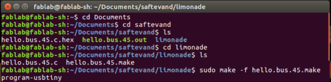
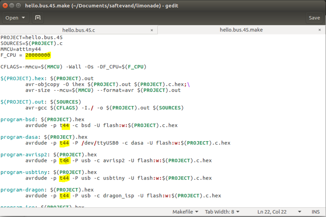
Next up was to upload the code onto my version of the echo hello world board. For this I would have to change the code since the code is made for a ATtiny45 microcontroller with an internal clock and I'm using a ATtiny44 microcontroller with a 20 MHz external clock. In the makefile I would change the clock speed from 8 MHz to 20 MHz and every time it said t45 I would make that a t44 instead.
In the actual c file I had to look at the different pin numbers and change them according to the ATtiny44. I did this by looking at the traces. I was seeing that the pins PB3 and PB4 where Tx and Rx in the code from looking at the example board. When referring it to the board I designed I saw that the correspondent pins were PA0 and PA1 and edited it in the c code. Same method applies to the LED pin. I also named this board "1".
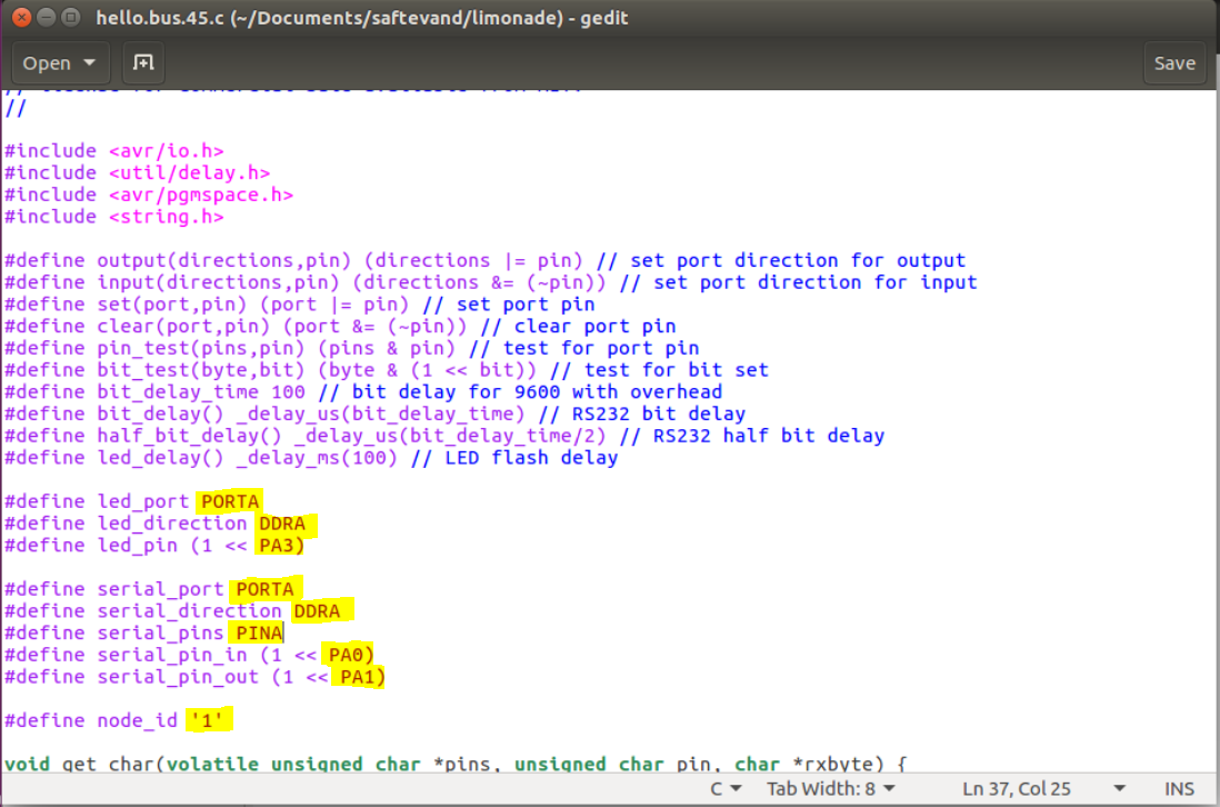
The first time I uploaded the code I tried to see if everything worked but I did not get a respond from the slave. I went back to the code and figured I would have to change the serial direction and port from B to A also, which showed to be the mistake.
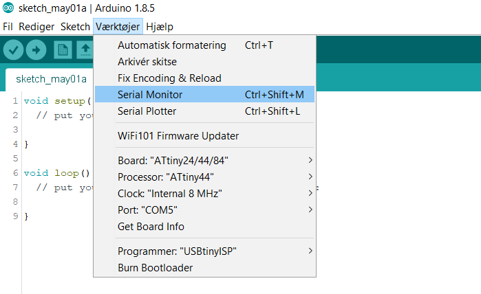
When everything was connected I was know able to communicate with both boards using the Arduino serial monitor.
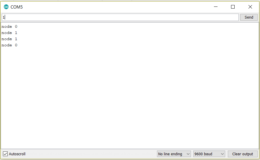
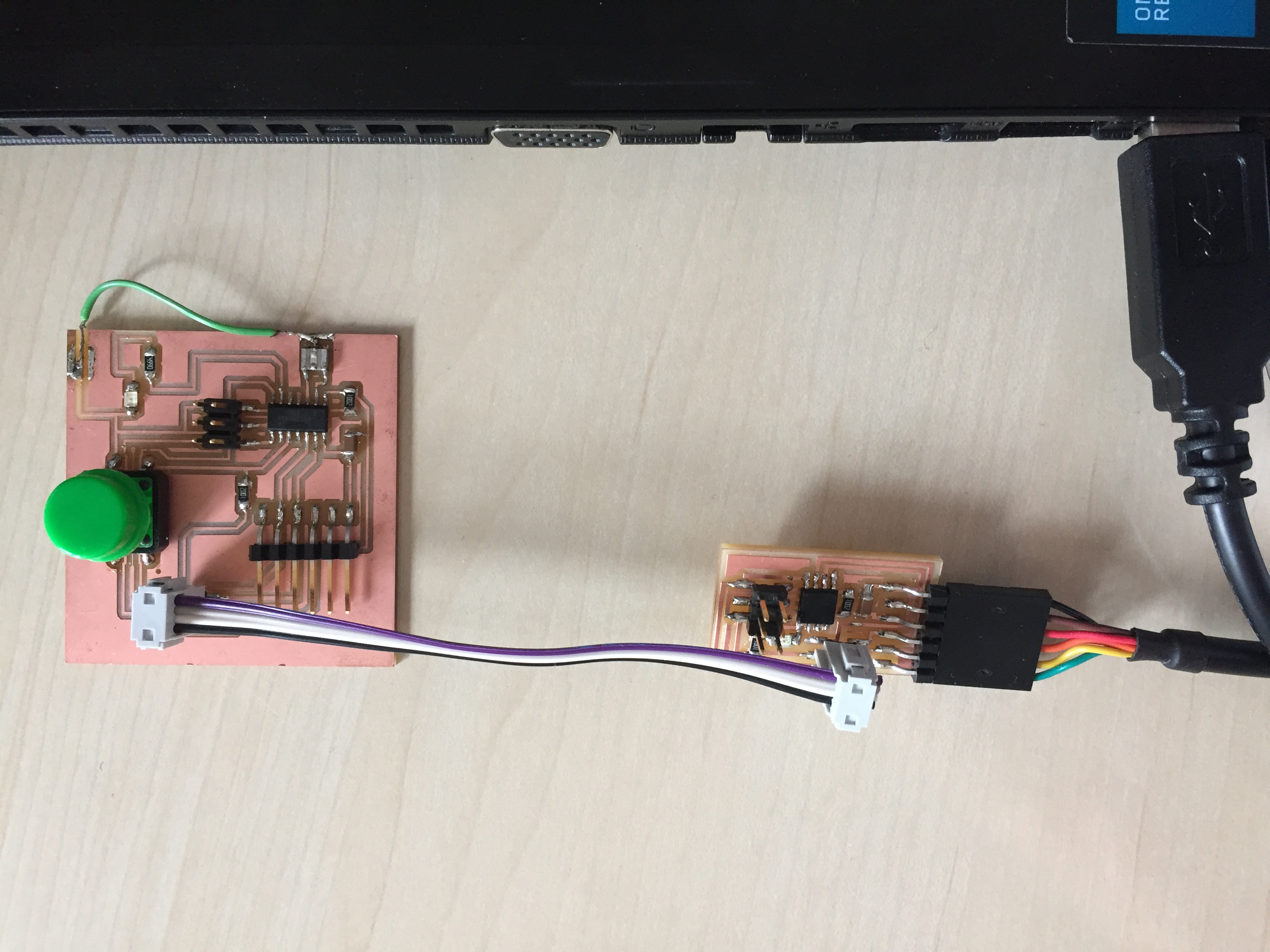
Underneath is a little video of it working. The button board looks a little different, which Is because I already started to modify it for my final project. The only difference is that the LED and button is attatched with wires