Molding and Casting
Assignment
- Design a 3D mold around the stock and tooling that you'll be using, machine it, and use it to cast parts
File
3D design
When deciding what I should make for the molding and casting week I looked at my final project and started to think about what I needed. Even though I had already made a locking mechanism with a gear in it, molding and casting would be another great method of making gears. Also it could be fun to compare the quality of the 3D printed gear I made in week 6 to one made with casting and molding. My instructor gave me a link to another student who had been successful making gears. The gears he showed me was made by Kevin Cheng in Fab Academy 2016. I looked at his website for inspiration and tried to figure out if I could improve anything. The one thing I noticed was that not all of the teeth in his gears was fulfilled with material. To me it looked like there was some air that was not able to escape. Therefore I was adding more holes for air in my design. I also made the pins that was going to hold everything together with flat edges instead of round, something I saw others had been successful with.
When designing the 3D model I generated the gear with an add-in in Fusion 360 to fit the size of the locking mechanism. I added some pins that would hold everything together when casting, a place to poor liquid into and some air vents.
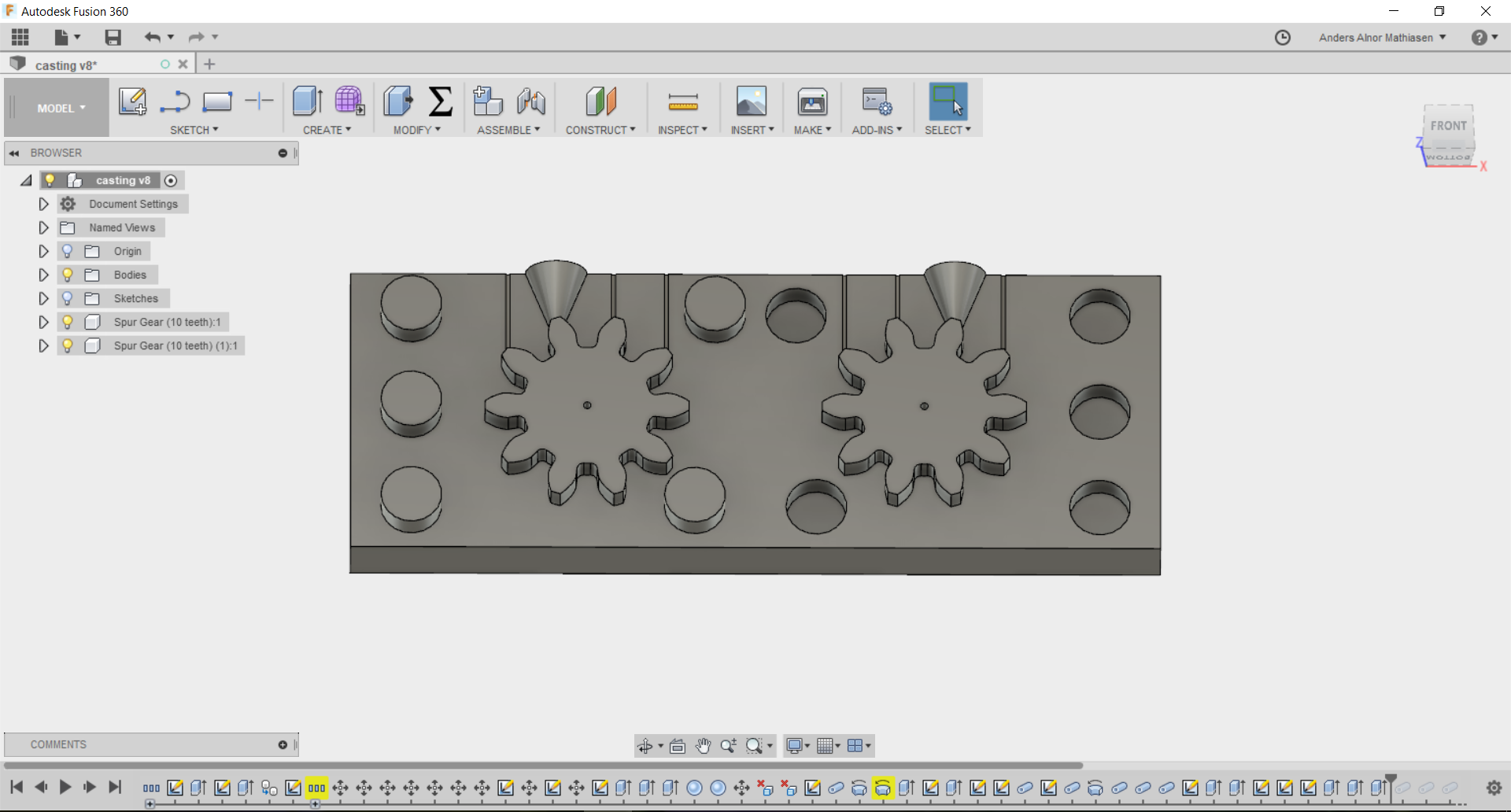
When doing molding and casting you have to think about designing the positive model, then making a negative form that you will put your liquid material into so it once again will be the positive version. This was something I had to think about a lot when designing my model. Once I had to machine the design I made I realised that the air vents was made wrong. On the picture you see the air vents are made as canals but they were supposed to be extruded outwards instead. This was changed on the computer connected to the CNC machine.
Machining
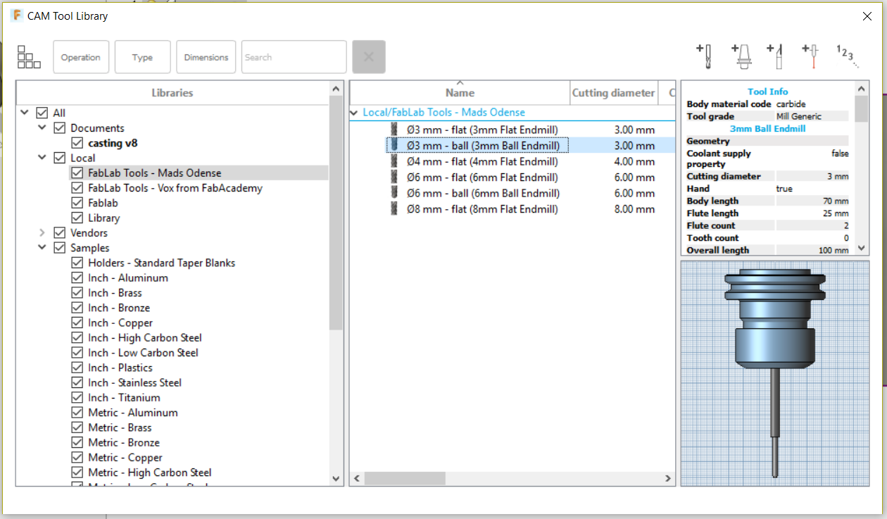
Because of an accident we had some weeks ago mentioned in Computer-controlled Cutting week, we used a CNC shopbot machine in a nearby city again. Last time we used the software VcarvePro to design the file for the machine to use. This time we used the cam function in Fusion 360 instead. The first thing to do was to add the settings about the different drilling bits we used with the machine under manage and tool library.
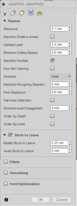
After that it was possible to create a path with the desired bit. The guy in charge of the machine decided it was not necessary to use a big bit to get rid of the rough part first. Under 2D and 3D in the top menu, we were able to select the kind of path we would be using. In here there is a lot of settings to play with. Some of the most important is to set the speed you will be drilling with, make sure the direction of the z-axis is set correct. You can also select the type of ramp you will be using (the degree which the bit will go into the material), but this is not necessary when drilling in soft material. Since we are using a fairly small bit and only doing one pass, there is no need to having stock to leave which you can also set in these settings.
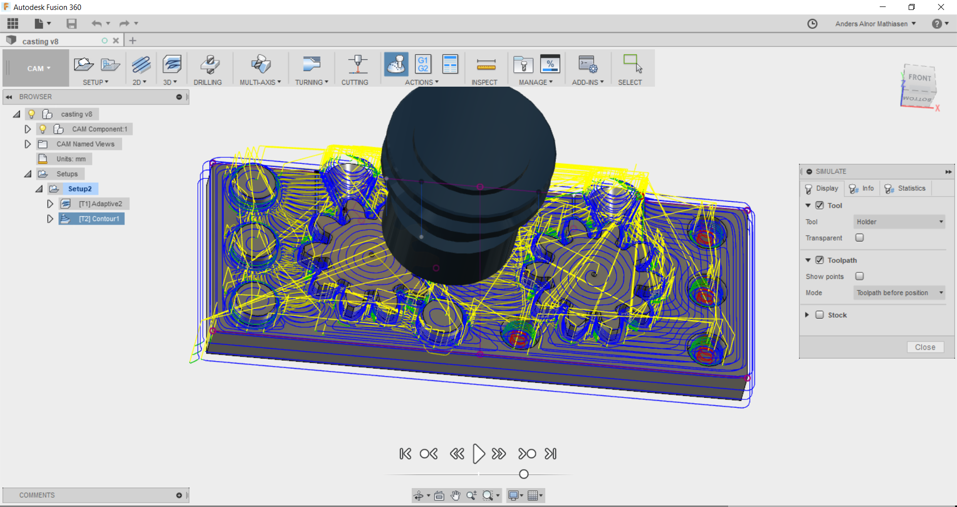
After everything is set, we pressed right click on the setup we made and pressed simulate to see if everything worked according to plan. Note that the settings you I is not the ones displayed in the pictures, since the path was made on a computer connected to the CNC machine.
After having confirmed the simulation it was time to machine the design.
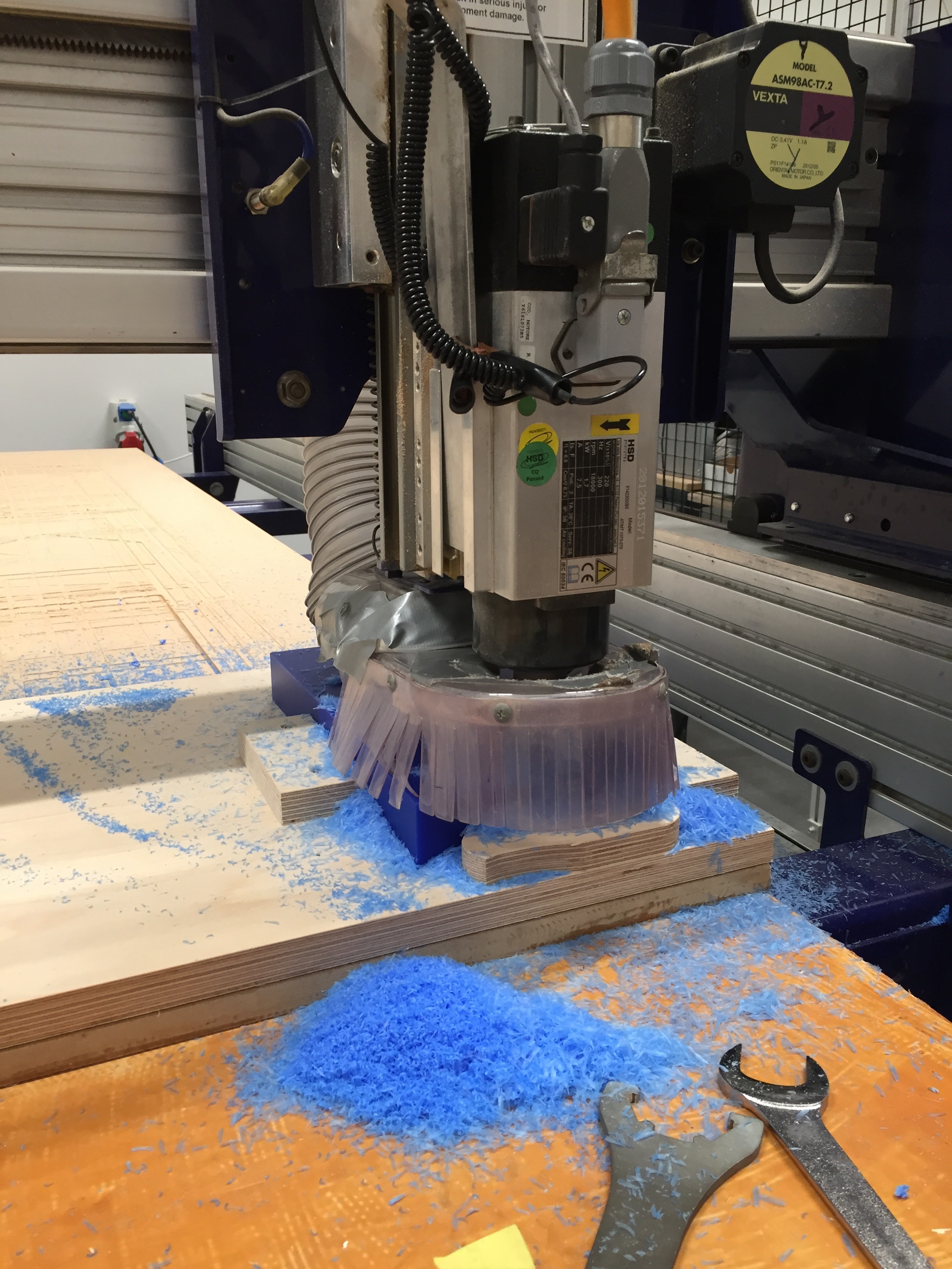
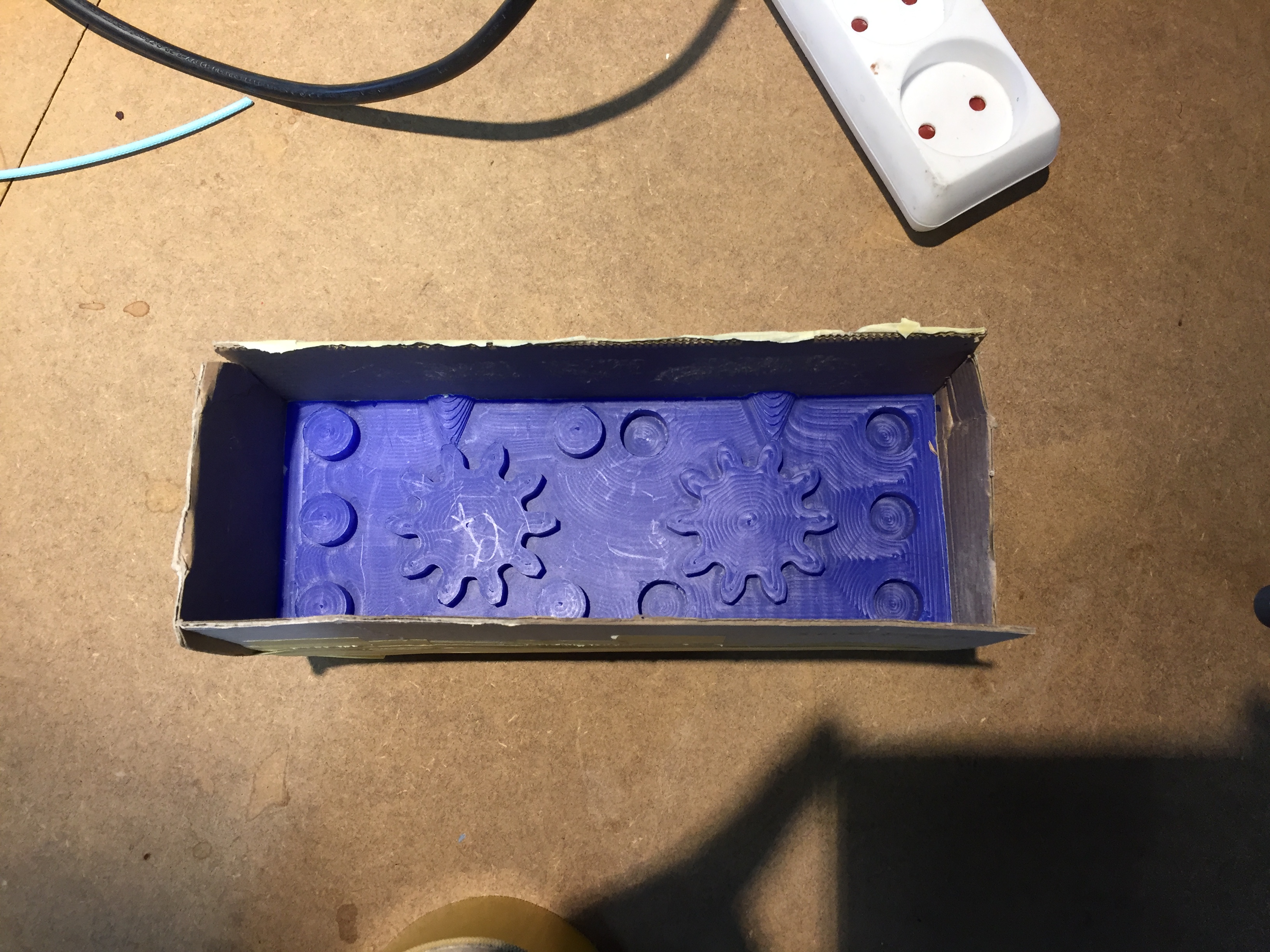
When the job was done I saw that the air vents had not been made simply because the bit was too big for such small things. To make air vents I instead printed some small rods that would make up for the missing air vents.
Casting
After I had machined the 3D design it was time to make a silicone form. I made some edges to the design I had with cardboard in order to hold the silicone in place. The silicone I used was this one.
Next I would mix the silicone mix and pour it over the shape.
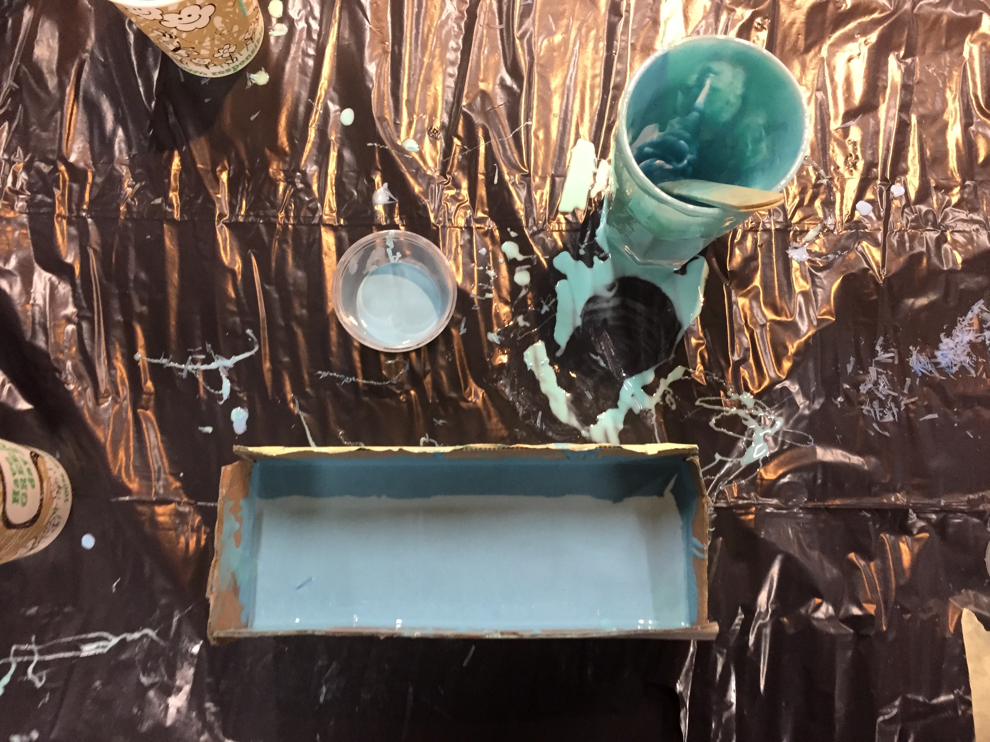
When the silicone had time to settle after 75 minutes as described in user manual for the product I removed the form.
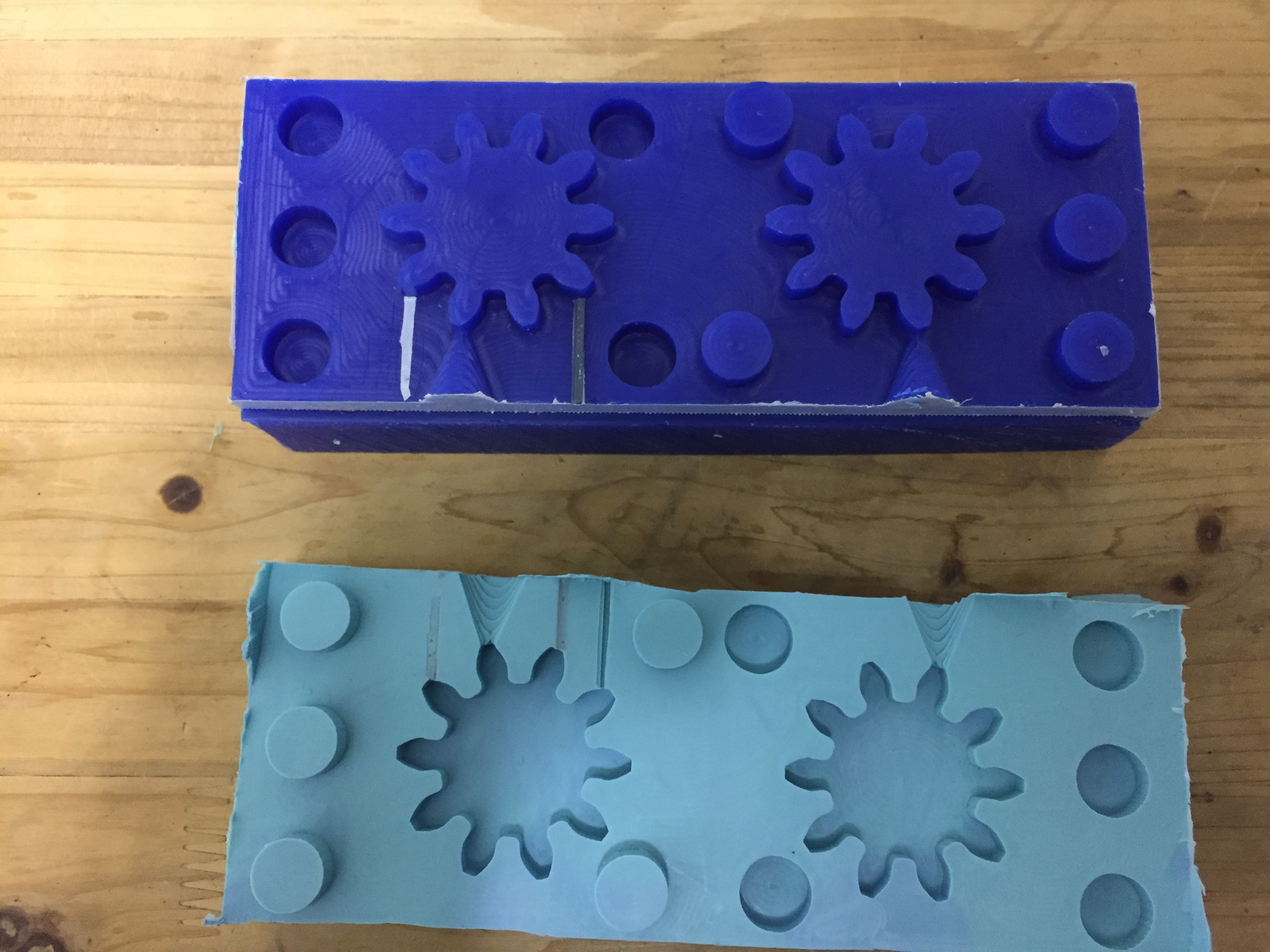
Next I followed a similar routine when pouring plastic liquid into my form. I used a plastic form the same brand as the silicone, this one. The challenge was that it was hard to press the two sides of the form together so that no liquid would run out. I used tape to hold them together but I think I should try another method next time I'm casting, since the gear was not completely perfect. I think my air holes worked but the two sides of the model was not compressed properly together in order to have a even distribution of material.
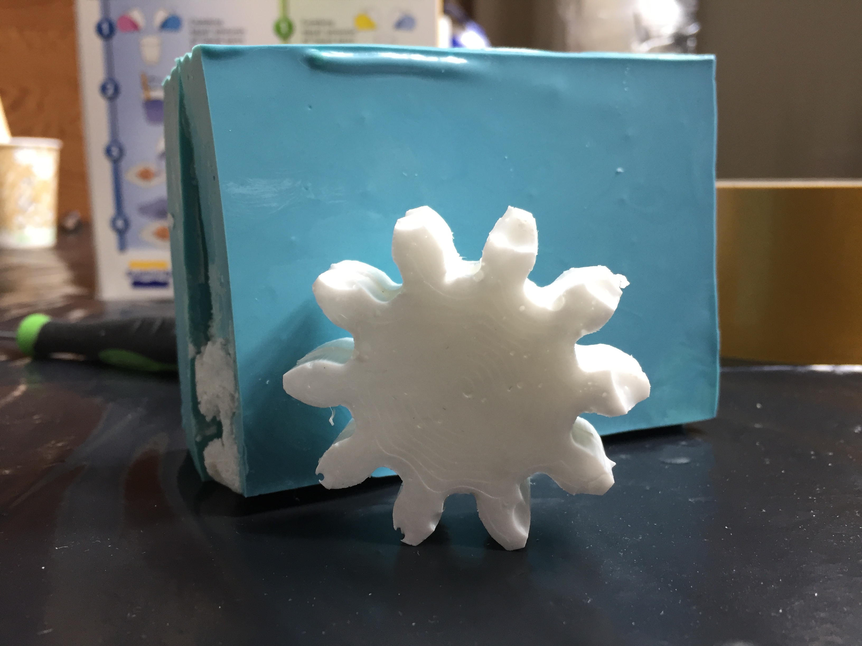
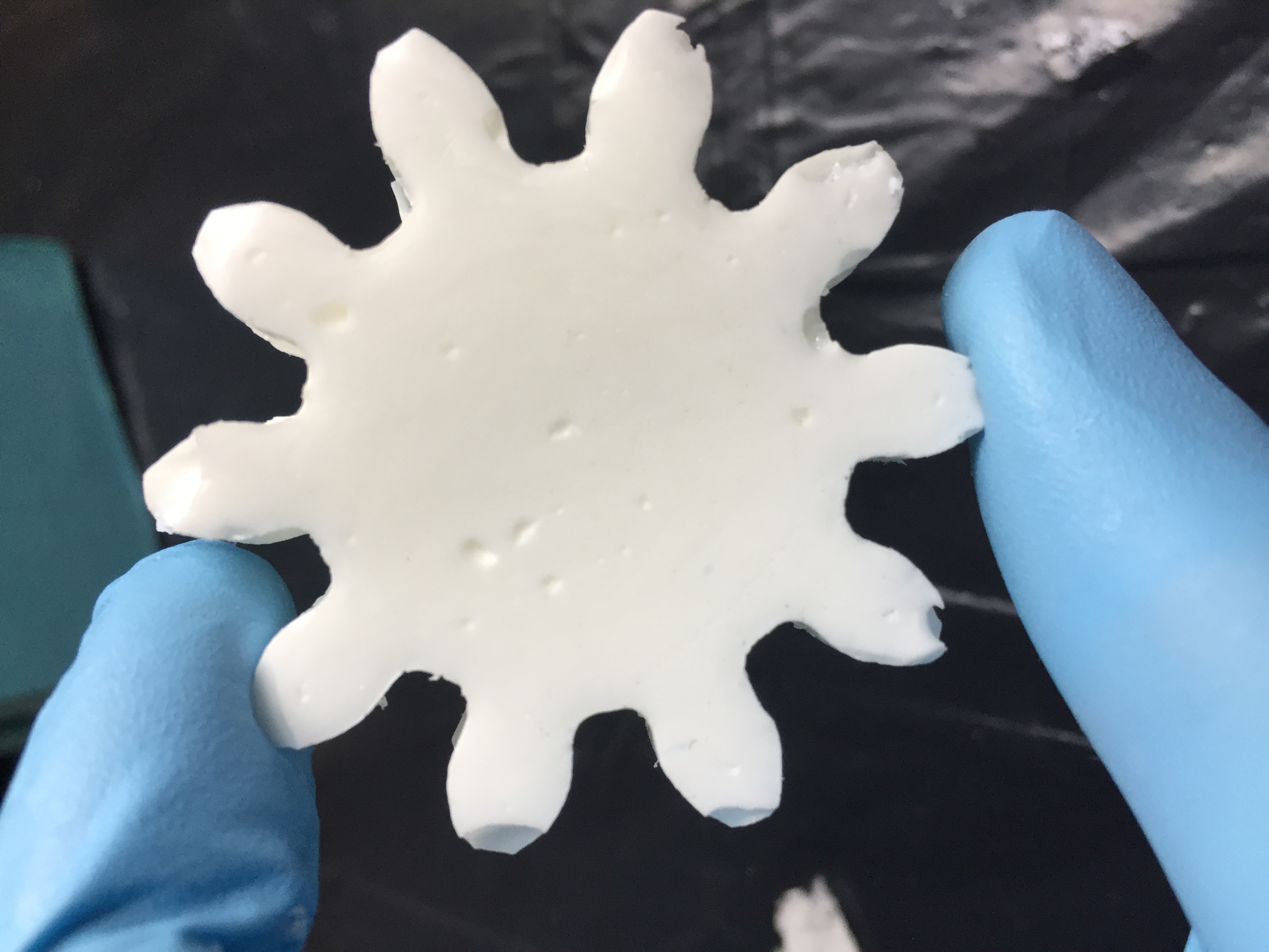
Improvements
As this was my first time casting and molding there are a few obvious mistakes to take from it as improvements for next time. For making the silicone mold I should insure to have a big enough cup to mix the silicone in, which will make it easier to thoroughly blend it and therefore the resolution will be better. As seen in the picture of my gear the resolution of the cast is not that great after all. The reason for this is that the silicone form was being held together by tape when the casting was being done. This caused the connection between the two sides of silicone to not be tight enough to cast quality parts in it. To account for this a solution could be to make another assemble mechanism or only have one side of silicone to cast in so nothing will have to be assembled, but this will complicate the escape of air since air holes can't be added with a solution like that.