Characterising the Roland SRM-20 :: Electronics Production
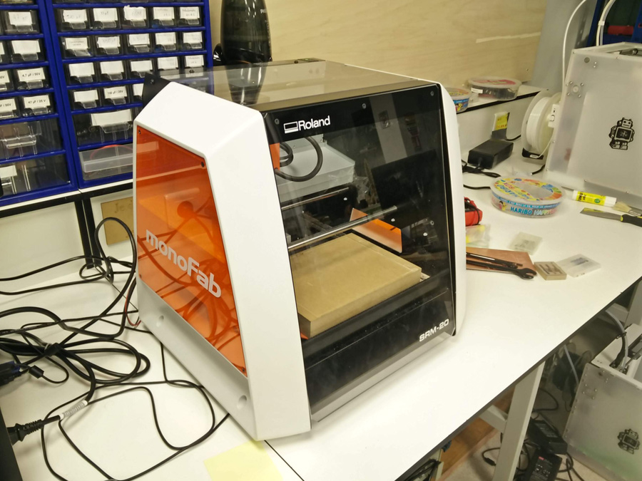
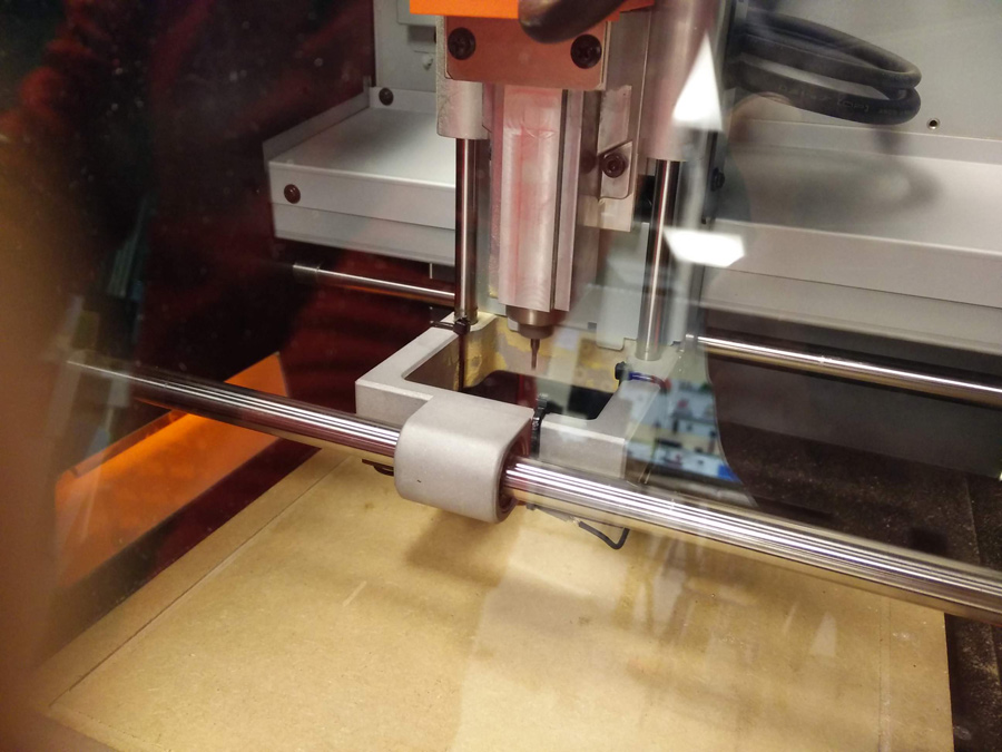
We started our learning of the SRM-20 by turning on the machine leaving the spindle run for ten minutes, a good habit for effective cutting after a break in usage.
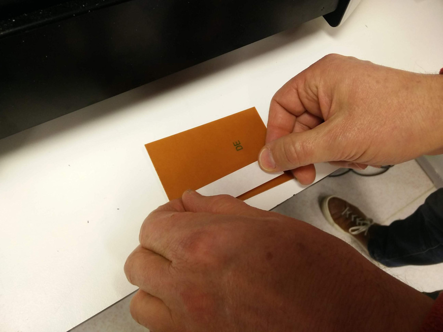
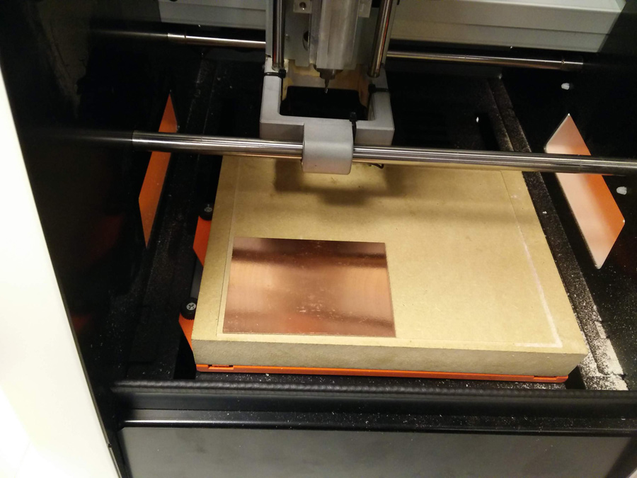
Double sided tape was applied to the back of a new copper plate. This plate was then set on the sacrificial board for cutting.
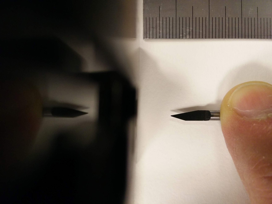
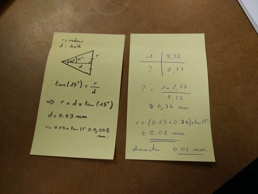
We selected the appropriate blade for cutting the pcb. From a close photograph, and comparing the copper and blade dimensions, we calculated the potential cut depth.
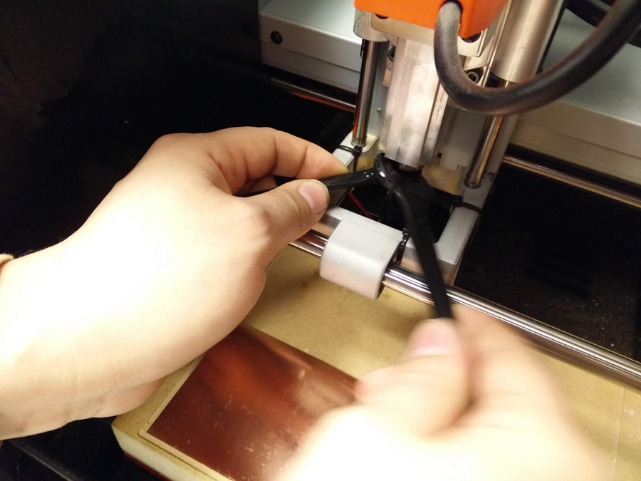
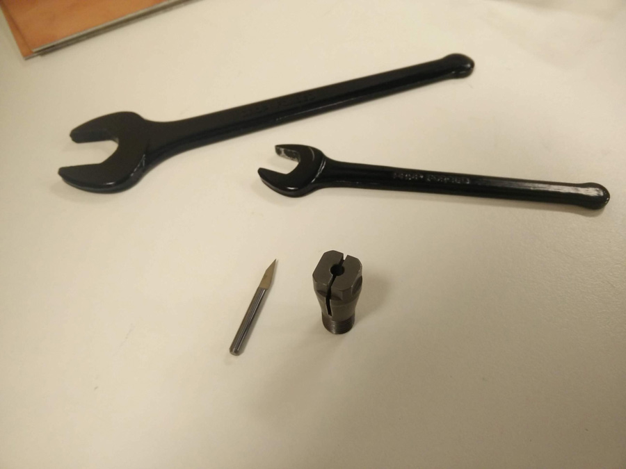
We removed the existing blade and collet from the machine using two small spanners.
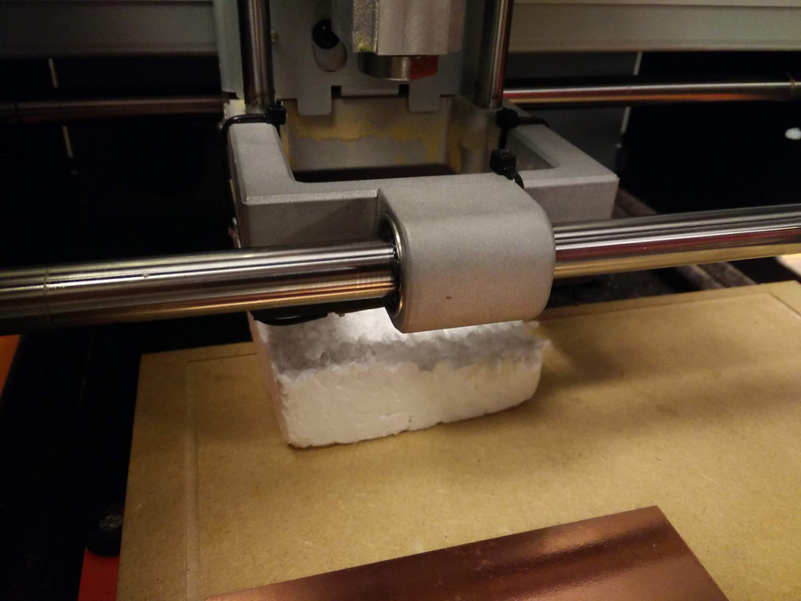
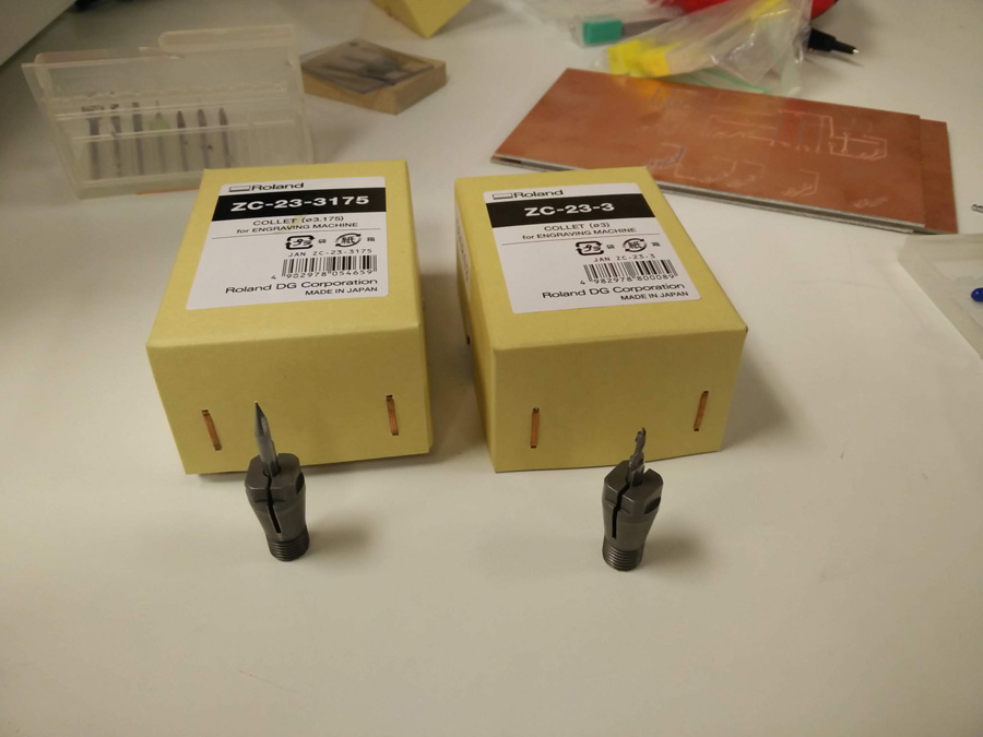
A chunk of polysterene was placed below the blade in case it would fall and be damaged. Different collets are for different blades – To know which is the best fit, consider a 'snug' fit when applying.
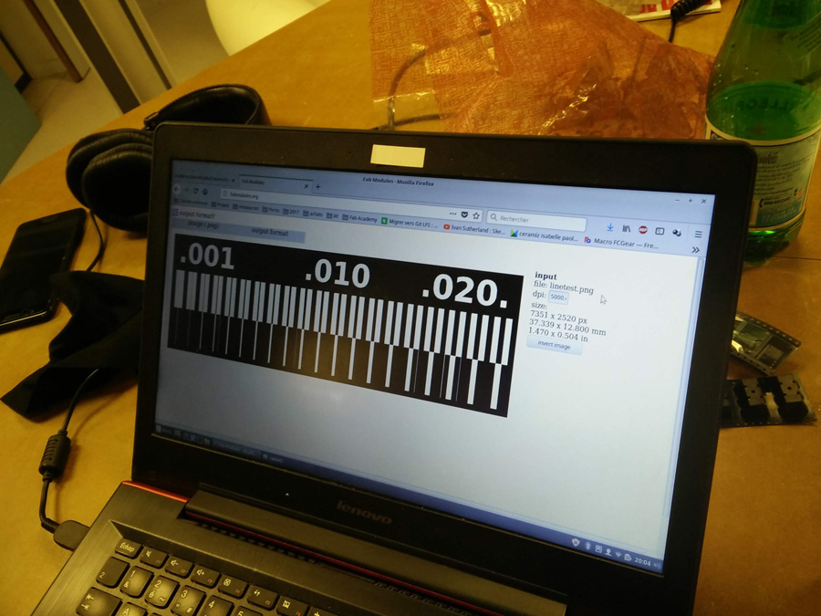
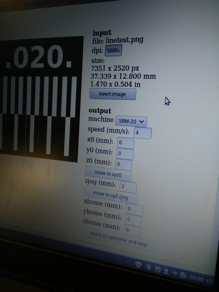
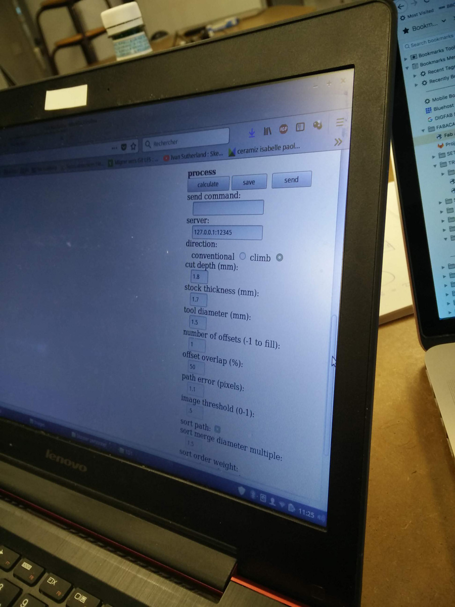
Back on the computer, we loaded the test files into fabmodules.org. The settings for output were png, srm-20 and pcb trace. The file was sent directly to usb using a linux computer.
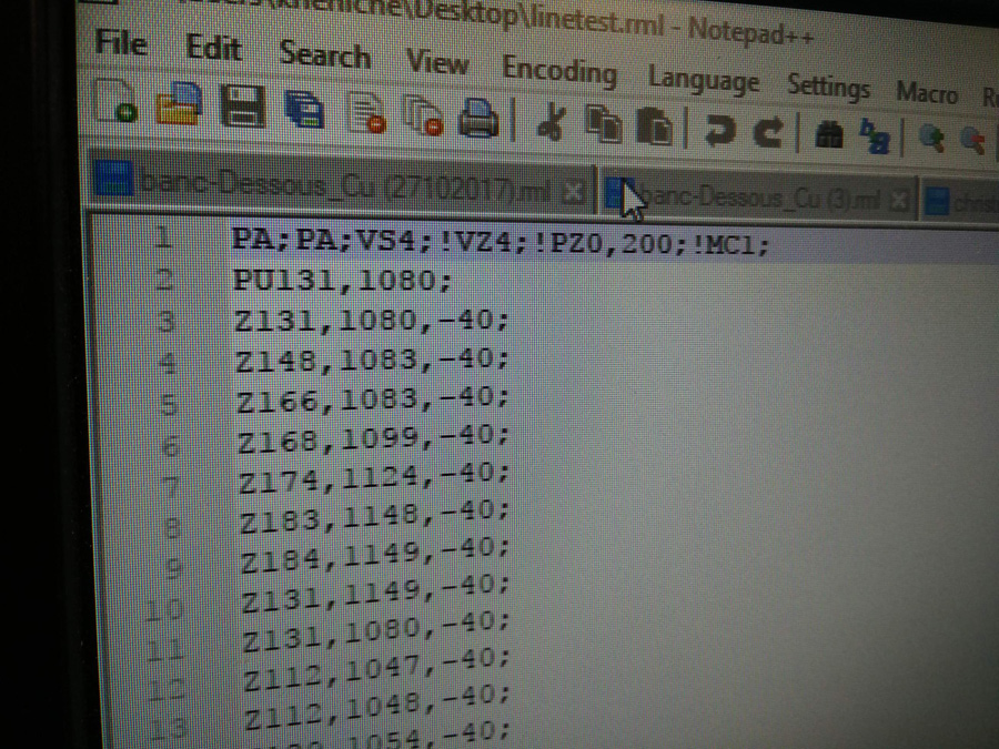
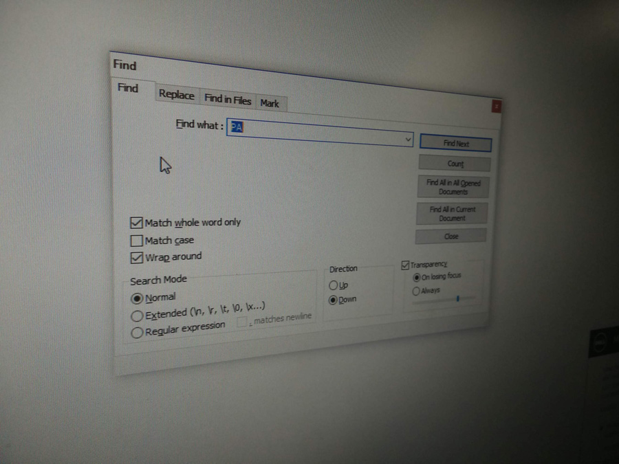
It was recommended to open the file with Notepad++ to check that the coordingates chosen using the wyswig on fabmodules matched the end file. Any last minute adjustments could be carried out with a simple find and replace.
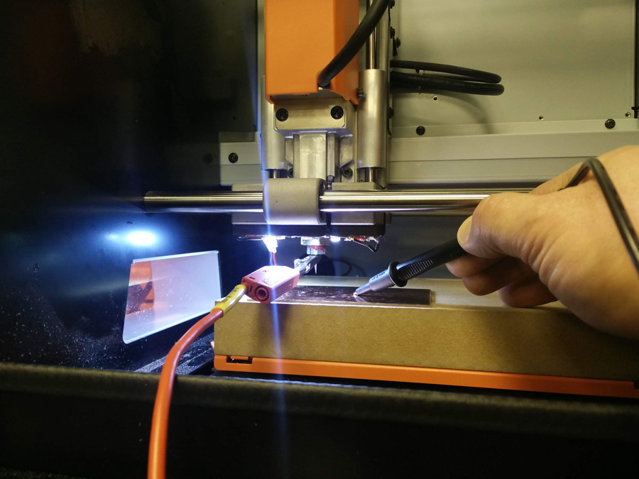
The multimeter was used to set the z axis. The spindle was brought down slowly to touch the plate – First x1, then x10, then x100 to move the spindle a fraction closer each time. The multimeter's aligator clip was attached to the spindle and the other outlet was held against the copper plate. When the blade touched the plate, the multimeter sounded out, and we had our z-coordinate.
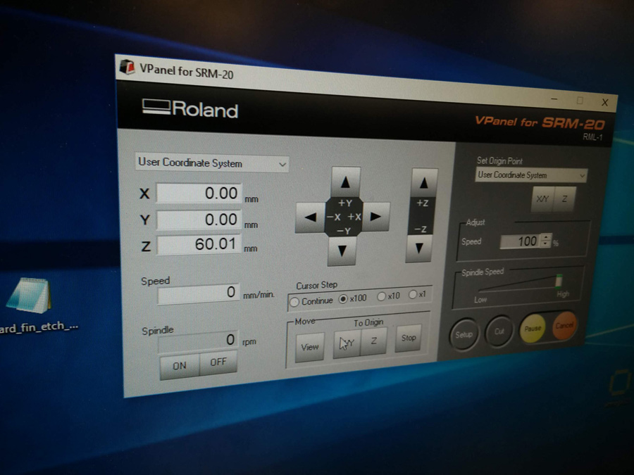
As this was a new board the x and y coordinates were set by eye and manually moving the spindle over the board. When we were happy that enough of a margin existed, we set the file by pressing the xy button in the set coordinates section of the interface.
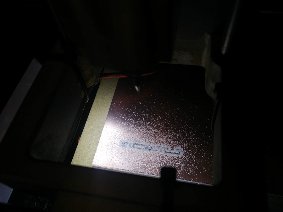
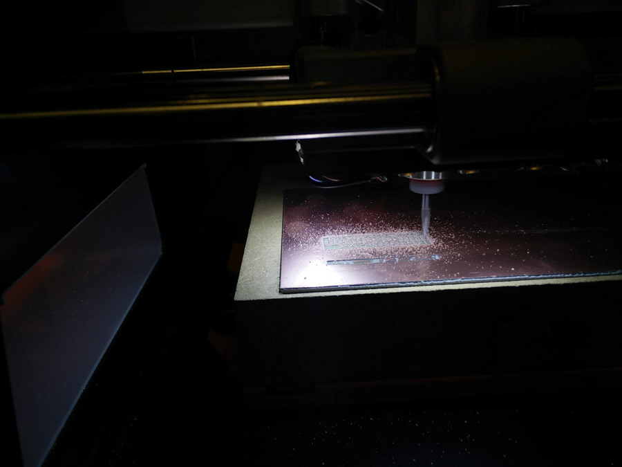
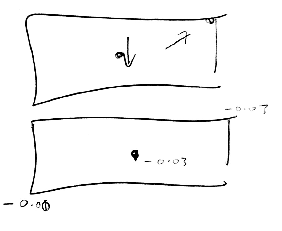
We realised early into our first cut that the z-axis was off and had to be adjusted. A big issue going forward was slight bumps on the surface of the copper plate and this meant there were variations in cut depth. It was recommended by Vincent to find the z-axis in a diagonal line across the board, as outlined in the sketch above. We therefore took the most common amount or an average of the three points.
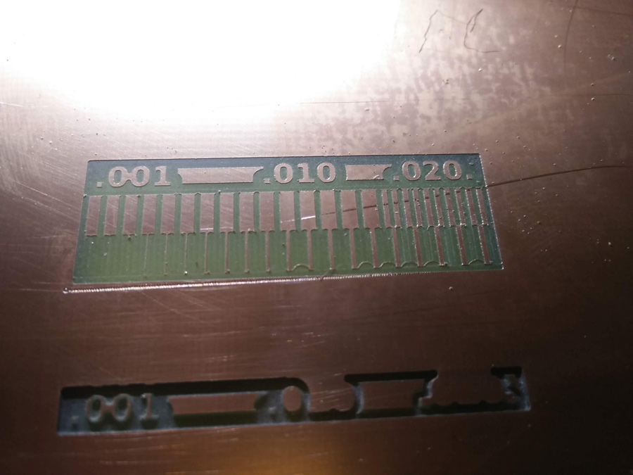
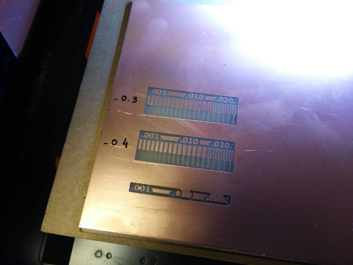
A successful test cut at -0.4mm was achieved. We followed up with a cut of -0.3mm.
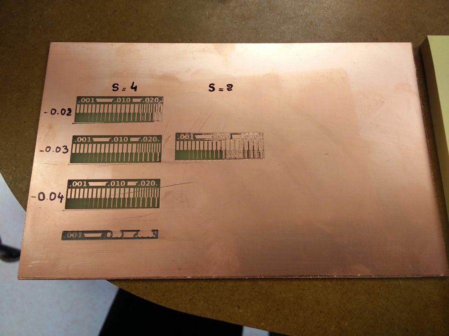
In our third test, the -0.2mm cut was starting to fail.
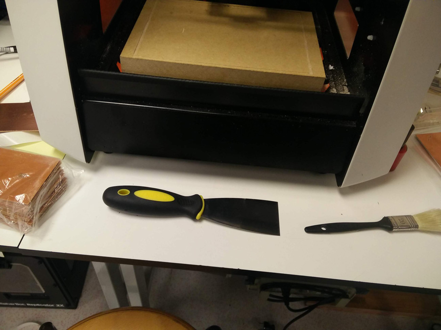
Up til now all test were conducted at a speed of 4. We did a final test with a speed of 2, which failed also. We removed the plate from the sacrificial material using a paint scraper. A paintbrush was often used to clean out debris./