Brainstorming
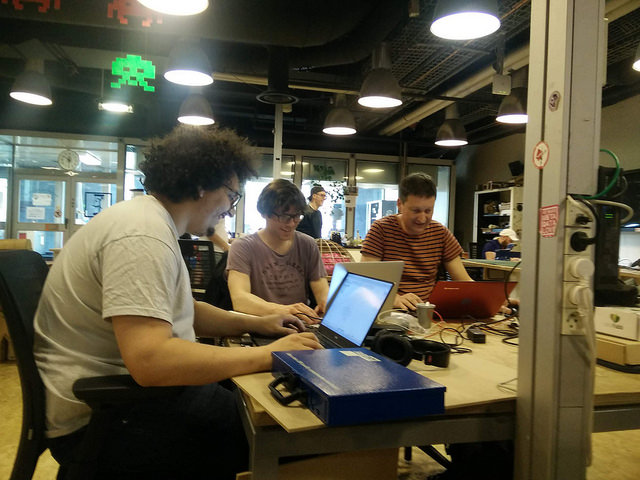
The first task brainstorming ideas. Amongst other things we looked at the work of past students such as Tommaso Spagnoli.
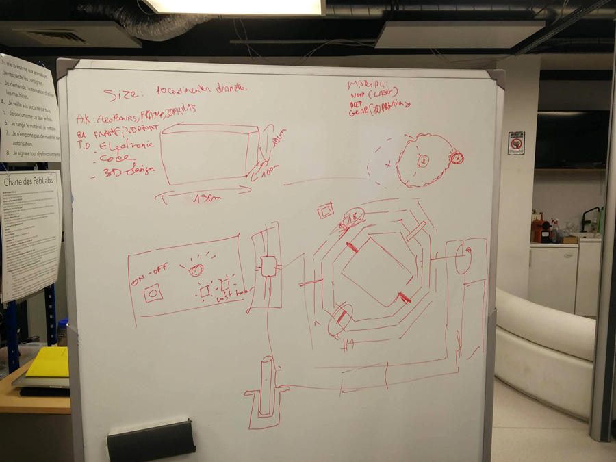
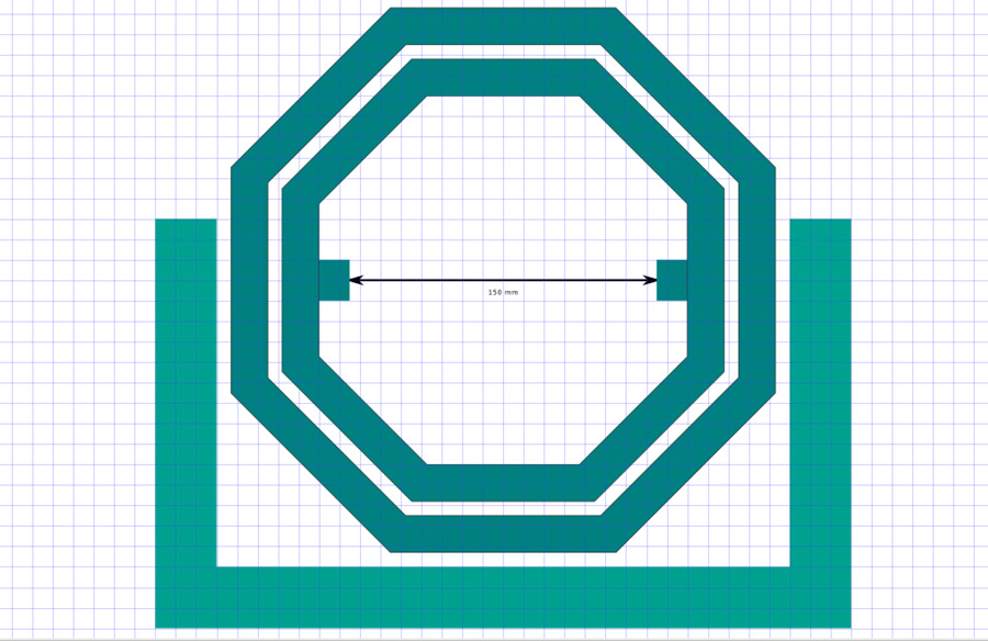
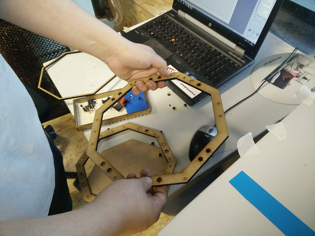
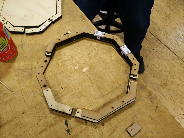
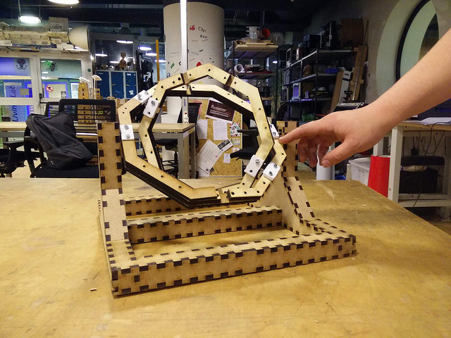
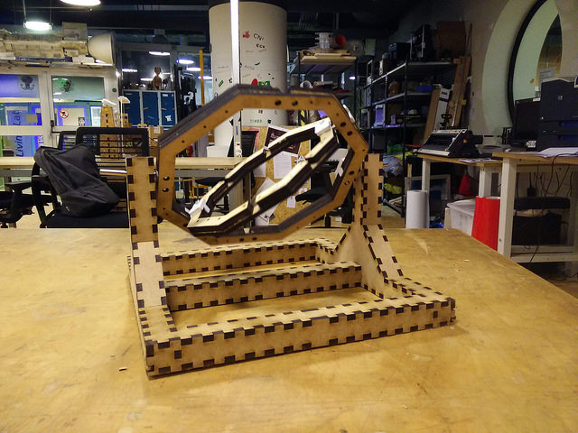
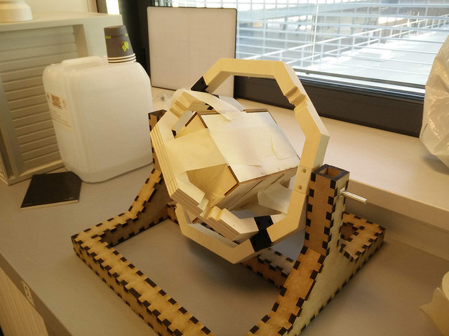
On reflection, we felt that an octagonal shape would give the strength to the axis: An external axis to rotate the mold vertically and an internal axis, picking up on inertia and rotating the mold diagonally. The rotation would happen around 4 lengths of metal piping (6mm thick) – two longer lengths would support the rotation vertically, to be machine driven. The two smaller lengths were for the inertia-driven rotation.
We also considered creating a strong base and supports for the axis, using press-fit construction at a suitable height. There needed to be enough room for the full frame to rotate.
We defined the dimensions of the mold chamber as 150x100x100, allowing for a wide mold or possibly, three smaller molds within the space. It is important that the chamber is liquid-tight to avoid any spillage. We discussed the use of glue and straps along with press fit construction.
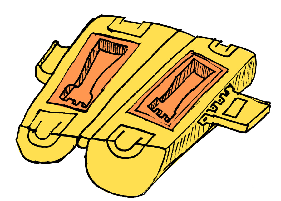
The first attempt at visualising the chamber was to make a cylindrical shape with a replaceable tray (seen here in yellow and orange). It would have to be 3d printed which have lengthly 3d printing time.
Instead of using the bars to hold the chamber, the suggestion was to use bolt it with a hinge to the octagon.
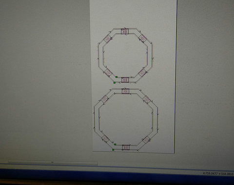
Separately we designed the axis, base and chamber files for lasercutting. We then gathered 6mm, 10mm and 3mm MDF for each. The files were cut from Inkscape to the Trotec accordinly.
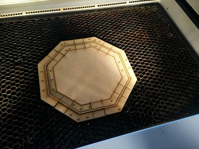
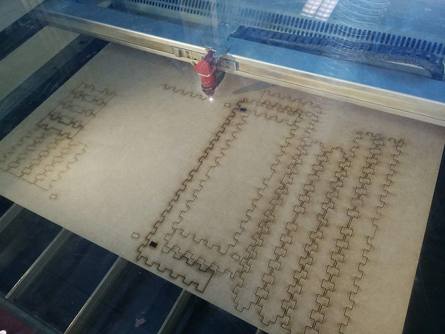
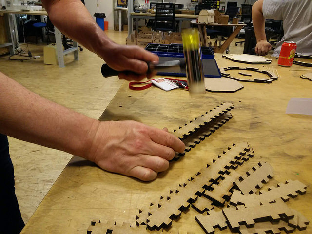
Some of the smaller elements proved challenging to remove from the material.
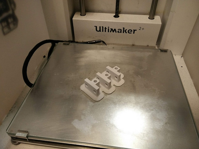
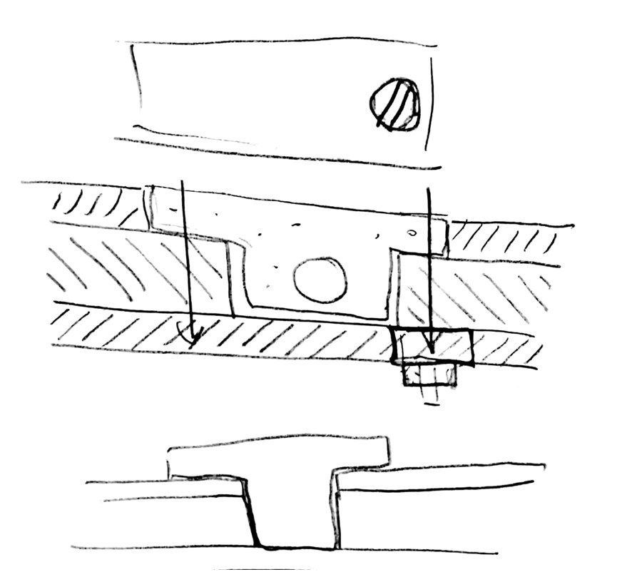
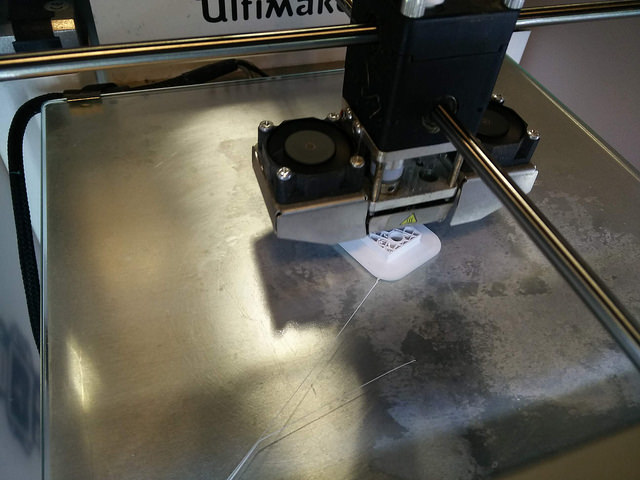
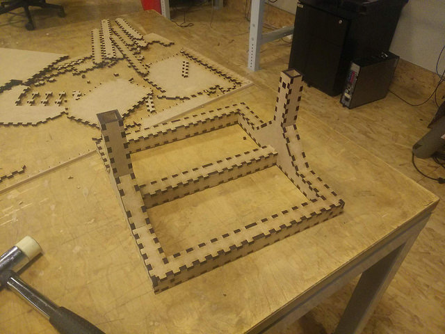
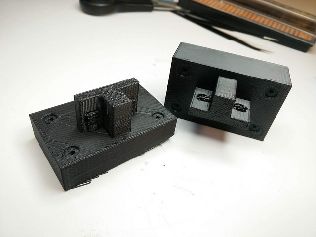
Joints to assemble the octagon firmly were drawn up. These would position the screws at an angle way from the moving elements. The joints were built in 3D modelling software and printed with the Ultimaker 2+.
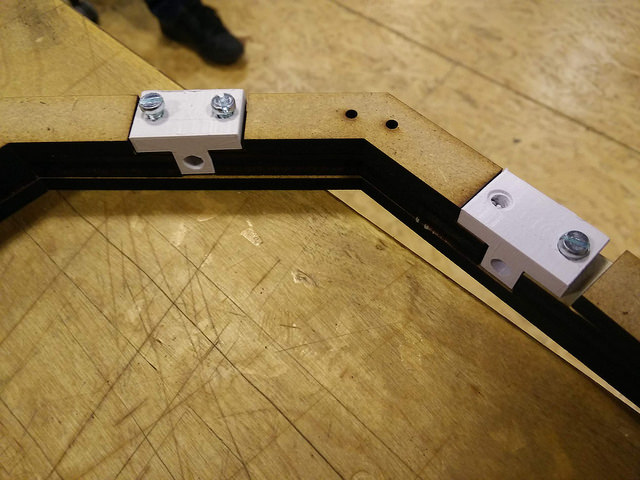
This early prototype screwed together in a looser manner than we expected.
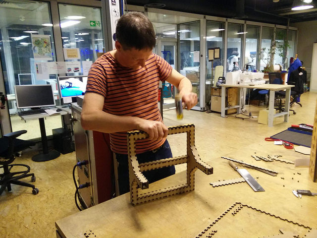
A mallet with soft edge was used to apply a certain amount of force to the proceedings!
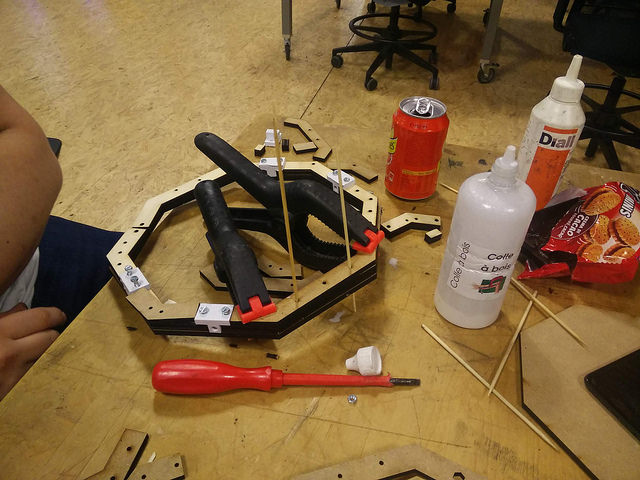
Glue and grips were used to stick three 6mm pieces together to form an 18mm thick octagon. Sandwich picks were used to keep holes free of excess glue.
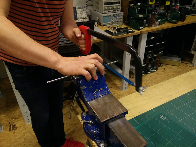
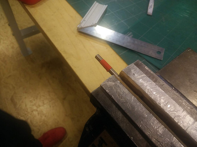
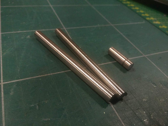
We cut our metal piping to size from a larger piece. The metal saw generates a lot of heat so care we taken. A pencil and later electrical tape was use to guide the exact cut position.
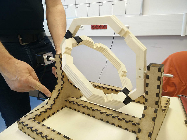
In a test at the end of the first day, we were able to support and rotate the axis on the base. Good result after a hard day's night!
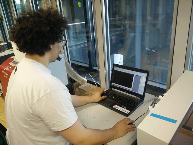
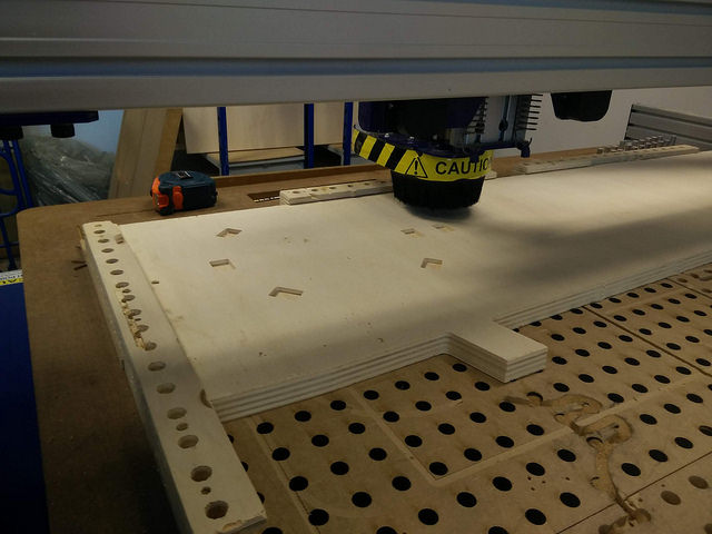
Adel worked to create an improved stronger axis on the CNC.
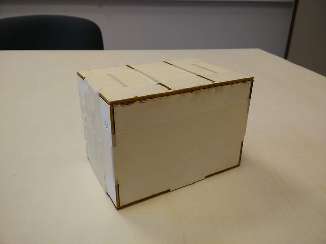
Ben developed the inner chamber as a press-fit box.
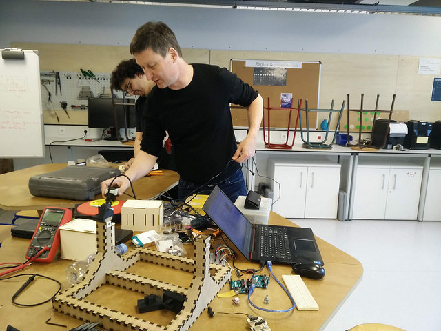
Thierry and Adel developed the code to get the motor running. They positioned it on the base.
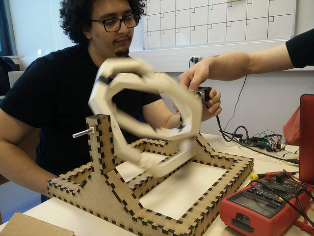
A quick test with the chamber in position.
Revised Physical Parts
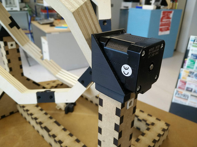
We worked on several new parts: A piece was created on one side to hold the stepper motor in position. It was essential to fit the dimensions of the frame and axis. Parts were designed in Fusion 360 and printed using a UP3D Tiertime 3D printer. We considered at this point how the main and encoder pcb boards would sit on the base.
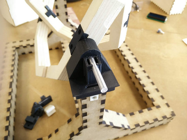
Key to the machine was support the axis with a metal bar on the opposite side to the motor. This piece needed to hold position, while at the same time, allow freedom of movement. Alternative shapes, and springs were considered before design and print.
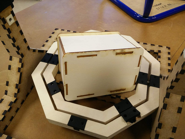
The mold chamber was improved to be better press-fit without glue. The pieces were designed in Fusion 360 and exported as flat sketches (.dxf) to Inkscape. From here, they were prepared as an SVG and cut with the Trotec lasercutter.
Two connector parts were also 3D printed to close the distance between the chamber and axis. They were prepared with a right angle to fit the pockets of the axis.
Electronics: Wiring/Breadboards/Components
We considered the interface would allow users to operate the rotational molder. We chose to use a small Uctronics LED which could provide various menus to adjust settings.
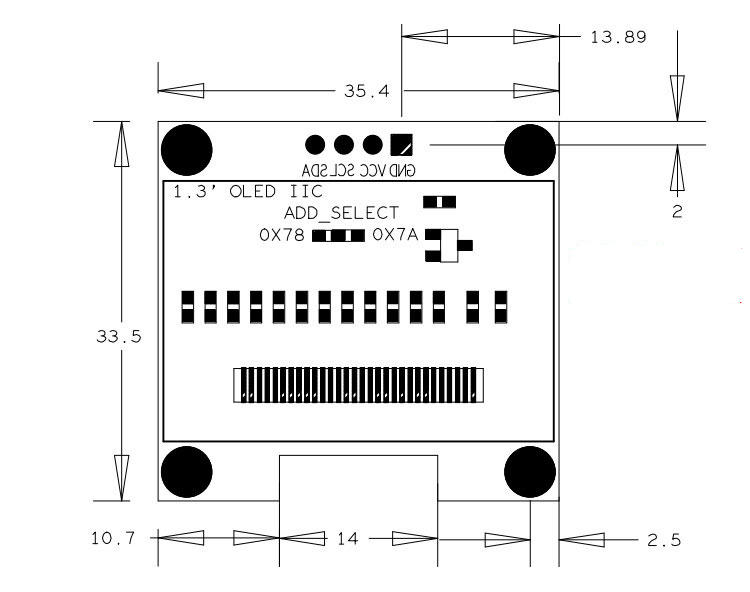
We reviewed the datasheet and considered the number of pins, including those required for the motor. Early on, it seemed clear we would work with a ATMega as the number of pins was high.
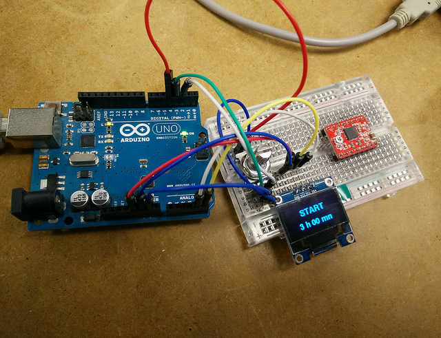
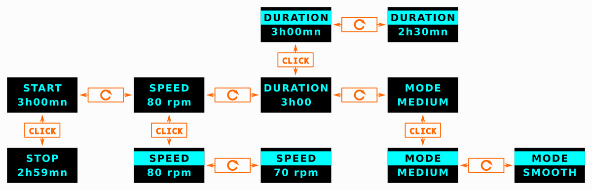
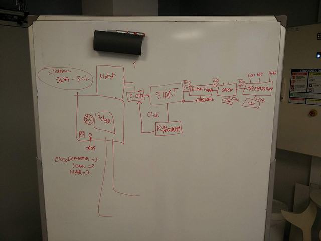
The encoder has a dial and button and we worked out the menu on a breadboard. The following photos indicate the steps of the menu as you rotate the dial. First is the 'Start' with a default three hour duration. Click once to start the machine.
Boards: Eagle/FabModules/SRM-20/Soldering
We worked to complete the machine and documentation for Wednesdays deadline. Parts were drilled and press fit as required. Then came the time for planning and designing a board for the microcontroller.
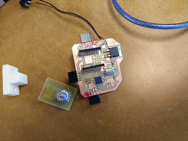
We built pcb boards with using Eagle, Fab Modules and the SRM-20. A lot of trial and error was involved to cut such small routing for the ATMega and other components.
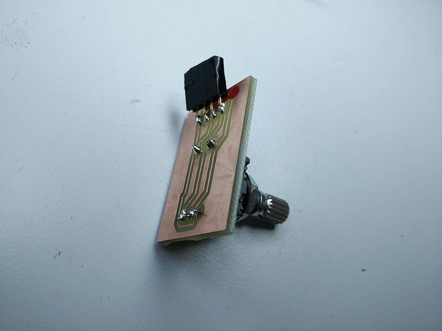
A separate board without VCC was designed for the encoder.