Electronic production.
this week assignements are:
- Characterize the specifications of your PCB production process (group project)
- Make an in-circuit programmer by milling the PCB (program it, so that you can use it to program your board in Electronics Design week, and in other weeks
- Optionally, trying other processes.
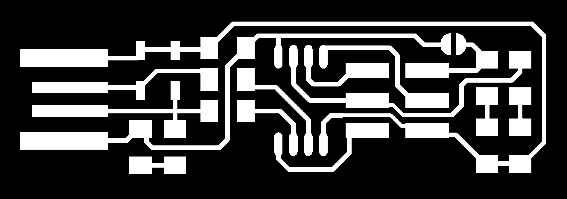
Download the PNG file
The first step is to read the documentation made by brian where you'll find everything you need to know
for making you first board.for making your board, you start by dowloading the PNG file of the traces & the Outline.

Using Fabmodules
When you download the png file , is time to transform this image into some cutting path for the SRM20.
for that we are using The fabmodules,Fab Modules allow to produce files for different processes using machines typically found in Fab Labs. we can use int for almost any tool you can find in a fablabs, the one we will work with today is the ROLAND SRM20
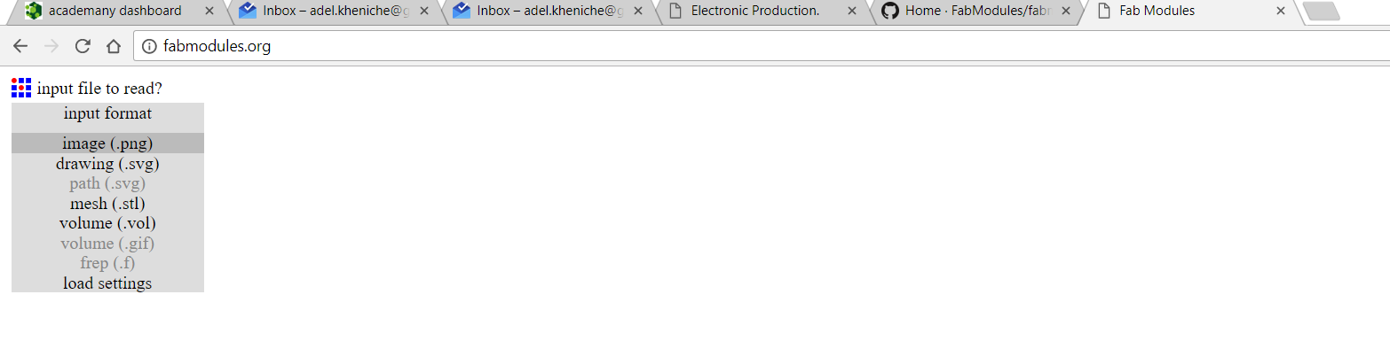
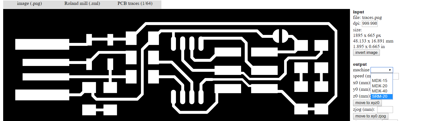
first step is to go to fabmodules.com there you click on import. and you can see all the type of file you can import. we need to import some PNG.
 then you have to choose your output format. each machines have their own language. here we need to use Roland mill for the SRM20
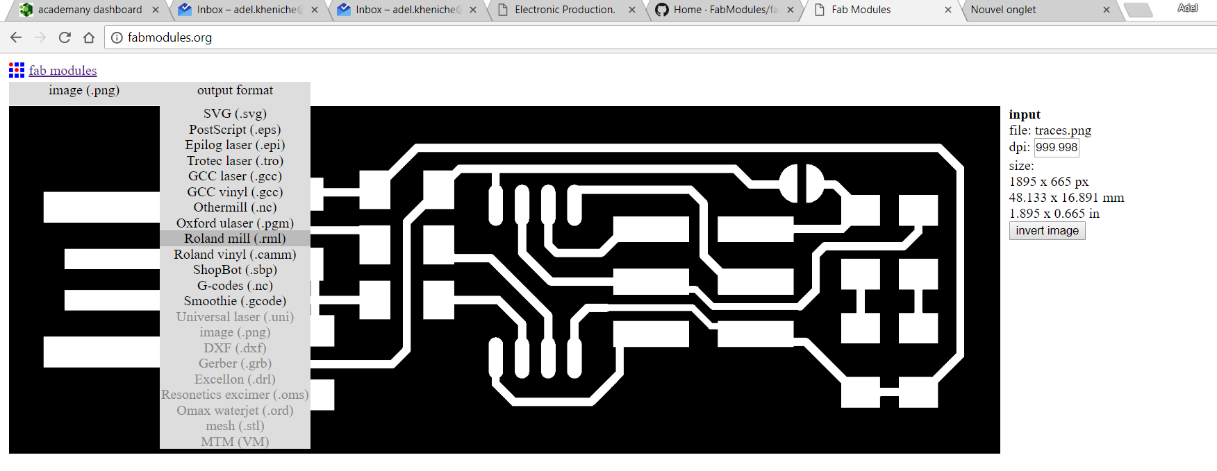 the pcb is made from two file, the outline and the traces. the traces will create the path and the connection between the component.the outline will cut the board.
 your not using the same bits for the outline or the traces. and we always start from the traces.
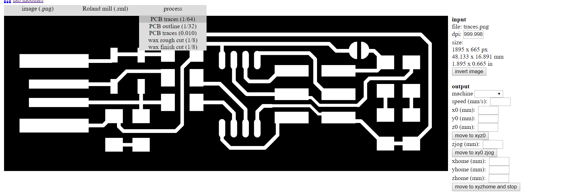 after choosing the Traces 1/64 we have to choose wich Rolland we are using. in our case. the SRM20.
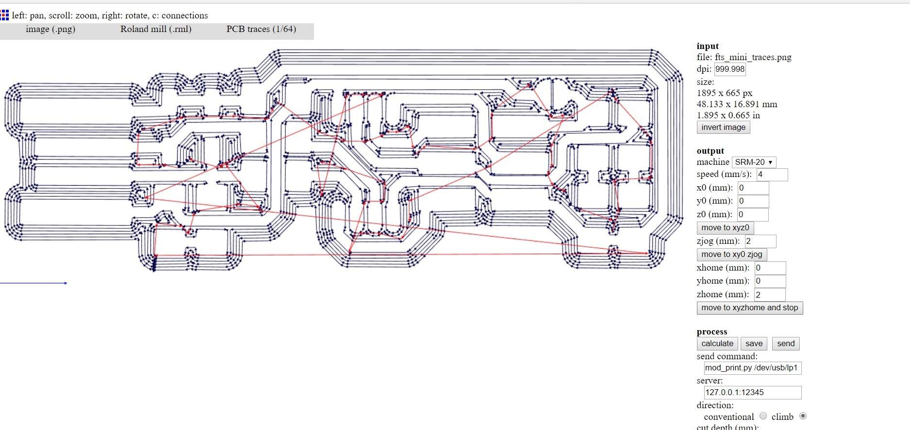
 when you did all this stuff is time to make the RML file.
Make a RML file
The first step to make our own AVR Programmer, is to Take the PNG file and transform it on RML file type.
For that we are using fabmodules.org Make the engraving file
After our group test for characterization the SRM20 i found that the best result was on
- 0.03mm depth cut
- 4mm speed
- 8500 RPM so i used this parameter and made my own rml file with the FabModules
- start the SRM20
- how to using double side tape. on PCB.
- how to choose a bit.
- how to install it.
- how to make the Z zero with a multimeter
- Outline file(RML file)
- Traces file (RML file)
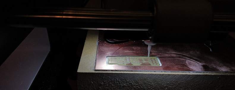
How to use the SRM20
For using the SRM20, i made a video explaining every details.You'll find in it:

Make the cuting file
For making the cutting file, its pretty the same process but we choose Outline on the process, the value we need to modify is the cut depth and the diameter tools.
so we are using 1.50 end mill diameter for cuting out our board, for the cuting i have always this rule that work perfectly with the Shopbot tools not cutting more than an half of diameter per path

Soldering
after i finished to mill this pcb, i started to try to solder some cms 1206 (0.12X0.06inch) package on test board, for learning how to solder, really good exercise and make you gain some time on your project
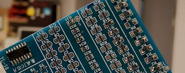
 After making some good solder on it soldered my own pcb.
i made a piece of paper and exposed every component on it for knowing witch component goes where.
After making some good solder on it soldered my own pcb.
i made a piece of paper and exposed every component on it for knowing witch component goes where.


i started by soledering the Attiny45 on the board like said on the documentation of Brian after the ATtiny i soldered every other component
For the led i wasn't sure of the way of soldering them, i discover that every manufacturer had is own way to let you know the Cathode/Anode so after looking on the datasheet i discover how to solder mine.
MY pcb was Finally OVER !
Programming a FabIsp with a FabISP
Programming the Fabisp we need to use the FabISP so Vincent Dupuis give us his fabisp and we used it to programm our own.
For doing that i used an Ubuntu software.
s
i opened the terminal and install avrdude for that i used the following command:
sudo apt install avrdude gcc-avr avr-libc makeafter that we need to unziped the file we download :
unzip fts_firmware_bdm_v1.zipthe next step was to plug the old Fabisp on the new FabISP for that we checked the way that the pined on the old was connected, and we connect every Miso on Miso, MOSI/MOSI etc.
 when everything was good we started the last line of code :
run Makeand voilaa! it's up and running!
Troubleshooting
When i milled my PCB i discover to not push to much the mill into the collar, i lost 2 hours looking for a weird error. when the cut was on it's last pass he was always going up and making it outside the cut (like in this video) i discoverd that the Z was as is maximum, and asking it to go more down wasn't possible so for security the mill is going UP and making a cut out. so now Ater i installed the mill on the collar, i always go on the sacrificial material, push down the Z to maximum, go up 1mm, and push out till it touch the sacrificial material. this way i'm sure that i have enough mill to go trough anything i'm cutting, without damaging to much the sacrificial material.
What i've learned
Milling a cms Board was a first, i learned to solder CMS component! --
file of the week.
here you'll find the file of the week
For downloading
right click and save as