
Output Devices
Assignment
Add an output device to a microcontroller board you've designed, and program it to do something.Active Buzzer
A magnetic field detector can not be silent! so… I had the idea to add an active buzzer to my electronic board.
White and Blue Led: another Output Devices
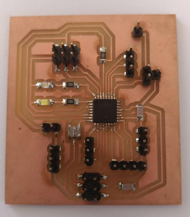
Integrated on the board I have prepared two LEDs, a white one that indicates the power-on status, a blue that signals the detection of a magnetic field by flashing in synchronized way with the buzzer and also signaling the transmission on the serial port. This is the part of my code about communication blue led: Arduino Wiring Code: //blue led blinking synchronized to sensor_value {digitalWrite(comled,HIGH);delay(map((sensor_value),20,1023,1,10));// comled power on digitalWrite(comled,LOW);delay(map((sensor_value),20,1023,1,10));// comled power off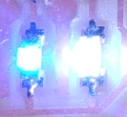

Synchronized with the sensor value
In the code I predicted that the duration of the sound is synchronized with the value of the sensor, this uniforms the different sound and visual outputs. Arduino Wiring Code: //sound zone //start beep digitalWrite(pinsound,HIGH);delay(map((sensor_value),20,1023,1,10)); //end beep digitalWrite(pinsound,LOW); // the sound are synchronized to sensor_value than blue ledAll Output components
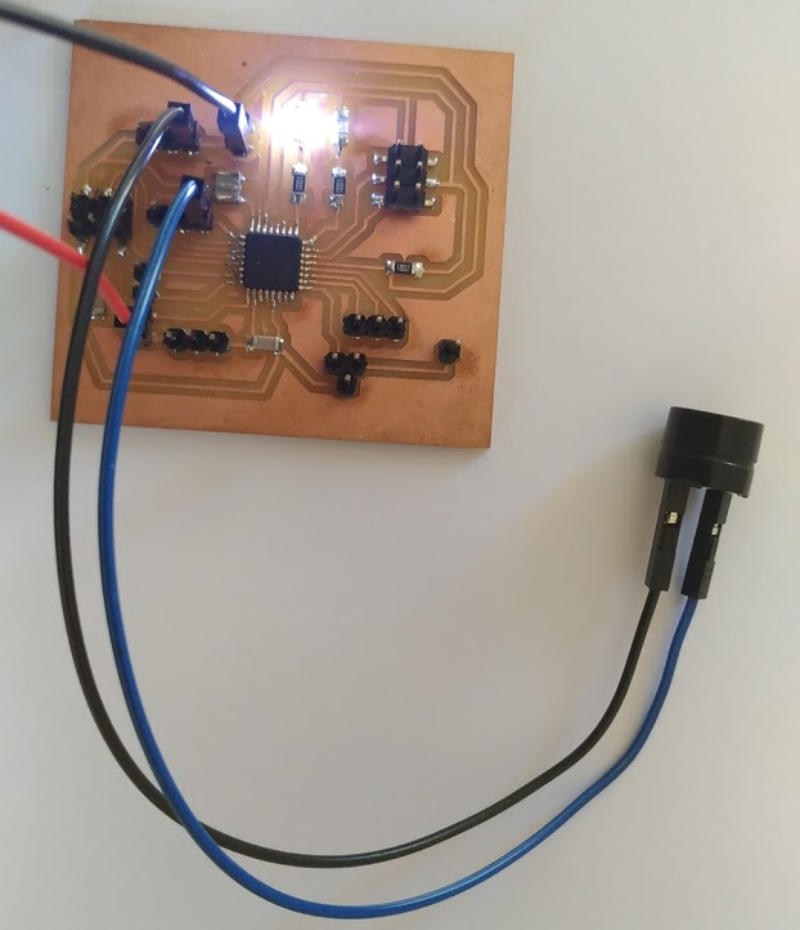
In the video we can see all the output components of the hall sensor board working in perfect sync. The idea was to use the sensor value to time the light and the sound. I am very satisfied with the result. A further consideration is that the card has other pins available and has connectors for vcc and extra gnd ... so in the future I can expand the potential.
Original Files and Useful Links

where can I connect it?
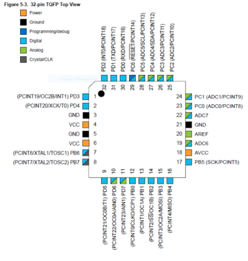
I have a digital output on pin 9 of the ATMega328p and I can use it to connect the buzzer.
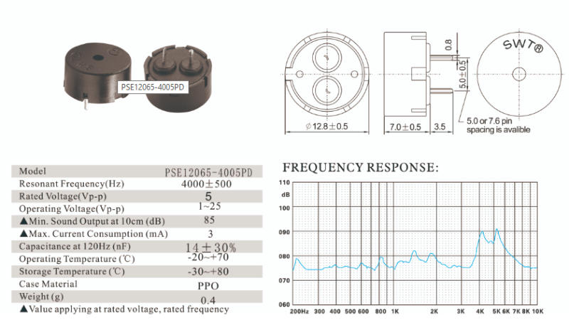
this is the buzzer data sheet

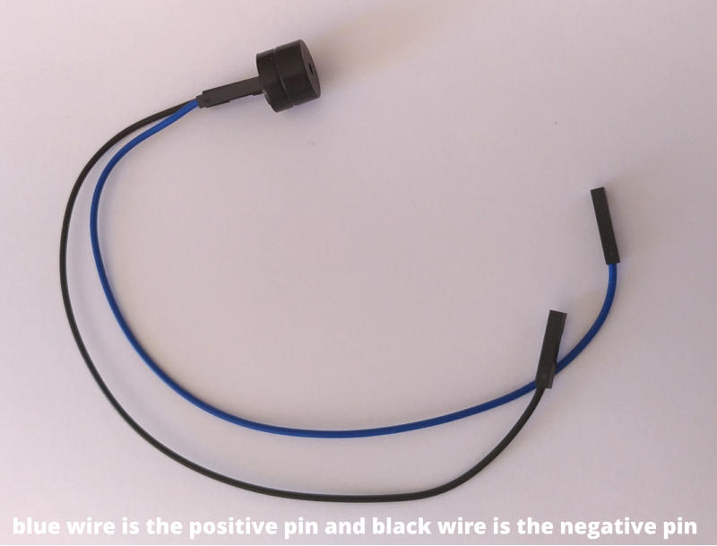

The number 9 pin on my hall sensor card, here the blue wire will be connected.
The black wire is connected to one of the GND pinheader pins
- GND

Pin-out of
ATMega328p TQFP
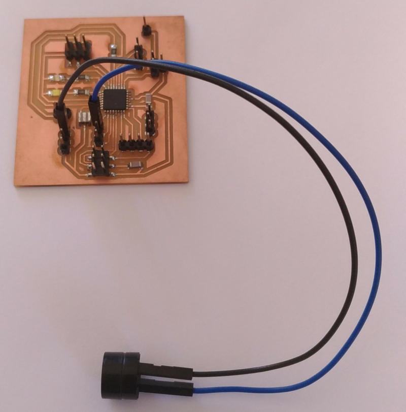
The buzzer connected to my board
I added the VCC and GND pins from my programmer

the buzzer connectors

Develop the code to create a sound!


: Upload the code to AVR
First
of
all
I
need
to
connect
my
mini-USB
programmer
to
my
card
and
transfer
my
code
to
the
AVR
microcontroller.
I
will
use
the
Arduino
software
configured
to
work
with
my
external "USBtinyISP" programmer.
after
the
splash
screen,
the
arduino
editor
is
ready
to
work.
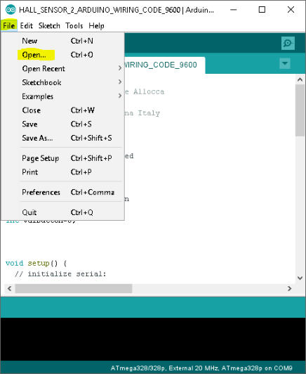
Now
I
can
load
my
program
via
the
"file"
menu
by
selecting
"open".
At
this
point
I
can
select
my
programmer,
choosing
the
appropriate
model
from
the
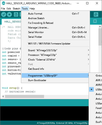
"tools"
menu.
To
send
my
program
to
the
Electronic
Board,
I
use
the
tool
in
the
Sketch
menu
"upload
using
programmer"
.
When
the
transfer
is
complete
and
the
card
is
reset,
the
program
starts
and
I
can
check
it
to
see
if
it
works
properly.

Power on
white led
Com on
Blue led
No sound ...my little problem this week.
After connecting my card to the magnetic sensor and the buzzer, I did not hear any sound when the blue LED was flashing. The magnetic sensor detected the magnet and the software worked ... but the sound was not present. I checked the connections several times that I could not imagine that a new buzzer could be bad! I replaced the buzzer with another and this worked immediately! from this experience I learned that even a new component can be faulty and that you always have to test the components, never assume that everything is fully functional!

Arduino
IDE
is
a
very
simple
and
practical
tool
for
developing
software
for
AVR
microcontrollers.The
Wiring
language
of
Arduino
IDE
is
easy
to
learn and I wrote this code to use the buzzer in my task. In the red color you can find the comments of the code description.
/* HALL SENSOR BOARD V.2.0
code written by Giuseppe Allocca
FabLab class 2018
Santa Chiara FabLab SIena Italy
*/
//leds pins definition
int powerled = 3; //white led
int comled = 2;//blu led
int sensor= 16;
int sensor_value=0;
int pinsound=5;//digital pin
void setup() {
// initialize serial:
Serial.begin(153600,SERIAL_8N1);/* my usb to ttl serial converter divide serial baud declared by 16
and so...153600/16 =9600 I really don't know why!!! */
// initialize digital pin LED as an output and pin Button as input
pinMode(powerled, OUTPUT);
pinMode(comled, OUTPUT);
pinMode(sensor, INPUT);
pinMode(pinsound, OUTPUT);
// turn LED on:
digitalWrite(powerled, HIGH);//Board power-on
digitalWrite(comled,LOW);//comled off
}// end void setup
void loop() {
/* activates serial transmission and blinking led blue
when sensor value if different then normal status */
// read the sensor value from pin 16
sensor_value=analogRead(sensor);
// "or" operator to control low or high value change depending by polarity of magnet
if ((sensor_value)>511||(sensor_value)<508)
//blue led blinking synchronized to sensor_value
{digitalWrite(comled,HIGH);delay(map((sensor_value),20,1023,1,10));digitalWrite(comled,LOW);delay(map((sensor_value),20,1023,1,10));
//remap value of sensor to 1-100 scale and send the value to serial port
Serial.println(map((sensor_value),13,450,1,100));
//sound zone
digitalWrite(pinsound,HIGH);delay(map((sensor_value),20,1023,1,10));//start beep
digitalWrite(pinsound,LOW);//end beep
// the sound are synchronized to sensor_value than blue led
} // end if
} //end void loop

Arduino Splash Screen
Open the source code
Select External Programmer

Send the code by Programmer