
Molding and Casting
Assignment:
design a 3D mold around the stock and tooling that you'll be using, machine it, and use it to cast parts.


This
week
will
be
a
new
experience
with
a
material
that
I've
never
used.
First
of
all
I
thought
about
the
type
of
object
I
wanted
to
make,
I
decided
to
create
my
own
version
of
the
android
robot.
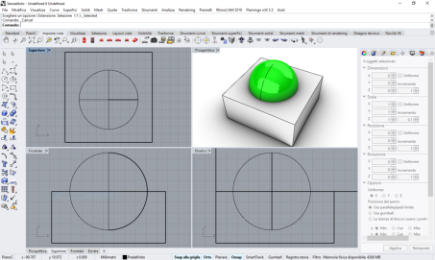
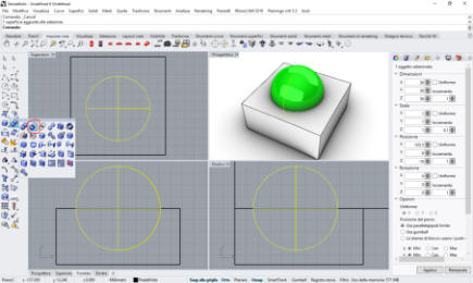
Start
modeling
with
Rhino
3d,
I
create
a
sphere
,
I
divide
it
into
two
parts,
then
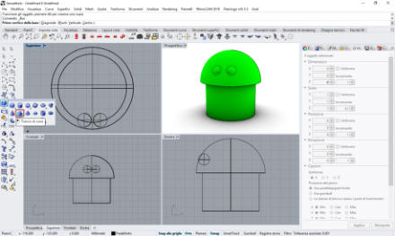
add
one
eye
and
then the other speculate. I also add the body with the legs and the two antennas that will serve to cast the resin.
From virtual to real ..
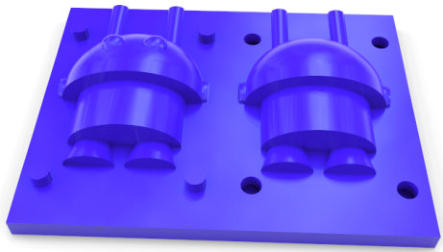
Finally I have reached the practical phase of the realization, the first step is to grind the block of wax to get a positive model for the next phases of the process. Start by saving my file in the .stl format as a three-dimensional object. From the "file" menu of Rhino 3D select "export selection" and choose the .stl format.
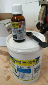
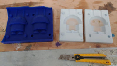
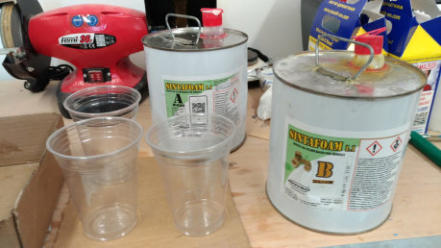
Silicone and catalyst
after milling the wax, the next step is to realize the negative of the two parts that will compose the robot, with the silicone and the catalyst that makes it solid.

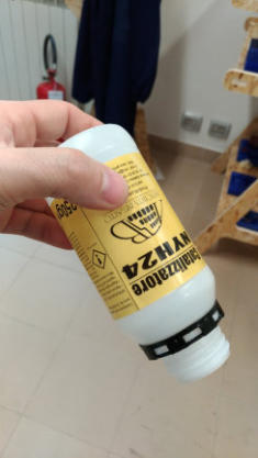
unfortunately the catalyst is over ...
I'll have to wait 10 days to complete!
it's time to complete the work ...
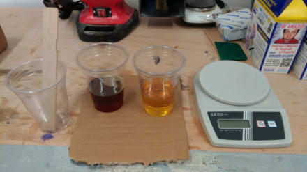
The new catalyst arrives and now I can complete the work, step to weigh the components to be mixed, using the electronic scale I try to be precise to milligram.Finally complete the mold and place it on my wooden shelf to dry.Dry mold
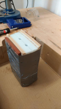
after a whole day I finally extract my mold and prepare it to pour the resin that will make the final model. I have decided to fix two tiles with strong adhesive tape, to prevent the mold from misaligning ... but this choice was made then proved wrong because the strong tension of the tape has misaligned the mold! My inexperience with this technique that I had never done before, has ruined the final piece that once extracted was inaccurate ... but it is my android robot and I love it anyway!


Original Files and Useful Links


Vectric Cut 3D
Cut3D is a dedicated toolpath engine for CNC machining 3D models that have been designed using a 3D CAD or Graphics design product such as AutoCAD, Rhino3D, 3D Studio etc. or scanned using a laser or touch probe device. Cut3D's exceptionally easy to use interface leads you step-by-step through the process of loading a model, setting the size, interactively placing tabs to hold the job in place, calculating single, double or four sided roughing and finishing toolpaths, previewing the results and finally saving the CNC code to run on your machine.Step by step
After starting the 3D vectric software, proceed with the loading of my .stl file and each screen asks to insert the correct values or settings. The first step is to set “orientate and size model” I select “top surface” and “lock xyz ratio” to not deforming model aspect, and “sides to machine” is “top”, now “next” step (click on button “next”).
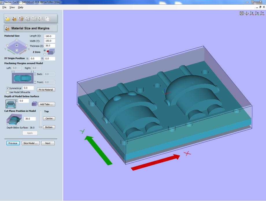
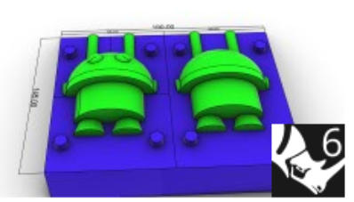
Material Size and Margin
Material size field is filled by me with correct values, 190mm for length, 150 mm for width and 38mm for thickness.The cut plane position in model is set to bottom value.My mistake!
unfortunately I forgot to set " xy origin position " in the lower left corner in the correct way, having left the default value that places the origin at the center of the piece, when I started the processing I had to stop immediately because it started from center of the piece! Obviously I changed the settings and restarted the processing.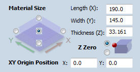

wrong setting!
correct setting!

in this image you can see how the origin of the x and y coordinates is correctly set in the lower left corner


parameters settings and mill drills…
to perform the wax processing it is necessary to set the correct working parameters, starting with the drills for milling. the parameters are: Pass depth = indicates how much the tip drops in every pass Stepover = it is expressed in percentage because it represents the distance between the previous cut and the next one (high percentage means you need more time to mill) Spindle speed = it is measured in r.p.m (revolution per minute), consequently it express the speed related to the spins in 60 seconds Feed rate = indicates the speed of the progress done on the workpiece Plunge rate = indicates the speed at which the tip goes downward (through the material)Calculate the Roughing and Finishing Toolpath
with a left click on the button "calculate" you can generate the work path for the roughing and finishing cycle, these work paths must be saved (click on “Save Toolpaths” button) for the next step, selecting the correct machine type, in my case the "Roland MDX-40 mm" file type “*.rol”
ready to mill ...
The piece of wax must be firmly fixed on the base therefore use of the double-sided adhesive tape (Fig.A) and the attachment to the base of the piece of wax. At this point I can load the previously prepared files(Fig.B) and start processing (Fig.C).Now my model is ready! (Fig.D)
Fig.A
Fig.B
Fig.C
Fig.D