
Assignment:
Design and build a wired &/or wireless network connecting at least two processors.Networking and Communications

/*Master Atmega328p
Networking and Communications
FabLab 2018
Santa Chiara - Siena -Italy
Student: Giuseppe Allocca
Software by :Giuseppe Allocca
Concept: The Master board send a random command
1 for "Led On" or 2 for "Led Off")
*/
// Define Led pins
int powerled = 3;// WHITE LED :Power on
int comled = 2; //BLU LED : Communication sent
void setup() {
Serial.begin(9600);//start Serial
pinMode(powerled, OUTPUT); // set the Pin of the Led as output
pinMode(comled, OUTPUT); // set the Pin of the Led as output
digitalWrite(powerled, HIGH); // Led On
digitalWrite(comled, HIGH); delay(5); digitalWrite(comled, LOW); // Comled: just blink at startup
}
void loop() {
int slave = 1; // number of slave
int command = random(1, 3); // random number will be 1 or 2
digitalWrite(comled, HIGH);// Comled on start communication
Serial.print(command);// send command on serial port
delay(300);
digitalWrite(comled, LOW);// comled off
delay(10000);// wait 10 seconds before to send another random command
}
/*Slave ATtiny 44
Networking and Communications
FabLab 2018
Santa Chiara - Siena -Italy
Student: Giuseppe Allocca
Software by :Giuseppe Allocca
Concept: The Slave board receive a random command
(1 for "Led On" or 2 for "Led Off")
from Master and execute the order.
When the slave is waiting then Blinking
*/
#include <SoftwareSerial.h>// ATtiny 44 don't have the Serial port
int powerled = 2;// define of Power on led
SoftwareSerial mySerial(0, 1); // RX, TX // setup pin for software serial
void setup(){
mySerial.begin(9600);// start software serial
pinMode(powerled, OUTPUT);digitalWrite(powerled, HIGH);//power led on
}
void loop(){
int c = mySerial.read();// read the value on serial rxd pin
if (c==49){// the ASCII value for "1"
mySerial.println("Led On");// print on serial monitor
digitalWrite(powerled, HIGH);delay(8000);// the led stay on for 8 seconds
}
if (c==50){// the ASCII value for "2"
mySerial.println("Led OFF");// print on serial monitor
digitalWrite(powerled, LOW);delay(8000);//the led stay off for 8 seconds
}
else {mySerial.println("NO command");mySerial.print("Valore:");// if the value is not "1" or "2" then print "no command" on serial monitor
mySerial.println(c);// print value
digitalWrite(powerled, HIGH);delay(100);digitalWrite(powerled, LOW);delay(100);// led start to blinking
}
}

Original Files and Useful Links
This is my Master code on Arduino IDE
This is my Slave code on Arduino IDE
Let’s go to Communicate!
Concept:
The Slave board is waiting for command and blink ... so the master board generate at random command, number 1 for led power on and 2 for led power off, and send it to slave by serial port.Final Result:
The video on right side, demonstrates good working of boards and software everything's made by me thanks to knowledges learned by Fablab course.Communication: Serial Asynchronous Interface
Serial interfaces stream their data, one single bit at a time. These interfaces can operate on as little as one wire, usually never more than four. Serial Generalization: Example of a serial interface, transmitting one bit every clock pulse. Just 2 wires required! Asynchronous means that data is transferred without support from an external clock signal. This transmission method is perfect for minimizing the required wires and I/O pins, but it does mean we need to put some extra effort into reliably transferring and receiving data.

This is my first Idea to develop for networking week
My Problem Reading the serial data .... 1 = 49 !!!
When I try the code for the first time, I can not see the expected value on the Arduino serial monitor. My main code simply sends a number to communicate the command, only 1 or 2. This operation seems to be really easy and I do not understand why it does not work properly. I check the code but it seems correct so .. I try to connect the txd pin of the master card to the Arduino serial monitor and ... the correct value is on the screen! The problem exists from the master to the slave, to understand why ... I make a temporary change to my master code and generate a wide range of random numbers and the slave code that prints all the value received from the master to the Arduino serial monitor, so the text is on screen and I understand: it is the ASCII code !!!What is the ASCII Code?
The American Standard Code for Information Interchange (acronym: ASCII) is a character-encoding scheme based on the ordering of the w:English alphabet. ASCII codes represent text in computers, communications equipment, and other devices that use text. Most modern character-encoding schemes, which support many more characters than did the original, are based on ASCII. At this point I make the changes on the master and slave code, when the master transmit the random command send a value in ASCII code, so ... 1=49 and 2=50 this is the solution! After the changes on the Arduino codes everything works good. The changes in the Arduino slave code concern the "IF" control and the serial value read: int c = mySerial.read();// read the value on serial rxd pin if (c==49){// the ASCII value for "1" if (c==50){// the ASCII value for "2"
The Slave

The Master


Wired Communication from Master Board to Slave board
To complete the assignment of this week I will try to use the serial communication protocol and two of my cards made in fablab by me.The correct wiring:
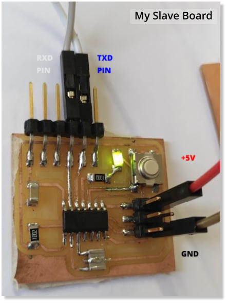
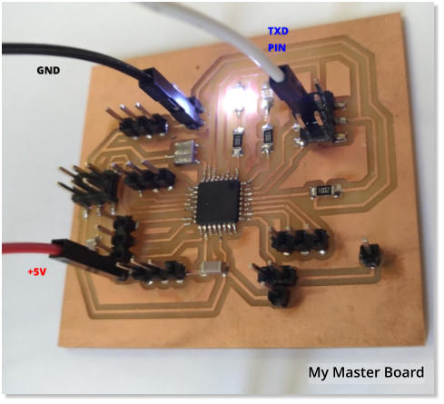
Studying the serial protocol I understood two basic rules that I have to respect when I physically connect my two cards: 1- The TXD pin of the Master must be connected to the RXD pin of the slave and vice versa. 2- The two cards must have the GND in common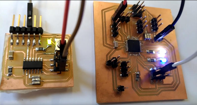
SLAVE BOARD
MASTER BOARD
+5V
+5V
GND
GND
TDX
RDX

Develop the code for Master and Slave
Now
I
have
to
write
a
software
code
for
my
boards,
using
Arduino
IDE
and
integrated
serial
monitoring
tools,
I
can
do
it
more
easily.
In my code I need the
RANDOM
function to generate commands and the
SERIAL
function to write and read the value.
I think it's a good idea to read the documentation of these functions in the
Official Arduino reference guide
.
Below is the information of the official guide, which I will study to learn how to use the two functions.
random()
[Random Numbers] Description The random function generates pseudo-random numbers. Syntax random(max) random(min, max) Parameters min - lower bound of the random value, inclusive (optional) max - upper bound of the random value, exclusive Example Code: // print a random number from 10 to 19 randNumber = random (10, 20); Serial.println(randNumber);Serial
[Communication] Description Used for communication between the Arduino board and a computer or other devices. All Arduino boards have at least one serial port (also known as a UART or USART): Serial. It communicates on digital pins 0 (RX) and 1 (TX) as well as with the computer via USB. Thus, if you use these functions, you cannot also use pins 0 and 1 for digital input or output. You can use the Arduino environment’s built-in serial monitor to communicate with an Arduino board. Click the serial monitor button in the toolbar and select the same baud rate used in the call to begin().Serial.begin()
Description Sets the data rate in bits per second (baud) for serial data transmission. For communicating with the computer, use one of these rates: 300, 600, 1200, 2400, 4800, 9600, 14400, 19200, 28800, 38400, 57600, or 115200. You can, however, specify other rates - for example, to communicate over pins 0 and 1 with a component that requires a particular baud rate. An optional second argument configures the data, parity, and stop bits. The default is 8 data bits, no parity, one stop bit. Syntax Serial.begin(speed) Serial.begin(speed, config) Example Code: Serial.begin(9600); // opens serial port, sets data rate to 9600 bpsSerial.read()
Description Reads incoming serial data. read() inherits from the Stream utility class. Syntax Serial.read() Example Code: value= Serial.read();Serial.write()
Description Writes binary data to the serial port. This data is sent as a byte or series of bytes; to send the characters representing the digits of a number use the print() function instead. Syntax Serial.write(val) Serial.write(str) Serial.write(buf, len) Example Code: Serial.write(45); // send a byte with the value 45Start to Write the Code
I have the elements of programming to write my "wiring" code in Arduino IDE and start to write for the Master and Slave software.

To explain exactly what serial communication is, I do not want to invent personal definitions, so I use the information on the Sparkfun website: