
Assignment
group assignment - actuate and automate your machine - document the group project and your individual contributionMechanical Design

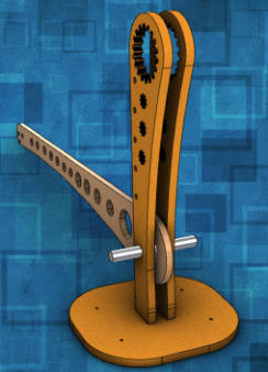

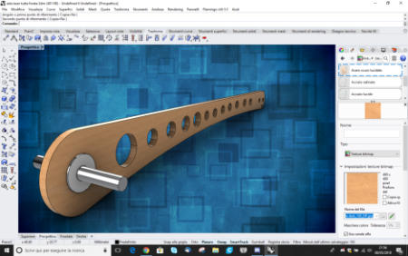


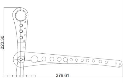


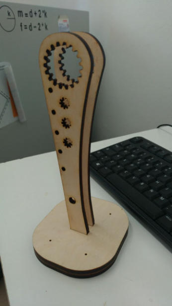

I decided to redesign the lever and the support with the same software. In this new design, I paid attention to create a more stylized but above all thin
structure of the lever to facilitate its movement. (Fig.D). In addition, I have considered several holes in the lever and support allowing a further lightening
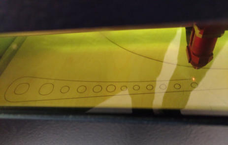
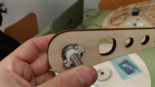
of the structure. Once the design was ready, I decided to cut the different parts of it pieces with the laser machine. The lever would move thanks to a steel
pin inserted inside a fulcrum through a bearing (Fig.E).
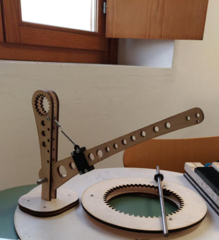
Now I have therefore cut all the pieces with the laser machine and I have assembled them together, the final result should be that of the 3d model.

Spring hooking
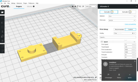
The spring must be hooked very firmly. For this reason I created a spring support to be fixed on the lever. I made the drawing in 3D with and I print it with the ultimaker 2 of our fablabThe Idea and the Design
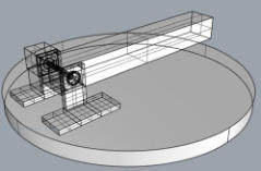
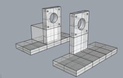
Together with my classmates, Antonio and Eleonora, we decided to build a catapult! Our idea is to create an object not too difficult to build, but not trivial, taking care to improve our skills. The work will be subdivided like this: - Eleonora will make the rotating base, which will allow the catapult to be oriented. - Antonio will build the central part that will adjust the height by blocking the lever and the control software. - I will build the mechanism of the lever. The head of the catapult is a simple spoon, we decided to omit it, we can insert it at the end. More information on group work can be found on the dedicated page, the link is at the bottom of this page. Just as an example, but it helps me to reflect on the work, with the "Rhino 3d software" I designed the structure of the catapult (Fig.A) made of a lever, and its support (Fig. B) An engine would allow the movement of the lever and would be incorporated into the lever through the dowels. (Fig C). However this was not a good idea because in this way the engine would brake the lever.interlocking and flowing thread
to load the spring and to have the wire in tension it is necessary to have a support where the thread can slide. It is necessary to create a joint in 3d and place it in the upper part of the rod. This will allow me to connect the motor that will stretch the spring which in turn will give the boost to the auction.
Ready for the engine!
The mechanical part is now ready and working, at this point I have to implement the engine that stretches the spring and triggers the catapult lever up. Let's move on to the next phase of the project, with the electronics and the software part of the machine control.
Fig.A
Fig.B
Fig.C
Fig.D
Fig.E

