

Assignment:
Write an application that interfaces with an input &/or output device that you madeInterface and Application Programming
Software choise…
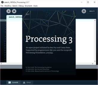
To complete this assignment, first of all I have to evaluate which software to use for the development of the program that will manage my hall sensor board 2. Personally I had started studying java as a programming language two or three months before starting the course at fablab. I was advised by Pietro Rustici to use the development software called processing. After visiting the official website, I became convinced that was the right one to use to create my application.
My Hall Sensor board 2!
Idea
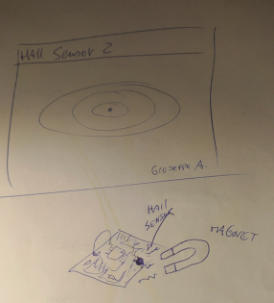
I would like to see my card that sends the data detected by the magnetic sensor to the computer and that these data were graphically displayed as a magnetic field ... a sort of ellipse that changes size as the data changes ... Obviously I've never realized a something like that before the fablab ... I think it will be complicated ... but I want to complete this assignment because it's really fascinating to see how objects can dialogue and exchange information. Let's start this new challenge!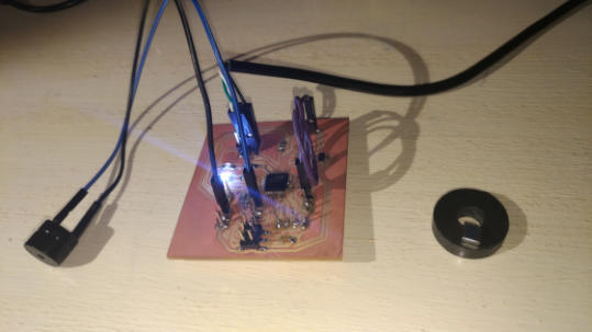


where to start?
To start…I read the command index and the syntax to use them correctly, this required hours of study. The most useful strategy to learn quickly was to upload the sample files and understand how they worked. I had clear in mind what I had to do , so I looked for examples on the serial port, about the graphic commands to trace ellipses, and also how to manage the cycles and the code conditions.
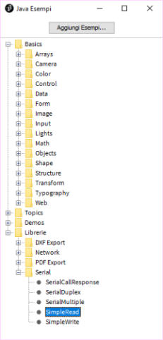


Sample
of
simple
read
data
from
serial
port
and
how
create
shape
primitives,
in
this
case
my
interest
is
for
ellipse
shape
to
draw
the
magnetic
signal.
Ready to write the code...
after some hours past to modify example codes ,now I can try to write the code of my program.Define the variables, the window resolution and colors of text and graphics elements,also is very important to import the serial library to establishing communication with my board.
/* Graphic Visualization of Hall Sensor 2 board data.
the data are sent via serial communication port.
written by Giuseppe Allocca 2018
Fablab Santa Chiara Siena Italy
*/
import processing.serial.*;
Serial myPort; // Create object from Serial class
int val; // Data received from the serial port
void setup()
{
size(800, 600);//windows 800x600
background(0);//black color
String portName = Serial.list()[0]; // select the first com in system
myPort = new Serial(this, portName, 9600);
}

how to draw the ellipse?
The support that is provided to the users of the processing software is very good. The reference guide of the programming language is well organized, so it is easy to find the command to create the ellipses that interests me.
void draw()
{
background(0);
textSize(32);
fill(255);
text("Hall Sensor 2 ", 32, 42);
textSize(18);
fill(0,0,255);
text("Giuseppe Allocca * FabLab 2018 *",250,568);
val = myPort.read();// read value from serial port
stroke(255, 0,0); fill(0);ellipse(400, 300, val*10, val*5);// draw red ellipse in the
center of the screen
}
the second part of my java code
To complete the program it is necessary to draw on the screen the ellipse which must change its size in sync with the data it receives from the magnetic sensor.I do not want a full ellipsis on the screen, but only the outline ... the command to define the outline color is "stroke"..
By monitoring the values arriving on the serial port, I notice that they are low and then multiply them by 10 on the x axis and 5 on the y axis, this
allows me to maintain an elliptical appearance of the graphics that would otherwise be a circle.
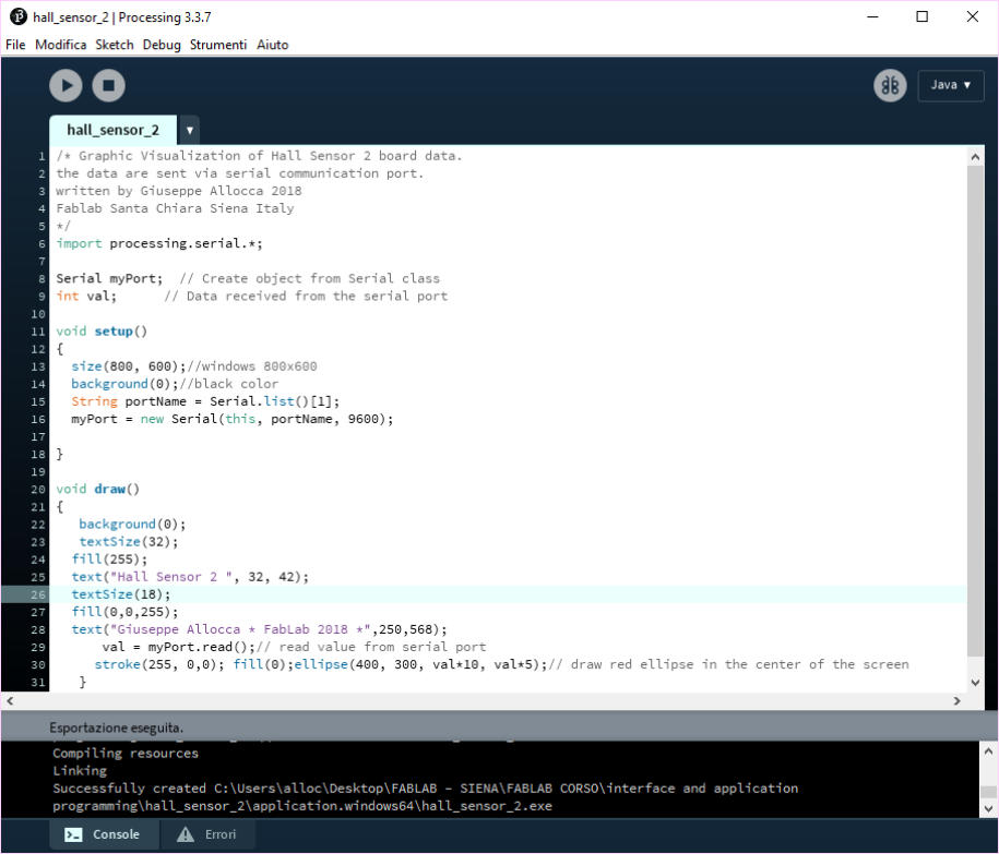
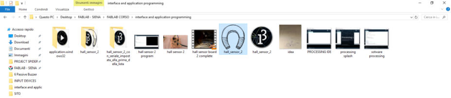
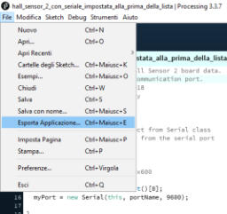
this is my complete code and below the running program and its icon that I customized, after exporting the executable file, from the file menu select
export application.
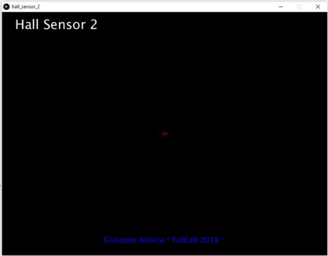

The software is ready and works well!
I am very satisfied with the result which is exactly how I imagined it, even though I worked for 15 hours! Please , play the video to see the final result…Original Files and Useful Links
Hall Sensor 2.1
Upgrade: external resonator 20.000 Hrz Firmware upgrade: serial port baud rate ok software upgrade: more ellipses are drawed on the screen and "no signal "are detected and wrote on display.
/* Graphic Visualization of Hall Sensor 2 board data.
the data are sent via serial communication port.
written by Giuseppe Allocca 2018
Fablab Santa Chiara Siena Italy
*/
import processing.serial.*;
Serial myPort; // Create object from Serial class
int val; // Data received from the serial port
void setup()
{
size(800, 600);//windows 800x600
background(0);//black color
String portName = Serial.list()[0];
myPort = new Serial(this, portName, 9600);
}
void draw()
{
background(0);
textSize(32);
fill(255);
text("Hall Sensor 2 ", 32, 42);
textSize(18);
fill(0,0,255);
text("Giuseppe Allocca * FabLab 2018 *",250,568);
val = myPort.read();// read value from serial port
if (val == -1){ textSize(32); fill(0,255,0);text("No Magnetic Signal Detected",150,300);}
if (val!= -1) {
float casual = random (val);
stroke(255,0,0); fill(0);ellipse(400, 300, 12*casual,6*casual);// draw red ellipse in the center of the screen,ellipses are mapped to the serial stream
}}
UPGRADE!
Processing Splash screen
Name
ellipse()
Examples

ellipse(56, 46, 55, 55);
Description
Draws an ellipse (oval) to the screen. An ellipse with equal width and height is a circle. By default, the first two parameters set the location,
and the third and fourth parameters set the shape's width and height. The origin may be changed with the
ellipseMode()
function.
Syntax
ellipse(
a
,
b
,
c
,
d
)
Parameters
a
float: x-coordinate of the ellipse
b
float: y-coordinate of the ellipse
c
float: width of the ellipse by default
d
float: height of the ellipse by default
Returns
void
Related
ellipseMode()
arc()
My Error:Digital pin is not Analogic pin!!!
My First board named “Hall sensor 1” have a issue of development because the data pin of hall sensor Is connected to digital pin of ATmega 328p
microcontroller.This is a mistake and my "hall sensor" software can not read the value.Another error is that: I don’t connected the tdx and rdx pins of
serial interface … so I need to remake the board and create a new board …that is “Hall Sensor 2”

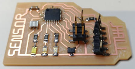
My first electronic Board : with the ground connector line is writing text "Hall
sensor" that is very cool for me!

wrong pin connected

