
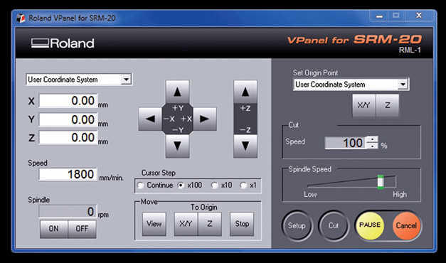

SRM-20 Compact Milling Machine
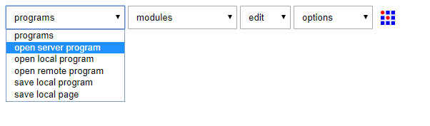
file to open?
image
function
motion detect
palette mask raster
palette mask vector
iterate
z theta scan
machines
Epilog
cut png
cut svg
cut svg connect
G-code
mill 2D png
Roland
mill
MDX-20
PCB
SRM-20
PCB
PCB svg connect


file to open?
apa
node
character
convert
in out
parse
variable
connect
svg
ExtractFaces
PCB
SelectFace
control
slider
convert
rgba
jpg
png
svg
array
image
event
delay
generate
pause
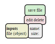
file
save

FabISP Production and programming
The FabISP is an in-system programmer for AVR microcontrollers, designed for production within a FabLab. To Make an in-circuit programmer by milling the PCB ,I Download the Board Files and Mill the Board with Roland SRM-20 Milling Machine. this is the choice model: FabOptimus (R_pullup=1.5K) http://fab.cba.mit.edu/classes/863.16/doc/tutorials/FabISP/FabISP_Demystified.htmlElectronics Production


FabISP: Programming
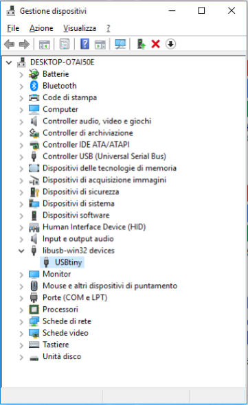
I been followed the tutorial on : http://archive.fabacademy.org/archives/2016/doc/programming_FabISP.html 1) Download the software :http://winavr.sourceforge.net/download.html 2) Download the Fabisp drivers https://learn.adafruit.com/usbtinyisp/drivers 3) Download the FabISP Firmware :http://academy.cba.mit.edu/classes/embedded_programming/firmware.zip 4) Plug in another FabISP or USBtiny programmer 5) Install the drivers:
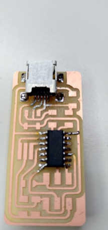
This is a ‘hero shot’ of my board!
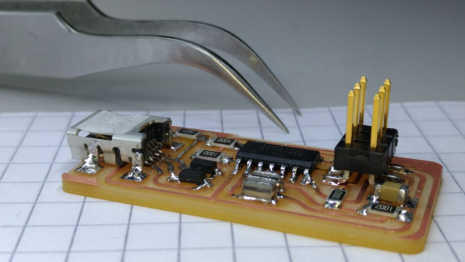
My Milled and cleaned FabISP Board
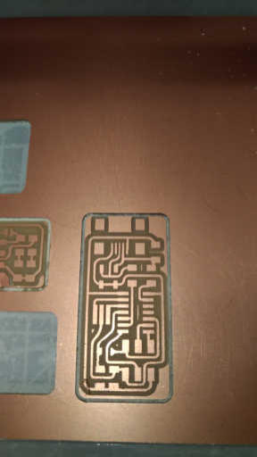
Circuit Board Traces
I Download the traces png and Mill using the fab modules and a 1/64" bit. Design Files : http://fab.cba.mit.edu/classes/863.16/doc/tutorials/FabISP/FabISP_Demystified_files/FabOptimus_Traces.pngBoard Outline
I Download the outline png and Mill using the fab modules and a 1/32" bit. Design Files : http://fab.cba.mit.edu/classes/863.16/doc/tutorials/FabISP/FabISP_Demystified_files/FabOptimus_Outline.png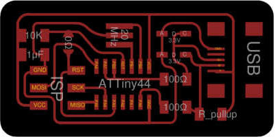
Generate file for milling machine
From site : http://mods.cba.mit.edu/
now connect output and input
After click on “Calculate” button the output file is generated as Roland mill (.rml) format, ready to milling.
I repeated same steps also for Outlines.png, but with mill traces 1/32. Now I copied my two .rml files in a USB pen drive and I transfered them into
the PC connected to the Roland milling machine.

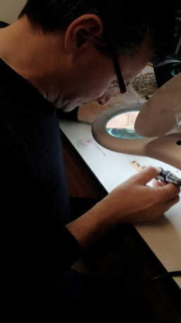
Soldering
it's time to take action! I write a list of components (bom) and proceed to solder them to the board, start from mini usb plug and ATTiny 44.


after three hours of work ... finally I finish but some parts do not like me..then I check all the components and they look set well…now I proceed
with the programming phase.
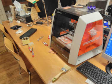
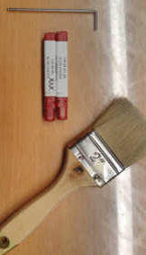

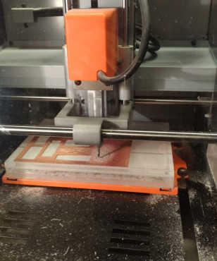
Setup of milling machine
to proceed to the milling of the pcb board, I clean the working plane and load the 1/64 bit for the tracks, then insert the parameters for the machining, gauge the z axis and set the origins of the piece to be mill.I had no problem.When it's finished I clean the pcb board.below is the programming process in windows powershell like administra-
tor, in the firmware folder:
PS C:\Users\UTENTE\Desktop\FAB ACADEMY 2018\FAB ISP OPTIMUS\firmware\fabISP_mac.0.8.2_firmware> .\makefile clean PS C:\Users\UTENTE\Desktop\FAB ACADEMY 2018\FAB ISP OPTIMUS\firmware\fabISP_mac.0.8.2_firmware> make hex avr-gcc -Wall -Os -DF_CPU=20000000 -Iusbdrv -I. -DDEBUG_LEVEL=0 -mmcu=attiny44 -o main.elf usbdrv/usbdrv.o usbdrv/usbdrvasm.o usbdrv/oddebug.o main.o rm -f main.hex main.eep.hex avr-objcopy -j .text -j .data -O ihex main.elf main.hex avr-size main.hex text data bss dec hex filename 0 2016 0 2016 7e0 main.hex PS C:\Users\UTENTE\Desktop\FAB ACADEMY 2018\FAB ISP OPTIMUS\firmware\fabISP_mac.0.8.2_firmware> make fuse avrdude -c usbtiny -p attiny44 -U hfuse:w:0xDF:m -U lfuse:w:0xFF:m avrdude: AVR device initialized and ready to accept instructions Reading | ################################################## | 100% 0.02s avrdude: Device signature = 0x1e9207 avrdude: reading input file "0xDF" avrdude: writing hfuse (1 bytes): Writing | ################################################## | 100% 0.02s avrdude: 1 bytes of hfuse written avrdude: verifying hfuse memory against 0xDF: avrdude: load data hfuse data from input file 0xDF: avrdude: input file 0xDF contains 1 bytes avrdude: reading on-chip hfuse data: Reading | ################################################## | 100% 0.02s avrdude: verifying ... avrdude: 1 bytes of hfuse verified avrdude: reading input file "0xFF" avrdude: writing lfuse (1 bytes): Writing | ################################################## | 100% 0.02s avrdude: 1 bytes of lfuse written avrdude: verifying lfuse memory against 0xFF: avrdude: load data lfuse data from input file 0xFF: avrdude: input file 0xFF contains 1 bytes avrdude: reading on-chip lfuse data: Reading | ################################################## | 100% 0.00s avrdude: verifying ... avrdude: 1 bytes of lfuse verified avrdude: safemode: Fuses OK avrdude done. Thank you. PS C:\Users\UTENTE\Desktop\FAB ACADEMY 2018\FAB ISP OPTIMUS\firmware\fabISP_mac.0.8.2_firmware> make program avrdude -c usbtiny -p attiny44 -U flash:w:main.hex:i avrdude: AVR device initialized and ready to accept instructions Reading | ################################################## | 100% 0.02s avrdude: Device signature = 0x1e9207 avrdude: NOTE: FLASH memory has been specified, an erase cycle will be performed To disable this feature, specify the -D option. avrdude: erasing chip avrdude: reading input file "main.hex" avrdude: writing flash (2016 bytes): Writing | ################################################## | 100% 2.23s avrdude: 2016 bytes of flash written avrdude: verifying flash memory against main.hex: avrdude: load data flash data from input file main.hex: avrdude: input file main.hex contains 2016 bytes avrdude: reading on-chip flash data: Reading | ################################################## | 100% 1.37s avrdude: verifying ... avrdude: 2016 bytes of flash verified avrdude: safemode: Fuses OK avrdude done. Thank you. avrdude -c usbtiny -p attiny44 -U hfuse:w:0xDF:m -U lfuse:w:0xFF:m avrdude: AVR device initialized and ready to accept instructions Reading | ################################################## | 100% 0.01s avrdude: Device signature = 0x1e9207 avrdude: reading input file "0xDF" avrdude: writing hfuse (1 bytes): Writing | ################################################## | 100% 0.02s avrdude: 1 bytes of hfuse written avrdude: verifying hfuse memory against 0xDF: avrdude: load data hfuse data from input file 0xDF: avrdude: input file 0xDF contains 1 bytes avrdude: reading on-chip hfuse data: Reading | ################################################## | 100% 0.00s avrdude: verifying ... avrdude: 1 bytes of hfuse verified avrdude: reading input file "0xFF" avrdude: writing lfuse (1 bytes): Writing | ################################################## | 100% 0.00s avrdude: 1 bytes of lfuse written avrdude: verifying lfuse memory against 0xFF: avrdude: load data lfuse data from input file 0xFF: avrdude: input file 0xFF contains 1 bytes avrdude: reading on-chip lfuse data: Reading | ################################################## | 100% 0.02s avrdude: verifying ... avrdude: 1 bytes of lfuse verified avrdude: safemode: Fuses OK avrdude done. Thank you.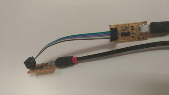
obviously, the two cards must be connected with the pins in the same direction to match!
it seems that everything went well!
now I can test the pcb card, then connect the usb cable to the mini usb port of the card and connect it to the computer….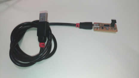
I thank my classmate Dario Bernabini for some photos I took from his page because I missed them.
http://fab.academany.org/2018/labs/fablabsiena/students/dario-bernabini/index.html