
Electronics Design
Assignment:
redraw the echo hello-world board
add (at least) a button and LED (with current-limiting resistor) check the design rules, make it, and test it extra credit: measure its operation extra extra credit: simulate its operation To complete the assignment of this week is necessary to know the basic fundamentals of modern electronic and understand how the single components works.I think is better to analyze the electronic board and try to understand what each component does it do.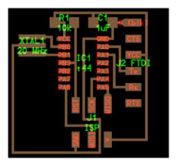


Echo Hello-world board
Components list :
1x ISP
1x ATtiny44
1x 1uF capacitor
1x 10kΩ resistor
1x 20MHz resonator
1x J2 FTDI USB interface data
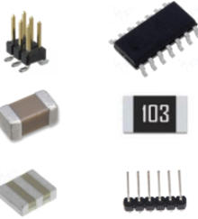
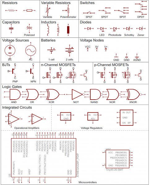
Resistors
The most fundamental of circuit components and symbols! Resistors on a schematic are usually represented by a few zig-zag lines, with two terminals extending outward. Schematics using international symbols may instead use a featureless rectangle, instead of the squiggles.
Capacitors
There are two commonly used capacitor symbols. One symbol represents a polarized (usually electrolytic or tantalum) capacitor, and the other is for non-polarized caps. In each case there are two terminals, running perpendicularly into plates.
Crystals and Resonators
Crystals or resonators are usually a critical part of microcontroller circuits. They help provide a clock signal. Crystal symbols usually have two terminals, while resonators, which add two capacitors to the crystal, usually have three terminals.
Integrated Circuits
Integrated circuits accomplish such unique tasks, and are so numerous, that they don’t really get a unique circuit symbol. Usually, an integrated circuit is represented by a rectangle, with pins extending out of the sides. Each pin should be labeled with both a number, and a function.
Headers and Connectors
Whether it’s for providing power, or sending out information, connectors are a requirement on most circuits. These symbols vary depending on what the connector looks like.
Diodes
Basic diodes are usually represented with a triangle pressed up against a line. Diodes are also polarized, so each of the two terminals require distinguishing identifiers. The positive, anode is the terminal running into the flat edge of the triangle. The negative, cathode extends out of the line in the symbol (think of it as a - sign).There are a all sorts of different types of diodes, each of which has a special riff on the standard diode symbol. Light-emitting diodes (LEDs) augment the diode symbol with a couple lines pointing away.

Switches
Switches exist in many different forms. The most basic switch, a single-pole/single-throw (SPST), is two terminals with a half-connected line representing the actuator (the part that connects the terminals together).
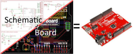
Redraw the echo hello-world board: Eagle Software
To design the new board I must use the Eagle software.This is a very famous software to produce PCB board, now I start to learn how use it to make my board, let's go to know the program! First of all, I proceed to download the program at the link follow: https://www.autodesk.com/products/eagle/free-download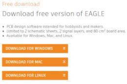


Icon of Program
Double ambient :
Eagle software works with dual concept : 1- Schematic ambient to design the logical connection of all components. 2- Board ambient to design connections from and to all elements in schematic, and control the features of final pcb board.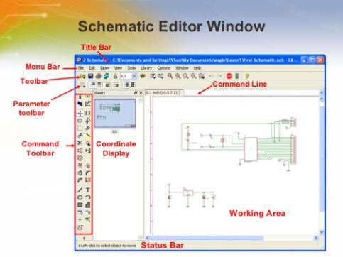
IMPORT FAB LIBRARIES IN EAGLE
To work correctly by available fablab electronics components , we need download the fab.library for Eagle and I found this file at https://github.com/Academany/FabAcademany-Resources/blob/master/files/fab.lbr after download, the file must be moved from download folder to C:\EAGLE 8.6.3\lbr folder to be accessible.There are many other additional libraries for eagles, among the most famous are the sparkFun libraries, you can download them from this address.https://github.com/sparkfun/SparkFun-Eagle-Libraries

so ...we start to create the schematic
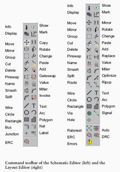
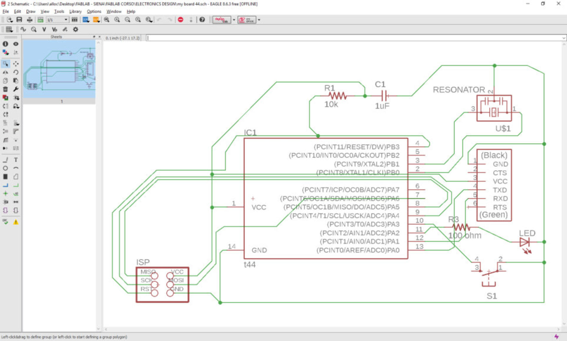
To start to add the components in the schematic I click on the "add" icon and select the fab library from the library list in the window, also seek the ATtiny 44 and double mouse click to select and confirm it. In this way all components are add to schematic and the pins are been connected by me using the "net" command from toolbar. In according with assignment of week the led and button are included. The result is in the next screenshot.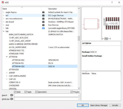


go to Board screen..
now I can work in the board section and first of all to set the correct parameters for grid and DRC in tools menu ,wire, pad, via, smd, everything 16 mil.
using
“route”
command,
all
pins
are
been
connected,
with
particular
attention
to
look
for
“x”
symbol
when
the
line
is
correctly
connected,
eagle
helped
me in this action …to be honestly in the very first time using eagle software
I don't understand this important detail and try one hundred lines!!!
the board is ready to milling....
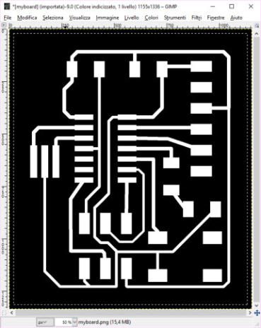
I need the graphic file to generate a file for Roland milling machine.Using the "file" menu and selecting export command, the window of png file save appear and I can set the parameters like 1000 dpi and monochrome format and Just save the file.

Outline file to milling the external of board
in order to obtain the external outline graphic for milling, is necessary to use one graphical software able to pixel manipulation, in this case I use the Gimp program to create a extended area around the image to obtein a black frame of 20 pixel they will be a line of cutting for milling.

Open
png
file
of
board
previously
saved
by
eagle,
select
all
of
image
and
reduce
the
selction of 20 pixel from bord
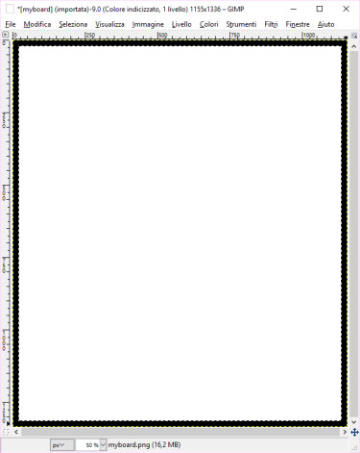
now
I
clean
the
selection
area
with
canc
key
in
my
keyboard
and
only
black
frame
remain
in
the
screen,
at
this
point
the
image
of
frame
can
be
saved
in
project
directory.I
have
both
images
to
generate
a
Roland
files
for
milling,
I
do
it
using
web
application
named
Fab
moduls, learned in the "electronics production" week.


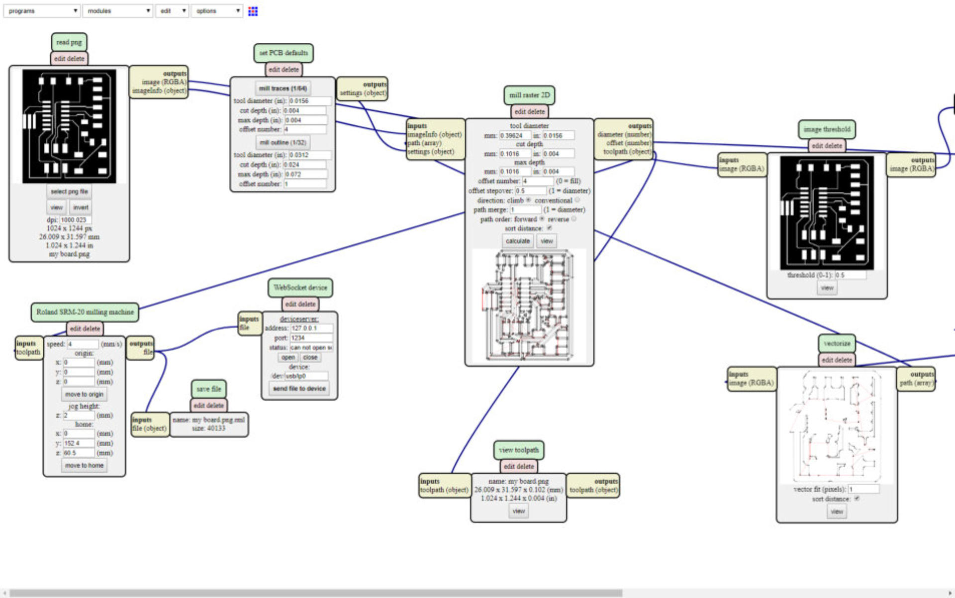
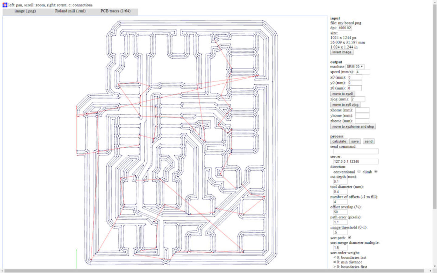
Milling the Board
I have all the .rml files to work with roland SRM-20 machine and start to milling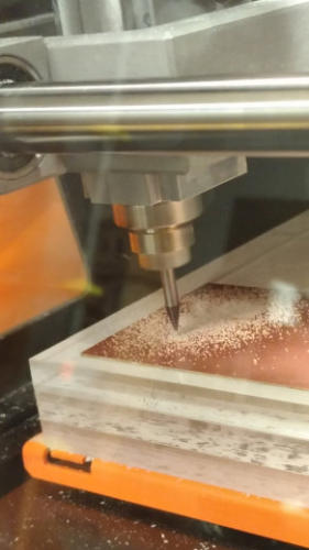
Part list to soldering
Exported from my board 44.brd at 12/03/2018 19:14 EAGLE Version 8.7.0 Copyright (c) 1988-2018 Autodesk, Inc. Assembly variant: Part Value Package Library Position (mm) Orientation C1 1uF C1206FAB fab (48.0064 -45.2) R0 FTDI FTDI-SMD-HEADER 1X06SMD fab (54.4 -51.2) R0 IC1 t44 SOIC14 fab (42.7936 -54.8) R270 ISP 2X03SMD fab (42.8 -66.4) R270 LED LED1206FAB fab (54.4672 -62.1472) R359.5 R1 10k R1206FAB fab (40.4 -45.2) R180 R3 100 ohm R1206FAB fab (50.7648 -58.1856) R270 S1 6MM_SWITCH fab (52.4256 -67.8688) R180 U$1 RESONATOR EFOBM fab (35.4538 -56.3808) R0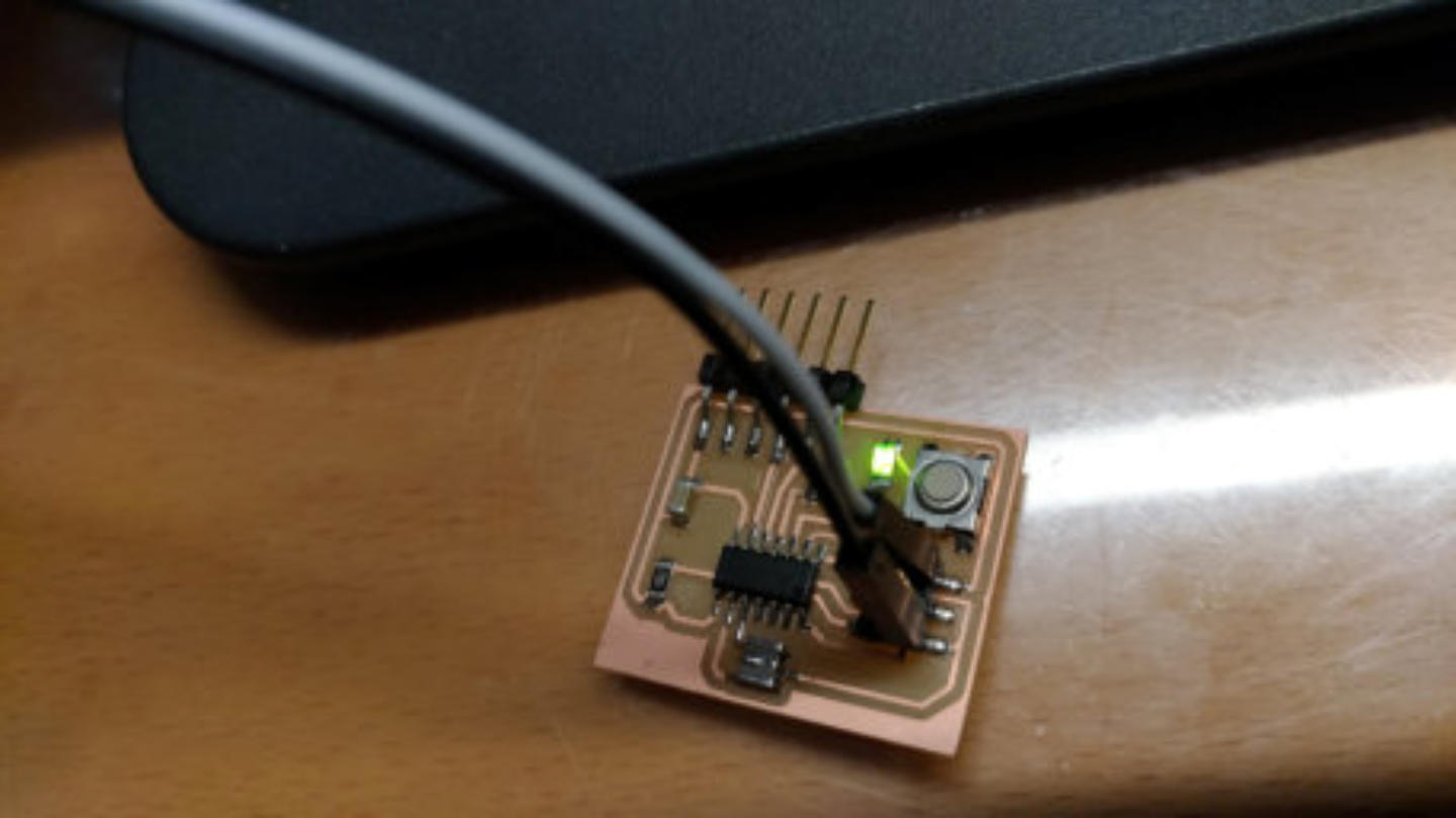


I TESTED IT !
In the week of “embedded programming” I have tested the board made in this week and everything work so good!!! When button is pressed the led turn on, the board need power 5v from isp cable connected to isp fab programmer that I made in the past weeks.Fundamental schematic symbols:
Start
to
soldering:
AVR
Micro-controller
ATtiny 44
Yellow led is fixed to board
The next is the resistor for led
The Roland Machine is ready to work
The x, y, and z axis are been configured using the control panel
The Button arrive..
The Capacitor is fixed
Another resistor and resonator 20.000 Hz
ISP and FTDI Header… all pieces are soldered
My Board is complete

