
Computer-Controlled Machining
Assignment
Make something big!
…can I build a wooden house? maybe ... of 3 floors? jokes aside ... I had no idea to design something non-trivial ... then ..think…think…think…..
I lit a light bulb ...IDEA!
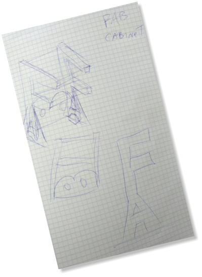

FAB Cabinet!
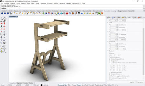
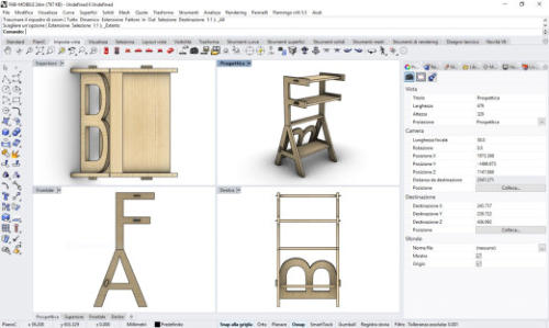
immediately start working to design the fab-cabinet through a 3d program, I chose to work with Rhino 3D because I like it a lot and I think it's a very powerful software.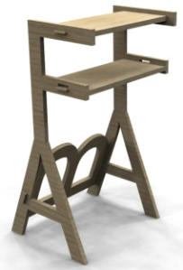
Let’s Start to modeling!
using the tool for the text, insert the letters F A B giving an extrusion of 18 mm like the wooden board that I will use to cut the pieces. I place the letters F and A and unite them with a Boolean operation ... then I rotate the letter B and place it on the back side. The linear shelves are easy to make, with the instrument for rectangular solids I create the shelves of the same thickness. To give a more realistic appearance, I look for a wooden texture on the net and the load in the rhino program as texture of the material.
It’s nice …but…
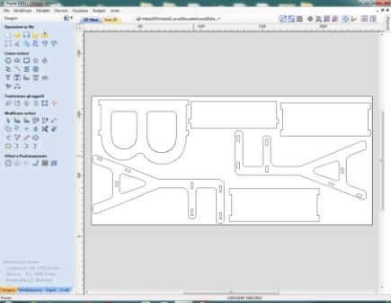
for the machining with the numeric control machine, I would prefer to have a softer, more rounded shape, the work is better with rounded profiles. Anyway, I am going to make a restyling of the furniture cabinet. I plan to connect all the corners to 90 degrees and also the internal parts to be excavated, such as B and A, all rounded up.The result satisfies me a lot, so I move on to prepare the files for the processing. First of all I need the pieces to be cut to be on the same two-dimensional plane, so I redraw the parts with the measurements I have determined.When the work is finished, the file to be exported looks like this:

The
file
is
saved
in
the
DXF
format
and
must
be
transferred
to
a
pen-drive
because
the
shopbot
that
cuts
the
wood
is
in
the
carpentry,
I
transfer
the
file
and
after
making arrangements with the staff I go to the carpentry for processing.
TEXTURE


Woodworking, wood, milling program.
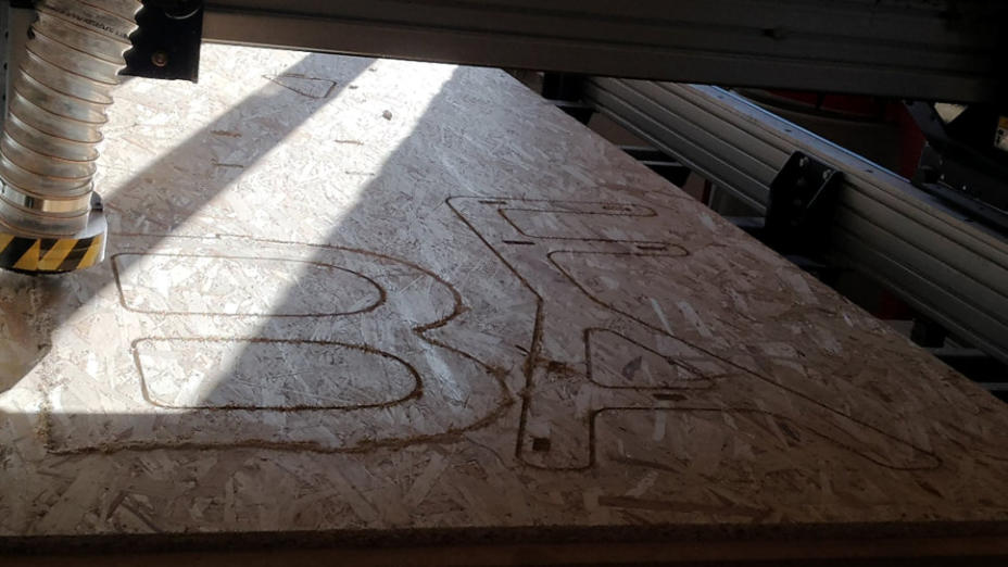
The machine is the Shopbot Alpha, very large and extremely powerful but also dangerous, the safety rules must be scrupulously respected, then wear the protections and I go to measure the wooden panel (250x125 cm and my .dxf file working on 230x105 cm) that I will have to fix on the top of plane of machine.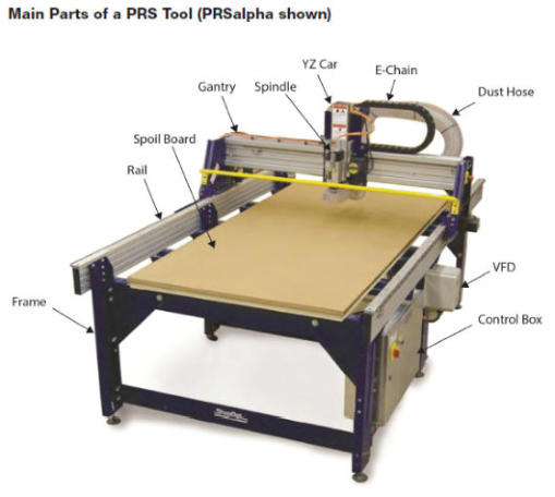


to
prepare
the
dxf
file
and
make
it
suitable
for
processing,
you
must
use
the
program
Vectric
Aspire.
Once
the
program
has
started,
load
my
file
and
verify
that
there
are
no
breakpoints
in
the
drawing
profile.
There
are
open
vectors
and
so
you
have
to
close
those
paths,
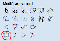
I
do
it
using
the
appropriate
function of the program.
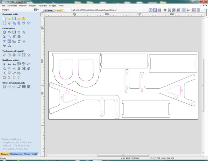
I Selected the open vectors and combine them with the specific tool.
The same operation must be repeated for the external profile, if there are open vectors.
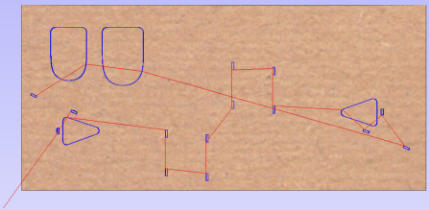
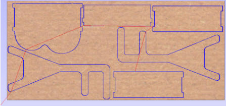
create a path
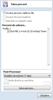
To perform the machining of both the external part and the internal holes and openings, it is necessary to create work paths and save them.


The internal and external paths are two separate
operations to be performed in two stages


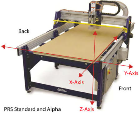
Shopbot settings of x,y,z axis (from the official manual)
Like the small roland milling machine that we at the fablab use for electronic boards, even the bulky shopbot needs to reset the axes. The x and y axis are simple to set, while the z axis needs a dedicated procedure.And now you can cut it!


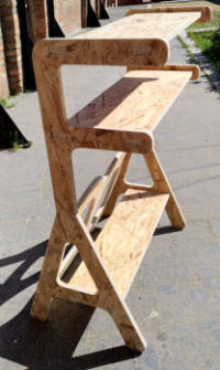
My 3D model
My Real object
Don't you find it
a good job?


Original Files and Useful Links
My mistake...
Taken from the enthusiasm .. I started to immediately model my object in 3d creating the assembly to see how it would be the final result.Then I realized that for processing I needed a 2d file, in .dxf format to process the work paths useful for the wood milling machine. After several attempts to break down my 3d model that I had extruded and combined with Boolean math operations, I realized that it took a long time and it would be much faster to do it all over again. The lesson I learned is that : you have to start from the 2d file for processing, save the two-dimensional file and then extrude the polygons to create and compose the 3d object.
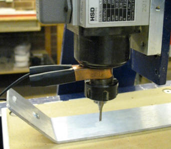
Ground Clip
Z zero Plate
Shopbot is cutting the panel
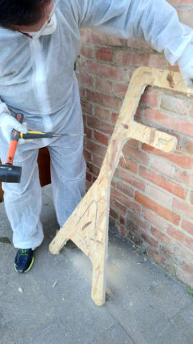
The
cutted
panel,to
hold
up
it
it's
a
good
idea
to
place
the
pieces
of
wood under bottom.
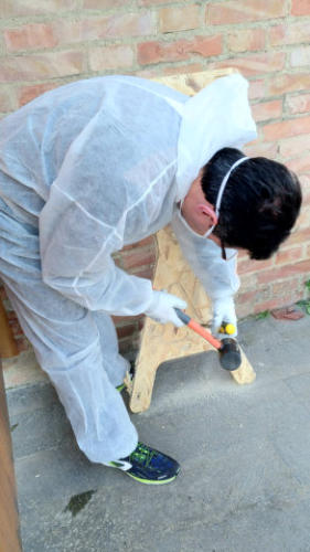
to
remove
the
scraps,
I
use
a
chisel
and
a
hammer.
Small
strokes,
but
strong.
it
is
useful
to
wear
protective
glasses,
because
some
wooden
scabbards could fly away.
Front View
Side View
Back View
the wood pressed panels
My safety kit

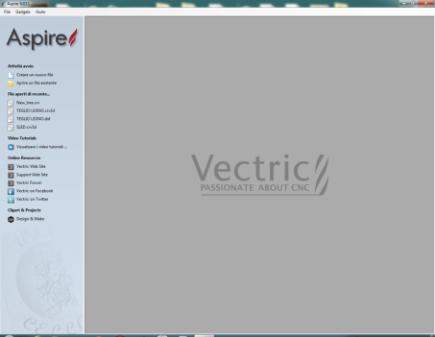
Splash screen of Vectric
My imported .dxf file
The FabLab’s Shopbot
The tool to Fix Open Vectors
The selected open vectors
The External Path
The Internal Path
Save the Paths to folder
Two separated files
The internal and external paths of the process that the cutter will follow
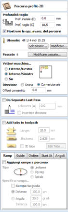
Software to use: Vectric Aspire
Launch Software
Double-click the ShopBot 3 icon to open the machine’s control program.
The
first
time
the
program
is
opened,
there
will
not
be
a
settings
file
for
the
machine.
Click
“OK”
and
a
prompt
will
appear
to
load
a
settings
file
for
the machine

Tool Movement
This
panel
provides
essential
machine
information
and
controls.
The
following
steps
will
walk
through
some
of
the
most
frequently
used
controls,
including
installing
a
bit,
zeroing
the
machine’s
three
axes,
and
cutting
a
couple
of
sample
projects.Click
on
the
yellow
button
to
bring
up
the
“KeyPad”
panel.
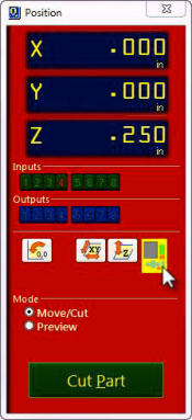
The “Easy” Control Panel
The Keypad
This window allows the user to manually move the X-, Y,- and Z- axes of the machine. Click on the blue arrows to move the spindle/router and gantry.X- and Y-axes can also be moved with the cursor buttons on the computer keyboard. Use the “Page Up” and “Page Down” buttons on the keyboard to move the Z-axis up and down.Move the spindle/router to a safe Z position below the Z proximity switch and near the middle of the deck.Click on the X in the upper right corner to close yellow KeyPad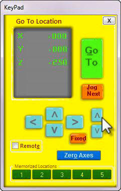
Test each axis with the keypad
Turn ON the control box. Click on the yellow keypad window icon within the red position window. If the icon is not visible, click “move/cut” under “Mode” on the red position window.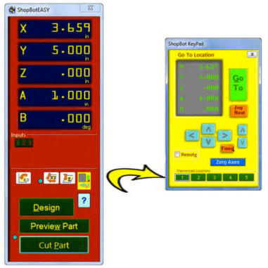
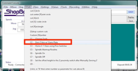
Zeroing the Z-axis
The Z-axis must be zeroed each time that the machine is turned on or bits are changed. Zeroing can be done to either the top of the material or to the table surface. Zeroing to the top of the material is a better choice when a precise cut depth is needed (when cutting an inlay pocket, for example). Zeroing to the table surface is a better choice when through-cutting parts in wood. Because wood products naturally vary in thickness, the top surface of any given area may be higher or lower than other areas. Zeroing to the table surface will provide the most consistent through-cutting results. Whichever location is chosen, the location must be identified in the CAD/CAM program (as shown here for VCarve Pro). Failure to match what is specified in the software with what is done at the table can result in ruined material and/or broken bits!Z-axis zeroing process
Ensure that the software is set to Move/Cut mode. Place the grounding clip on the bit, if possible. Otherwise, place it on the collet nut or shaft of the spindle. Set the plate down directly beneath the bit. NOTE: To test the circuit before running the zeroing routine, touch the plate to the bottom of the bit. Check that input 1 lights up on the screen and goes off as soon as contact is broken. Click on the Z zero button, or type a C2 command. The Z-axis will touch the plate twice and then move up to a safe height. The Z-axis is now calibrated and the machine is ready to cut. Place the Z zero plate back in its holster. Remove the grounding clip from the bit and secure it safely.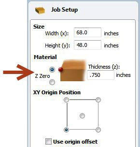

close
path cards
add cards
delete all cards
add cards automatically