Week7: Computer-Controlled Machining
Group assignment: test runout, alignment, speeds, feeds, and toolpaths for your machine
Individual assignment: make something big
Individual assignment: make something big
The model
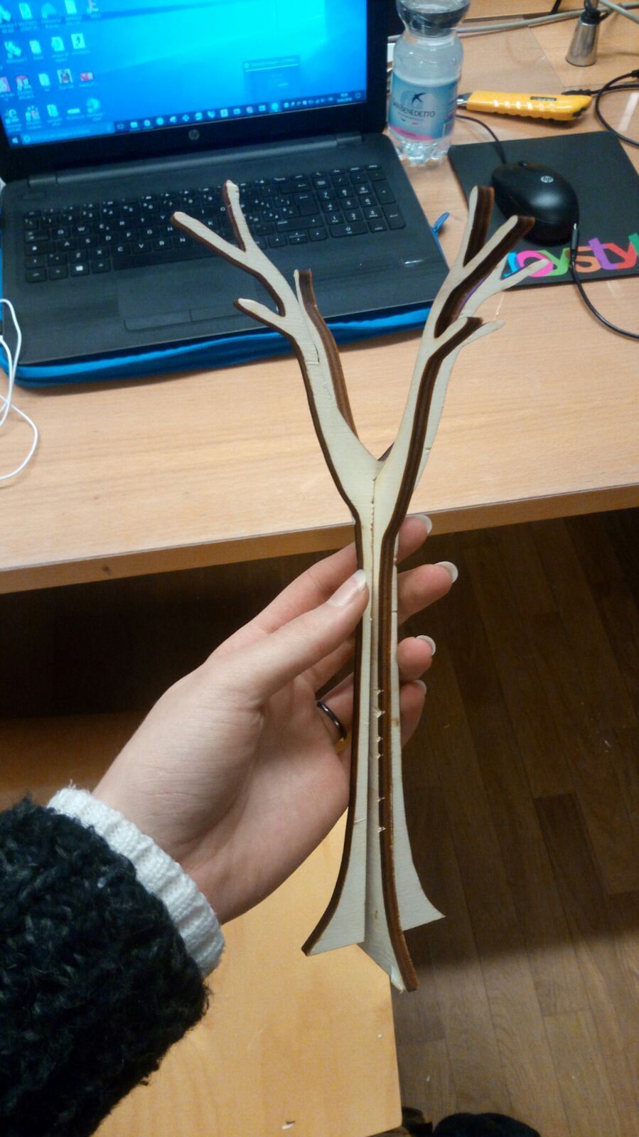
This week we had to create something more big than a chair, and and in theory we had a panel of wood 100x210cm but in practice there are not arrived in time
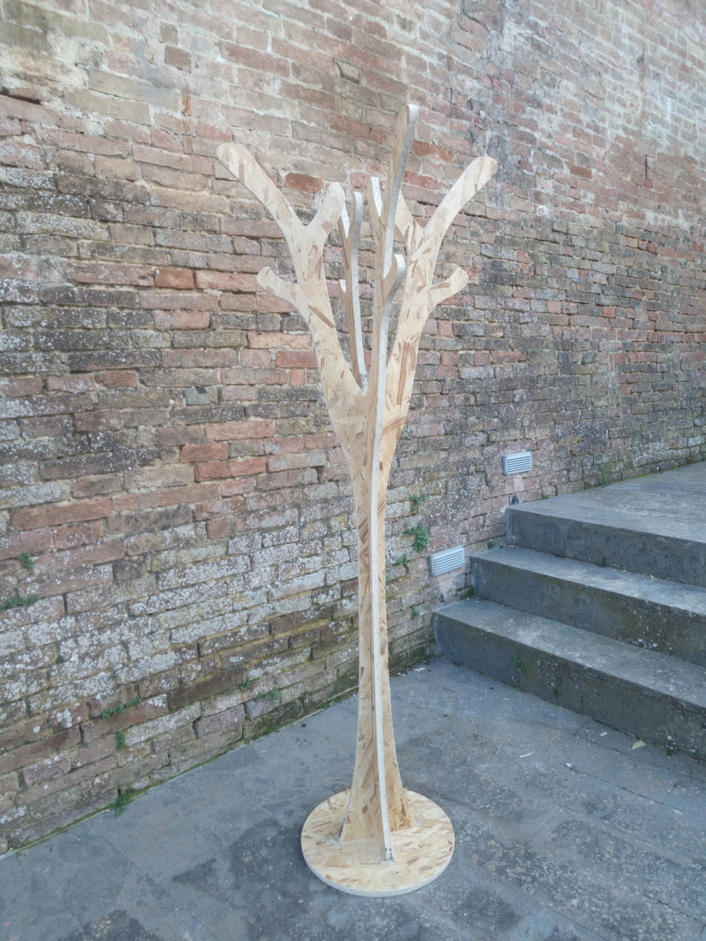
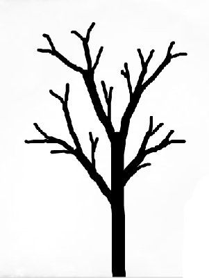
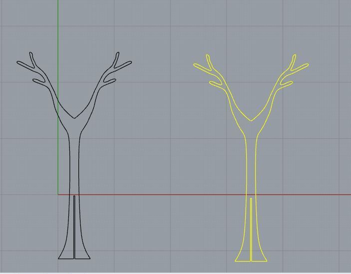
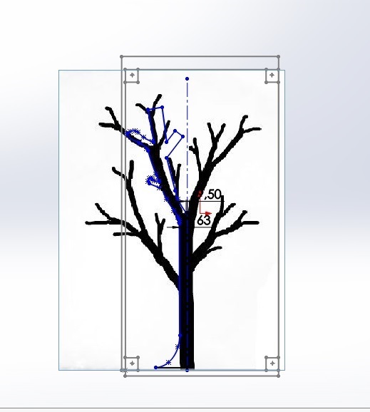
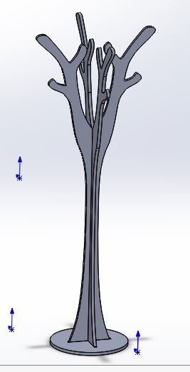
and so we did only the scale model for the moment. For the assignment I decided to create a tree-shaped coat rack, so I searched an stylized image of a tree.
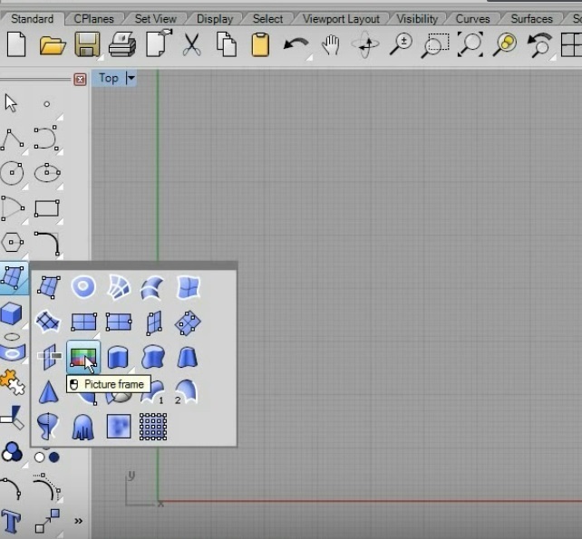
I wanted to use Rhinoceros for modeling the figure using an image guide so I searched a videotutorial and I found
this, and the new feature that I learned is basically how to insert a picture on Rhinoceros.
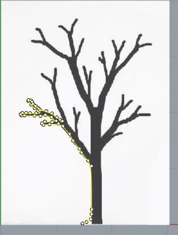
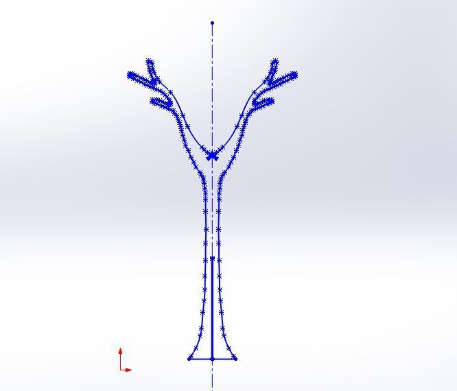
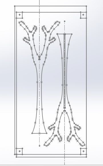
After created the track I mirrored it and adjusted the figure.
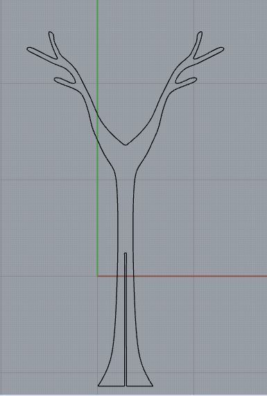
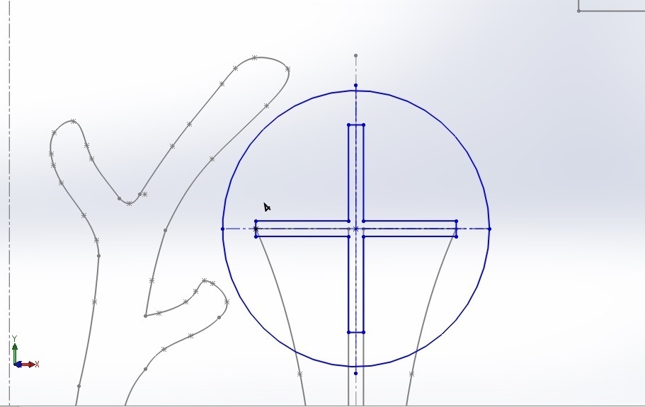
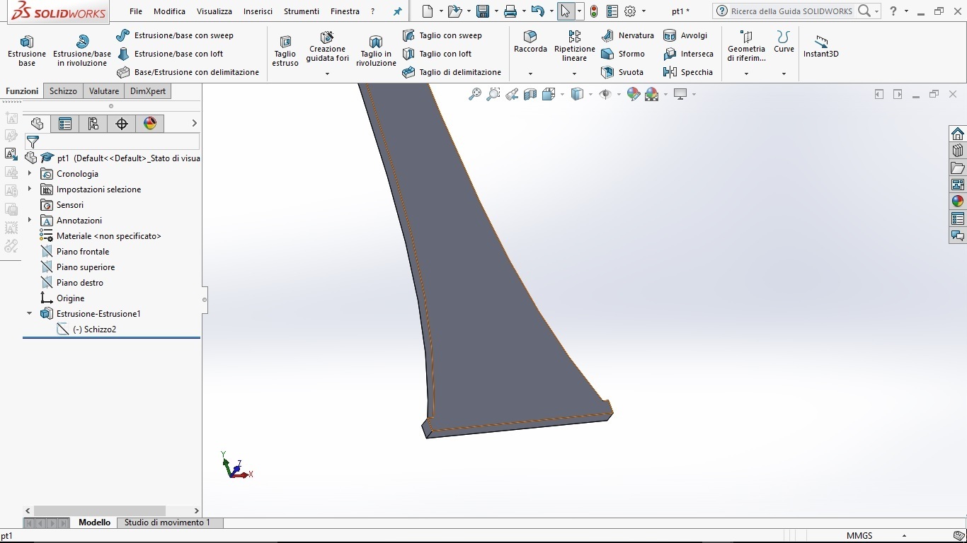
I created the joints...
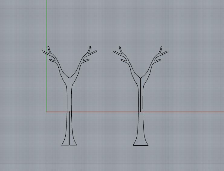
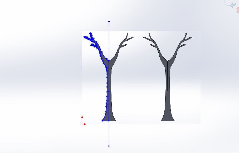
After the extrusion I was having trouble changing the size of the joints, so since I had already done it with Solidworks I decided to export the images
from Rhinoceros and recreate them again with Solidworks.
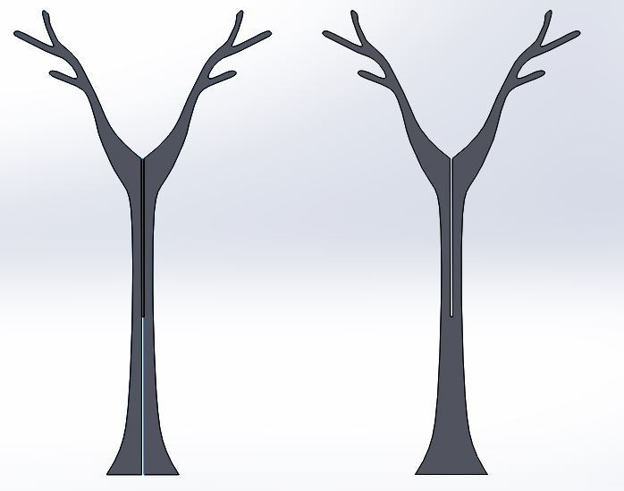
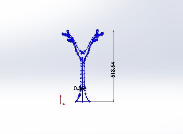
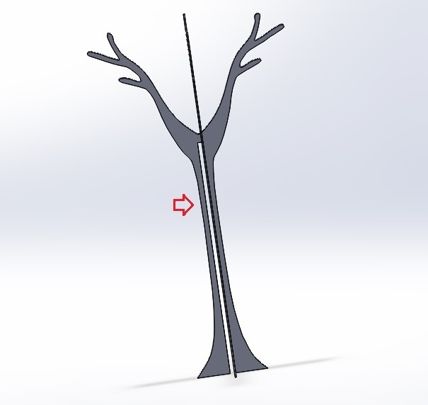
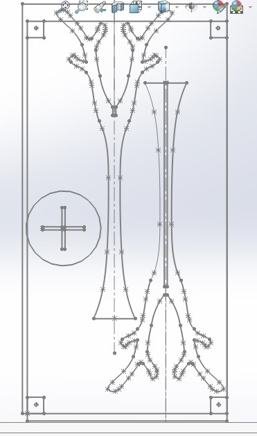
I changed the type of joint because I thought that there could be problems with the top of the coat rack
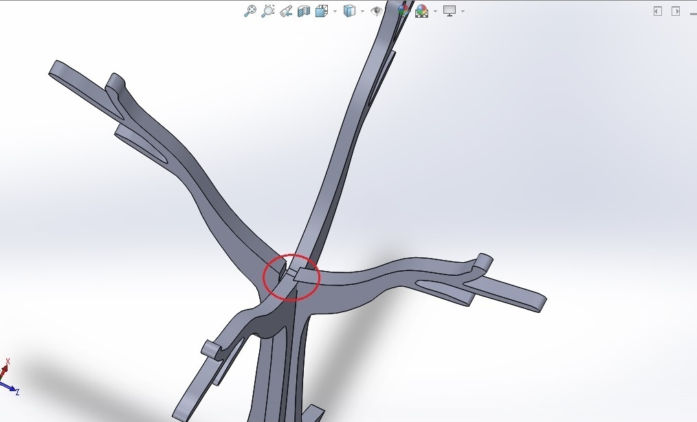
After the Assembly I realized he did not put the same thickness in extrusion, so I changed it, but in the assembly the joint was wrong.
The issue has been resolved remake the assembly process.
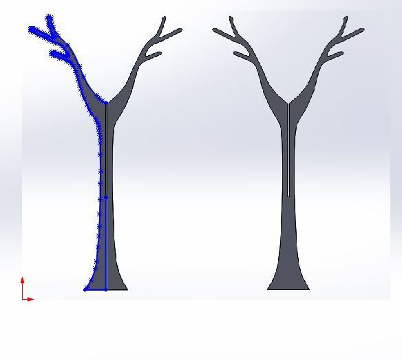
Then I exported the figure to open it on illustrator but after several attempts I saved the file badly I knew I had to do this steps
-->save as
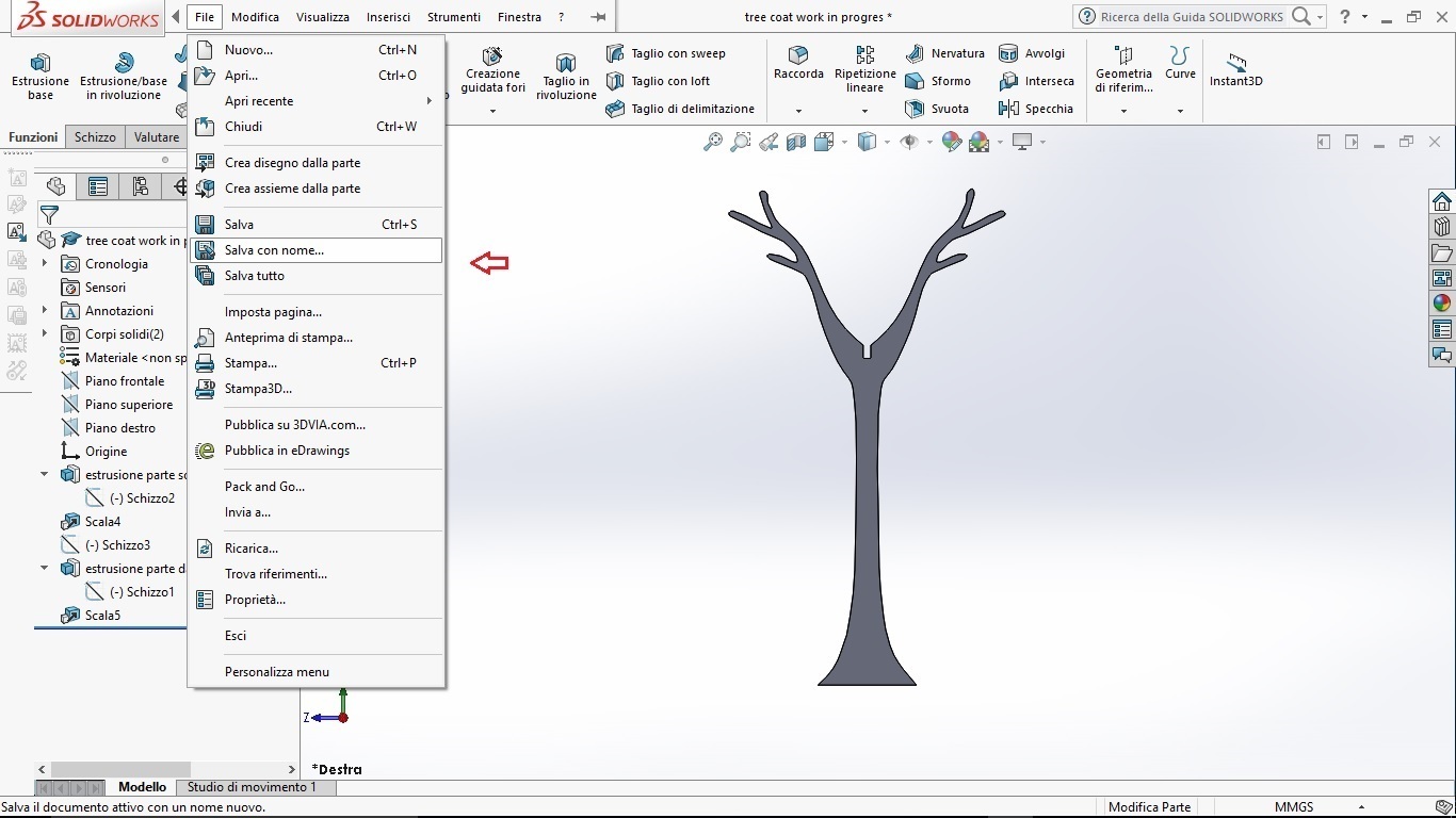
-->Dfx
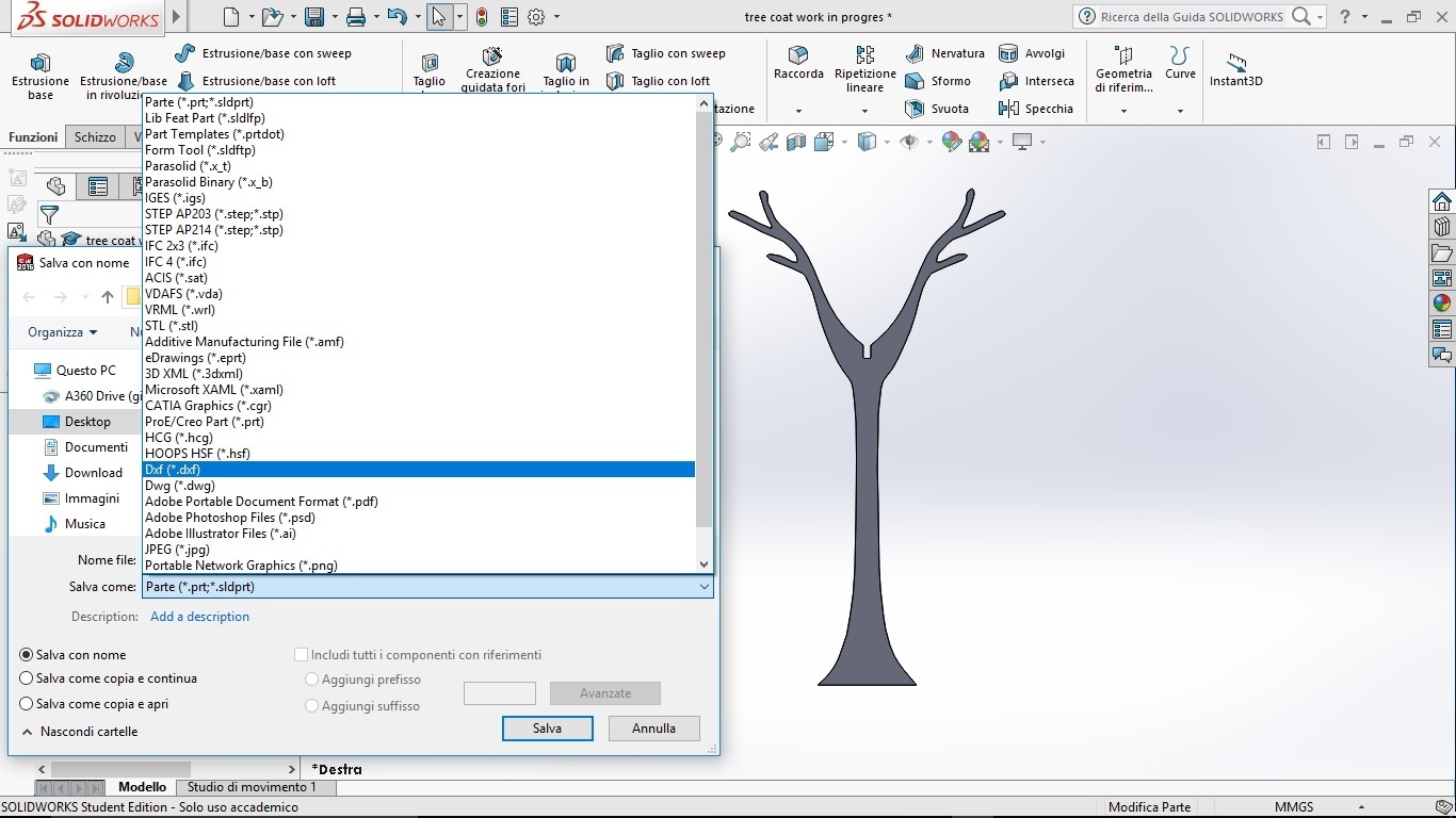
-->faces and select the surface
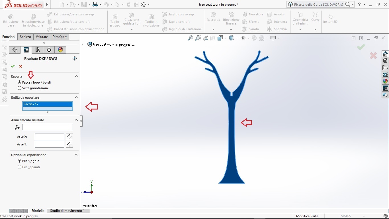
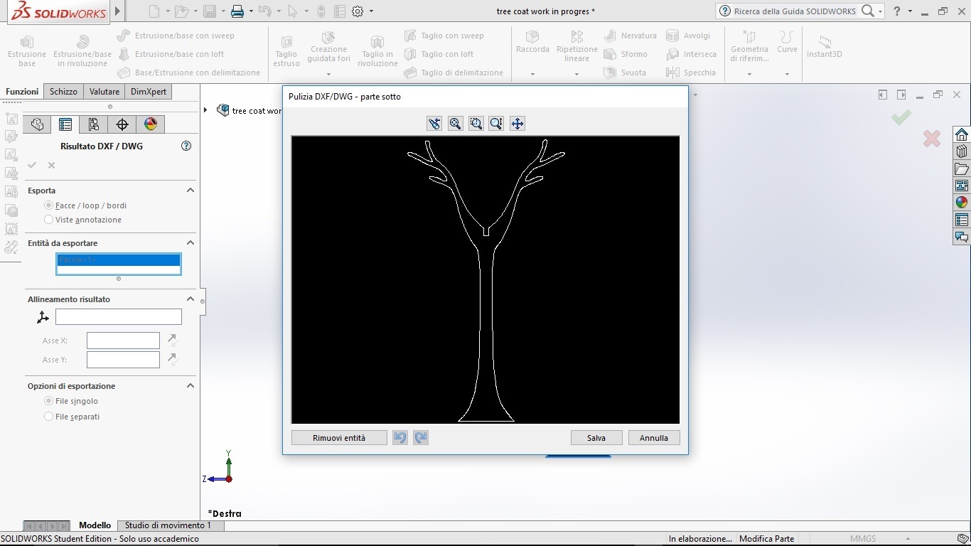
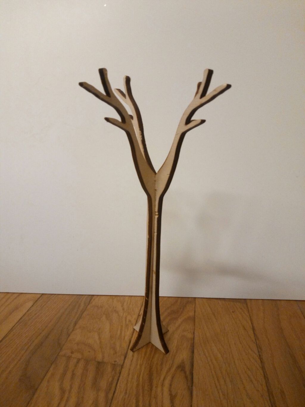
And this is the result. Then I did the same process for the other part
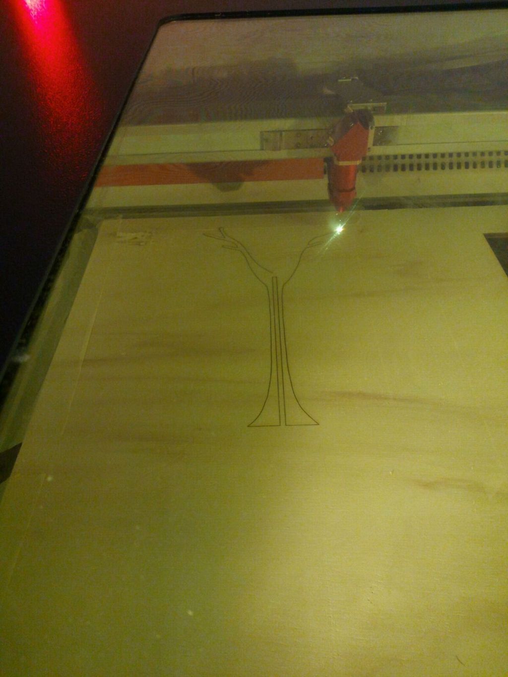
Then I opened the 2 files on illustrator and I cut it with the laser cut to create the model
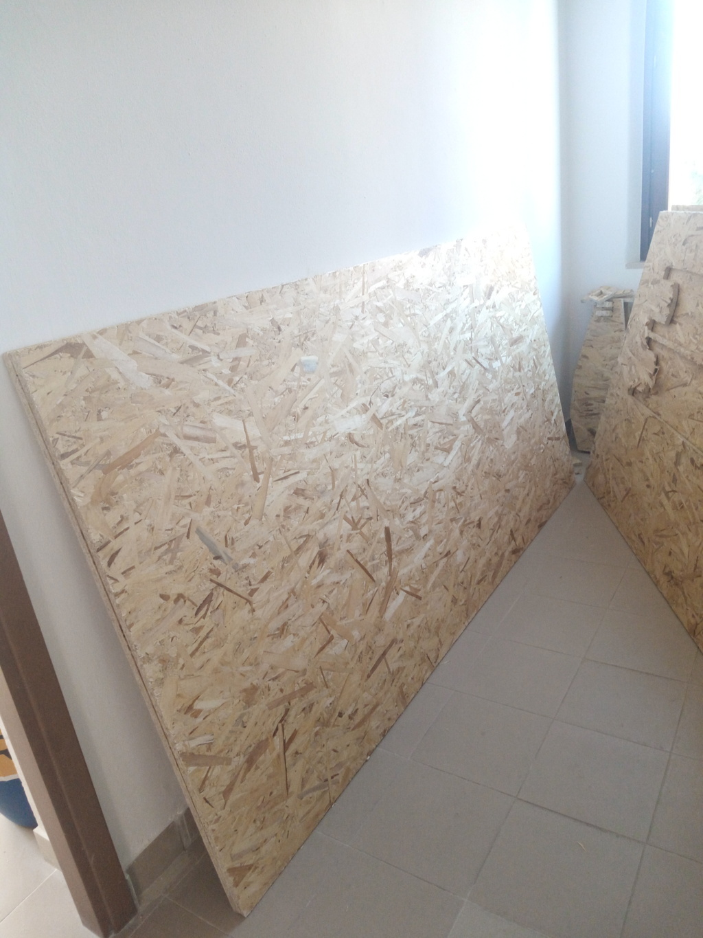
Update 07/04/2018
Finally the wood panels arrived and so I could finish the week assignment during the 11th week.
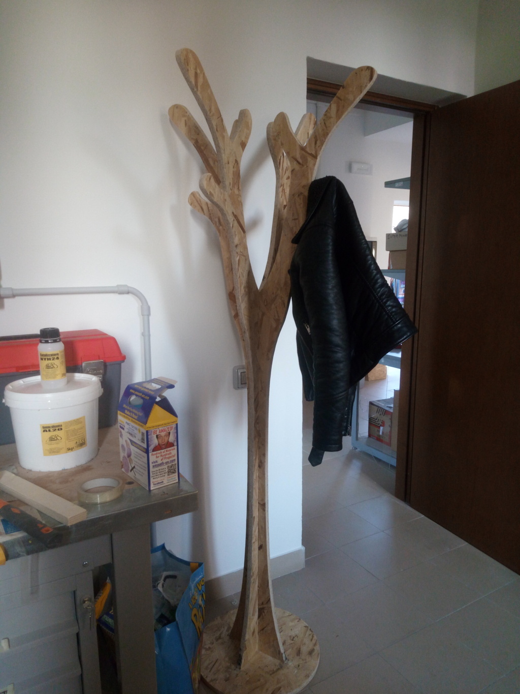
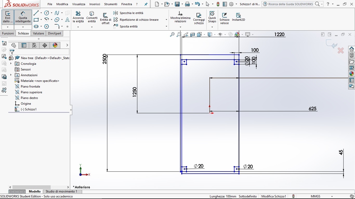
After making the scale model I decided to make some changes, including creating a base to make the hanger more stable.
This time I used Solidworks, since in the 10th week I created the sword and I learned to use better this program.
They also explained to us the importance of creating a model that it doesn't give problems during the milling,
that there is enough space for the screws that hold the panel screwed to the base so that the tip does not pass over it.
So I took the measurements of both the panel and the base of the shopbot to create a contour within which to remake the model.
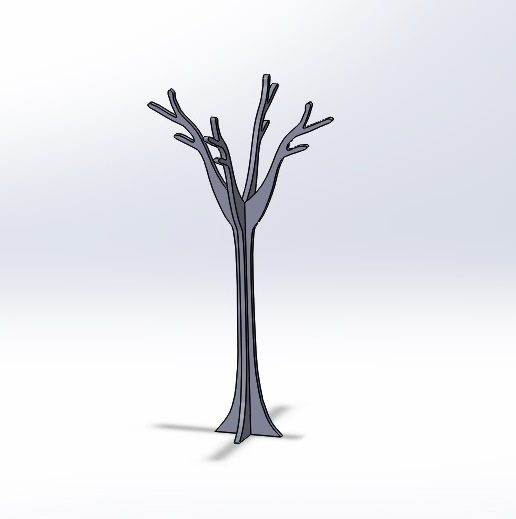
To verify that the joints were correct I made the assembly of the parts and I realized that the base of the tree could be made better,
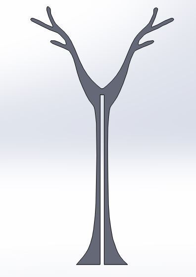
so I modified it...
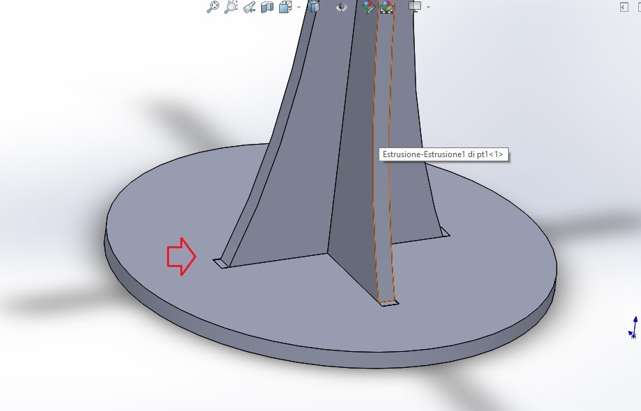
...and the end result is this
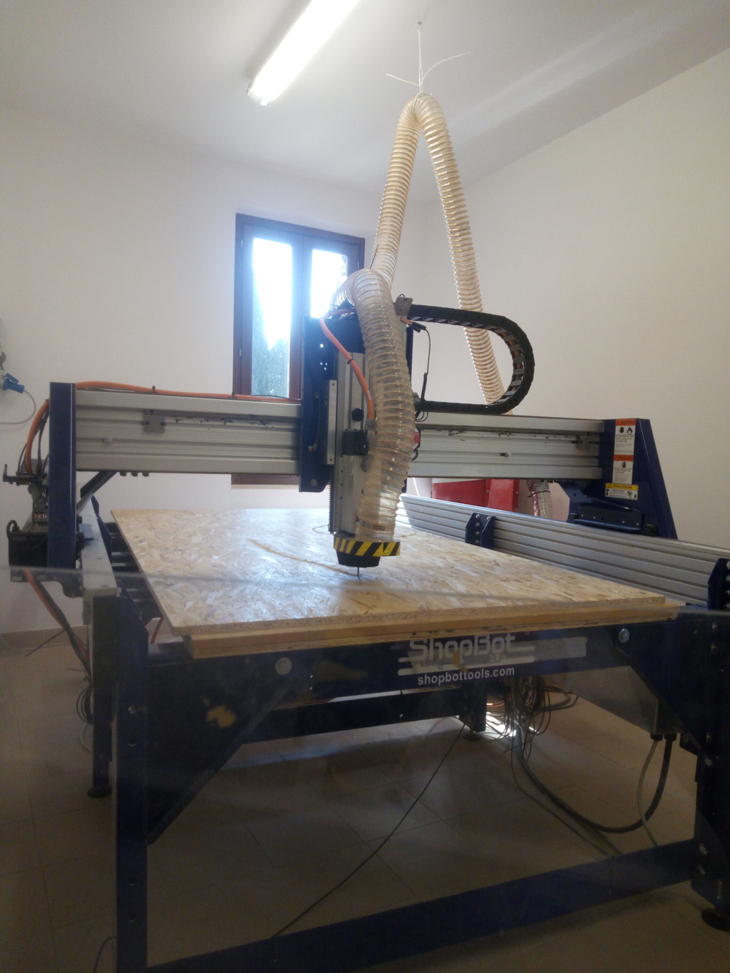
VCarve Pro-ShopBot edition
After exporting the Dxf file I opened it on the Vcarve pro-ShopBot edition program to prepare the file for the ShopBot. Having never used it
I asked Simone Guercio for help, who very patiently accompanied me in the creation of the file. Below all the phases.
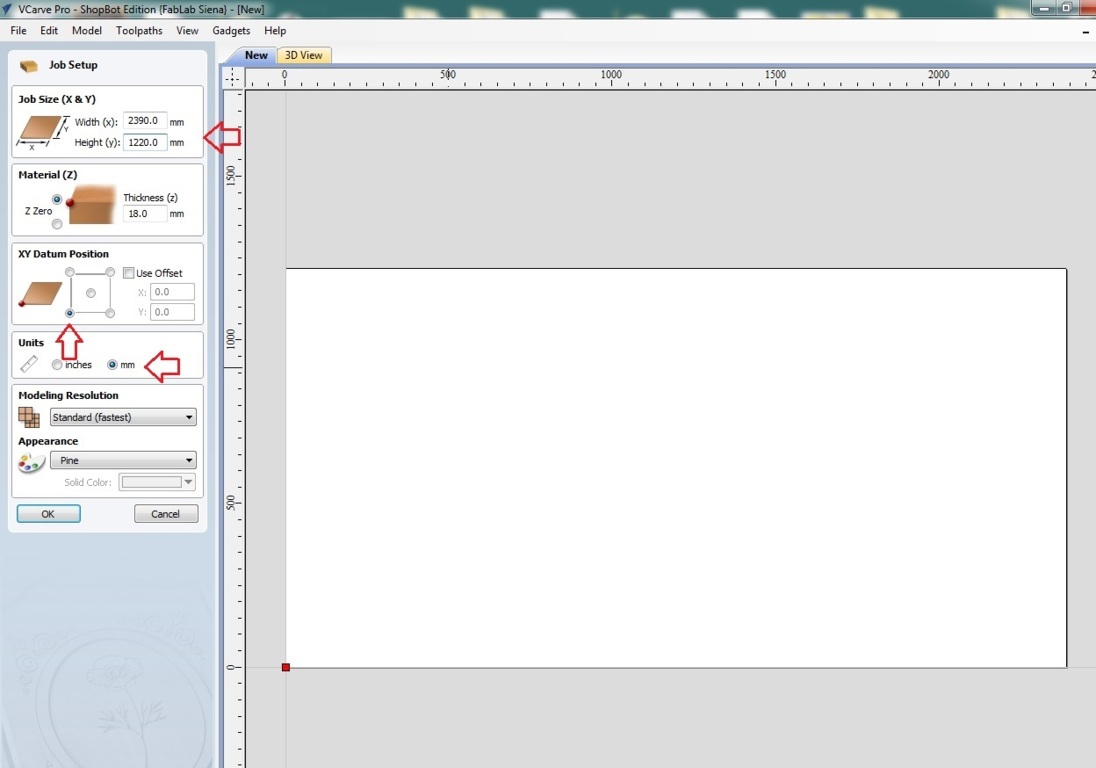
The first step was to set the size of the work table
The first step was to set the size of the work table
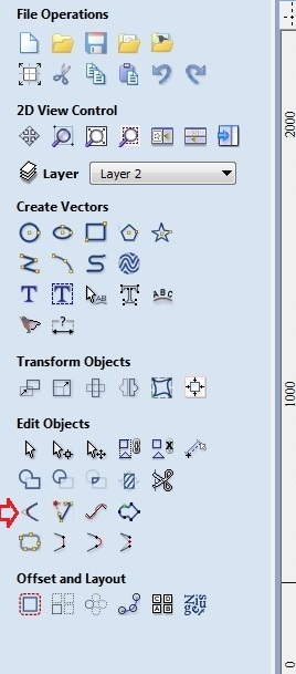
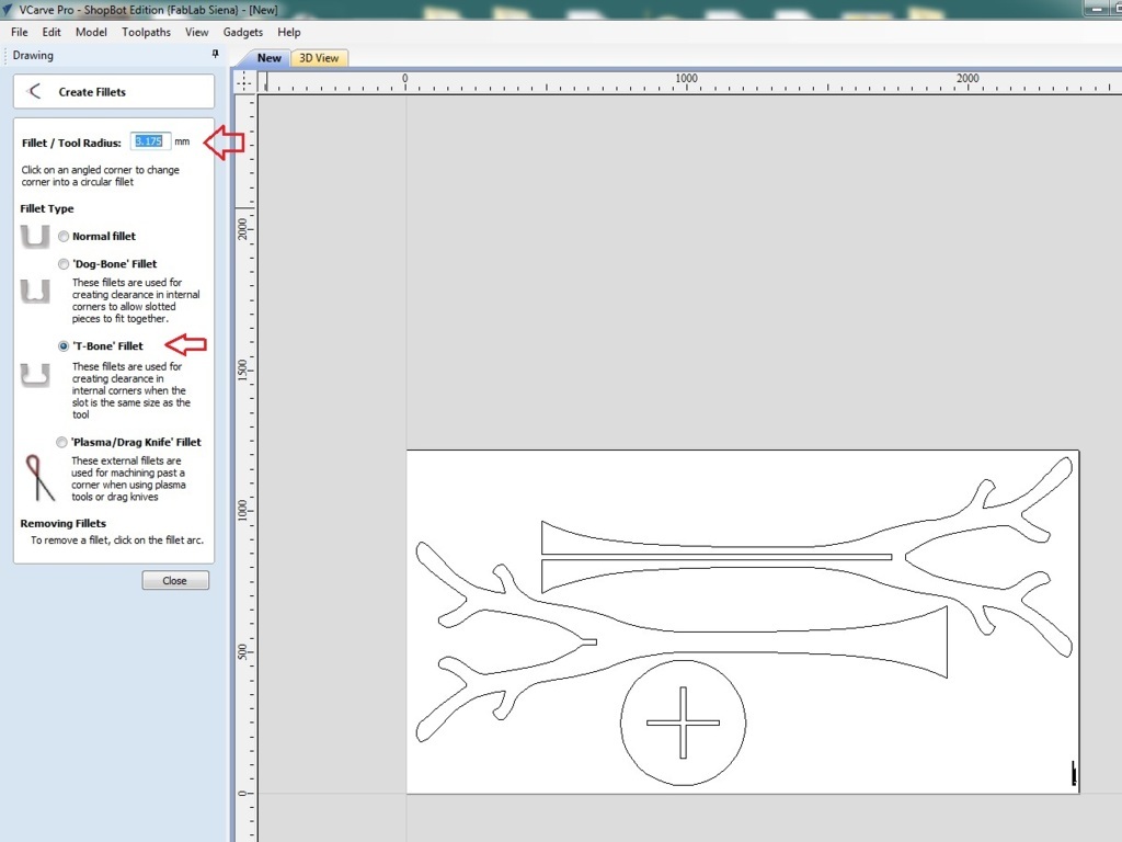
Then I inserted the t-bone with the appropriate tool
Remember: the radius tool must be half the tip diameter
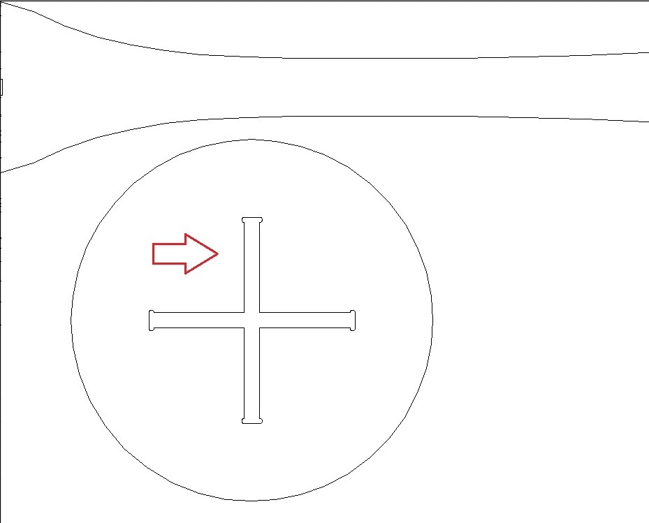
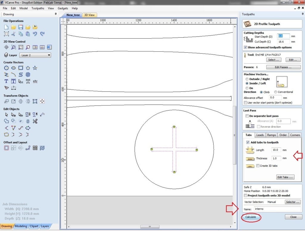
When you do these kinds of jobs you always start by milling the internal parts, in my case the cross of the base. The steps are these:
select what you want to mill
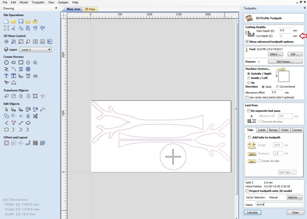
Open "toolpaths" (located at the top right) and select "2D profile toolpath", at this point you can change the parameters for cutting,
such as the tip, how many passes do, the depth of cut (which in this case is bigger than 0,6 mm to be sure that the wood will be cut well)
and the type of cut (external or internal).
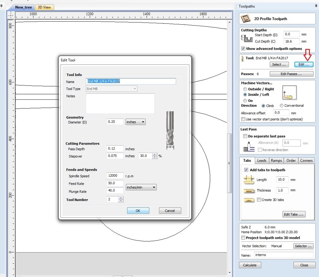
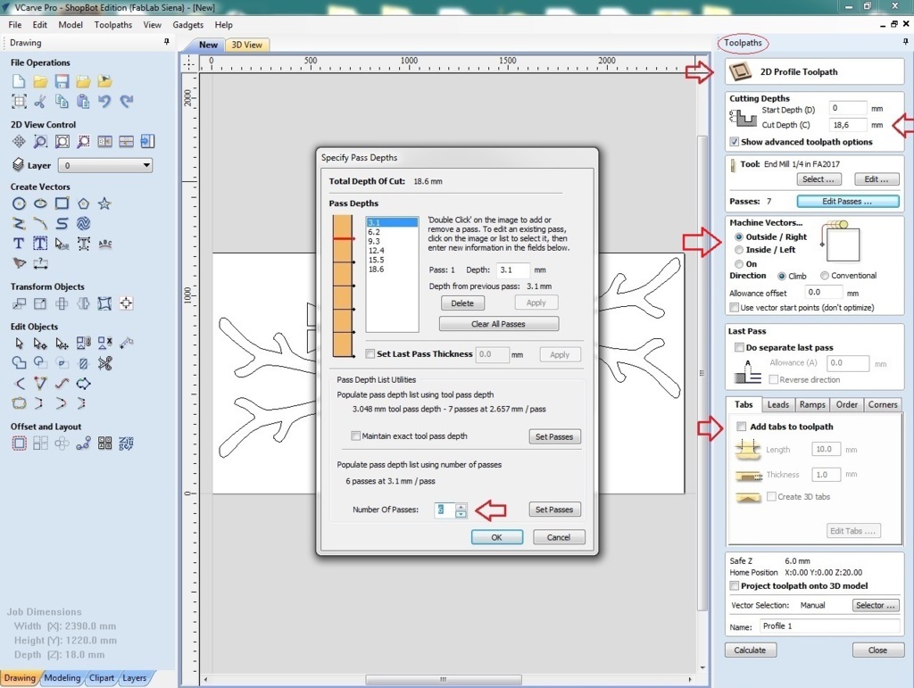
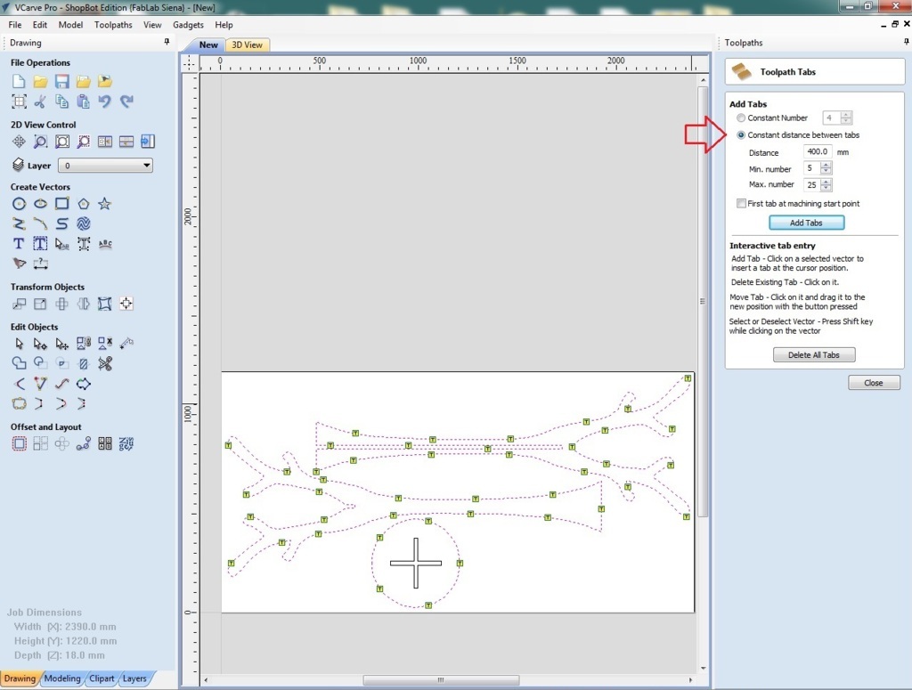
To avoid that the pieces can jump away from the table you can add the tabs, selecting "add tabs" and "edit tabs".
This operation can be done automatically or manually
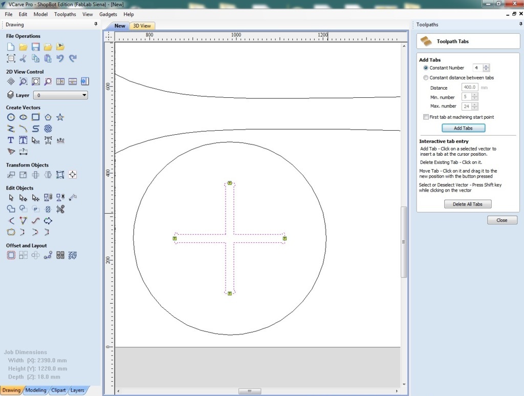
I created small tabs to be able to detach the pieces later, at this point I changed the name of the file and I pressed on "calculate"
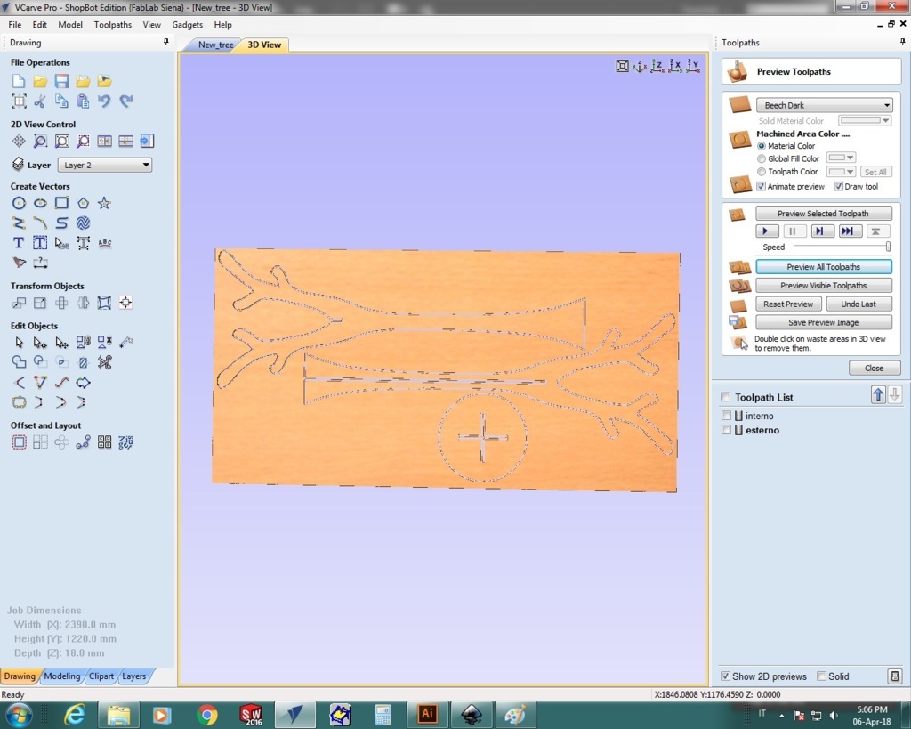
Now we can see the preview of the cut through the "preview all toolpaths" option.
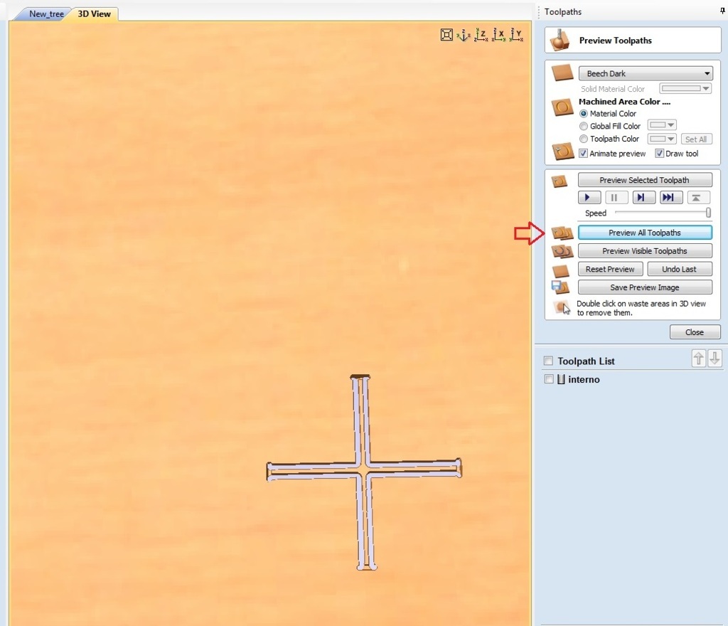
At this point we can save the file by selecting it one at a time from the toolpath list
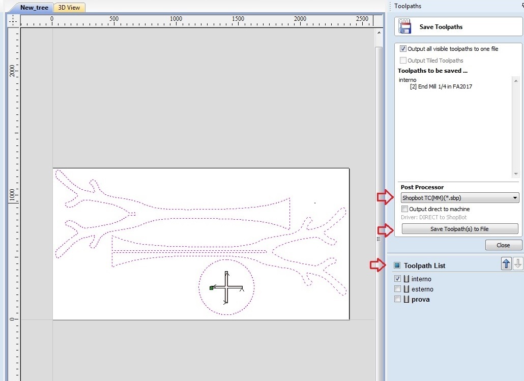
Now exit from the 3D view and go back to the drawing, where once you have selected the figure for the external cutting, you have
to do the whole procedure again.
to be 100% sure that the tip will not pass over the screws during the cutting, it is advisable to make a test cut with the tip z lift up a
few cm and see the path that makes. To do this it's necessary to put the cut depth at a low number, for example 1mm
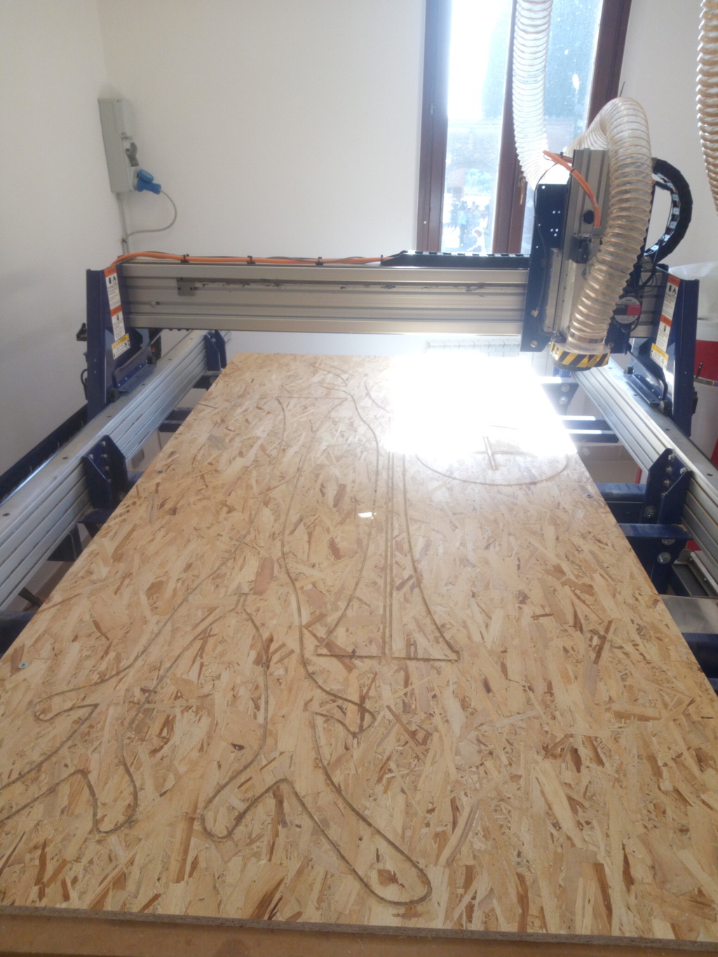
Milling and assembly