Week 3: Computer-controlling cutting
Individual assignment:cut something on the vinylcutter design, lasercut, and document a parametric press-fit construction
kit, accounting for the lasercutter kerf, which can be assembled in multiple ways
Group assignment: characterize your lasercutter, making test part(s)that vary cutting settings and dimensions -> link here
Group assignment: characterize your lasercutter, making test part(s)that vary cutting settings and dimensions -> link here
The vinylcutter
Let's start with the realization of the sticker: to create mine I used Inkscape.
For the realization I followed the instructions of Flavio Lampus.
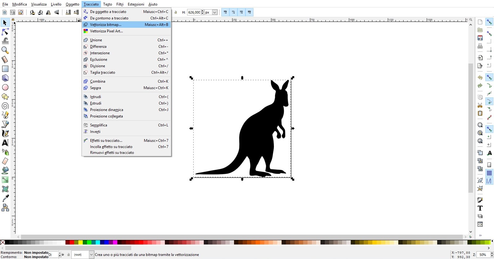
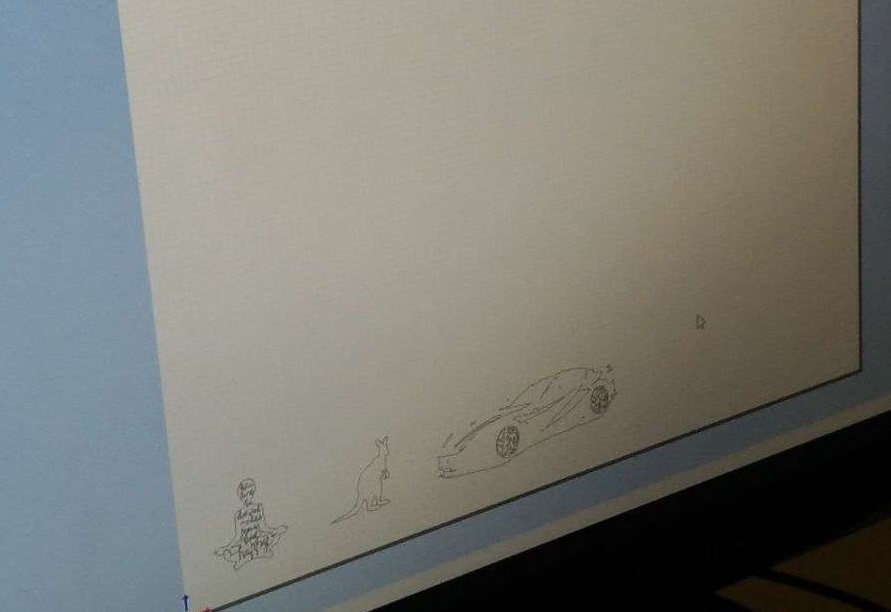
First of all I had to choose and SVG image and I opted for a simple figure, the silhouette of a kangaroo.
I opened the file on Inkscape, then I selected Trace ->vectorize bitmap. With this operation the image will maintain the same quality.
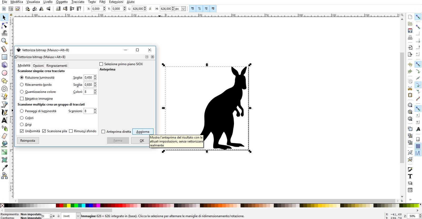
In this window you can modify various parameters to your liking, in my case the image is so simple that I didn't make any change
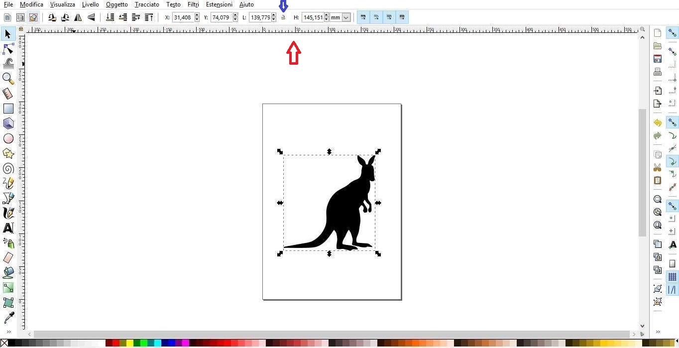
Then I changed the measures (red arrow). If you want the same proportion between the two measures, just select the lock (blue arrow)
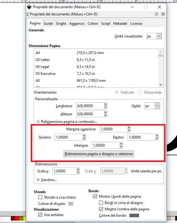
Then I opened document properties to change the page size (see red rectangle) and I saved the document in the png format

I opened the file on Inkscape, then I selected Trace ->vectorize bitmap. With this operation the image will maintain the same quality.
In this window you can modify various parameters to your liking, in my case the image is so simple that I didn't make any change
Then I changed the measures (red arrow). If you want the same proportion between the two measures, just select the lock (blue arrow)
Then I opened document properties to change the page size (see red rectangle) and I saved the document in the png format
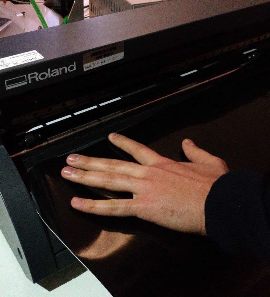
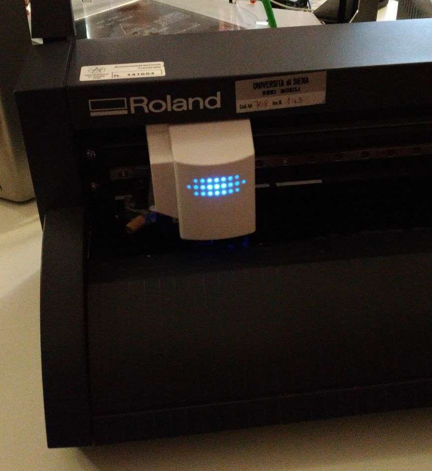
Saving this image on a USB drive, I trasfered it to the PC connected with the Vinylcutter (a Roland CAMM-1 GS-24)
and I opened it with the software CutStudio using the command Import.
Since this passage was made with my mates I didn't report my documentation of the process.
To see how we did you can go to the documentation of Eleonora Piccinelli.
Before making the cut we prepared the vinyl sheet in the Roland plotter. At this point we set the blade origin with the enter button.
Before making the cut we prepared the vinyl sheet in the Roland plotter. At this point we set the blade origin with the enter button.
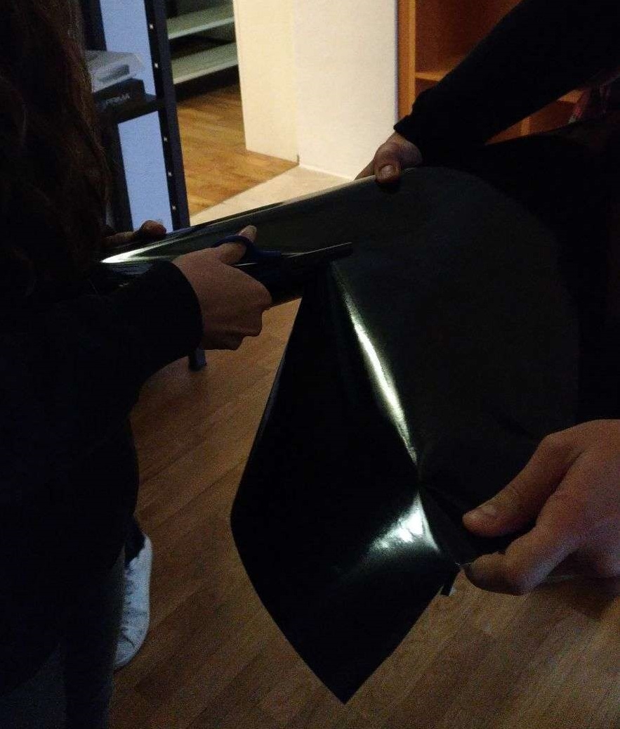
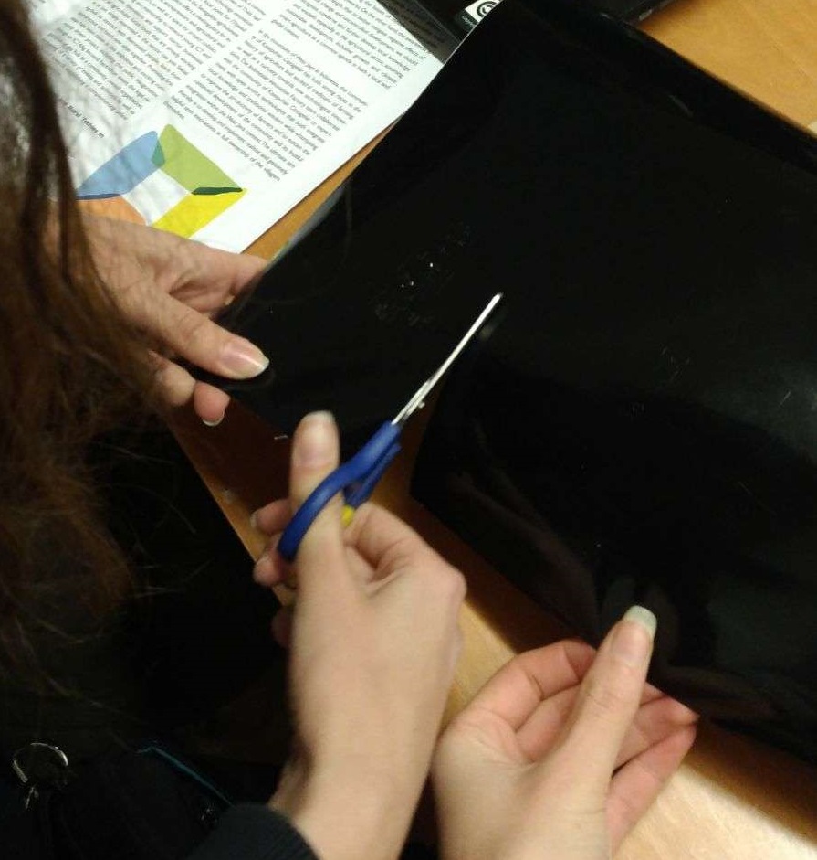
I removed the excess vinyl from the sticker and put the transfer film on it.
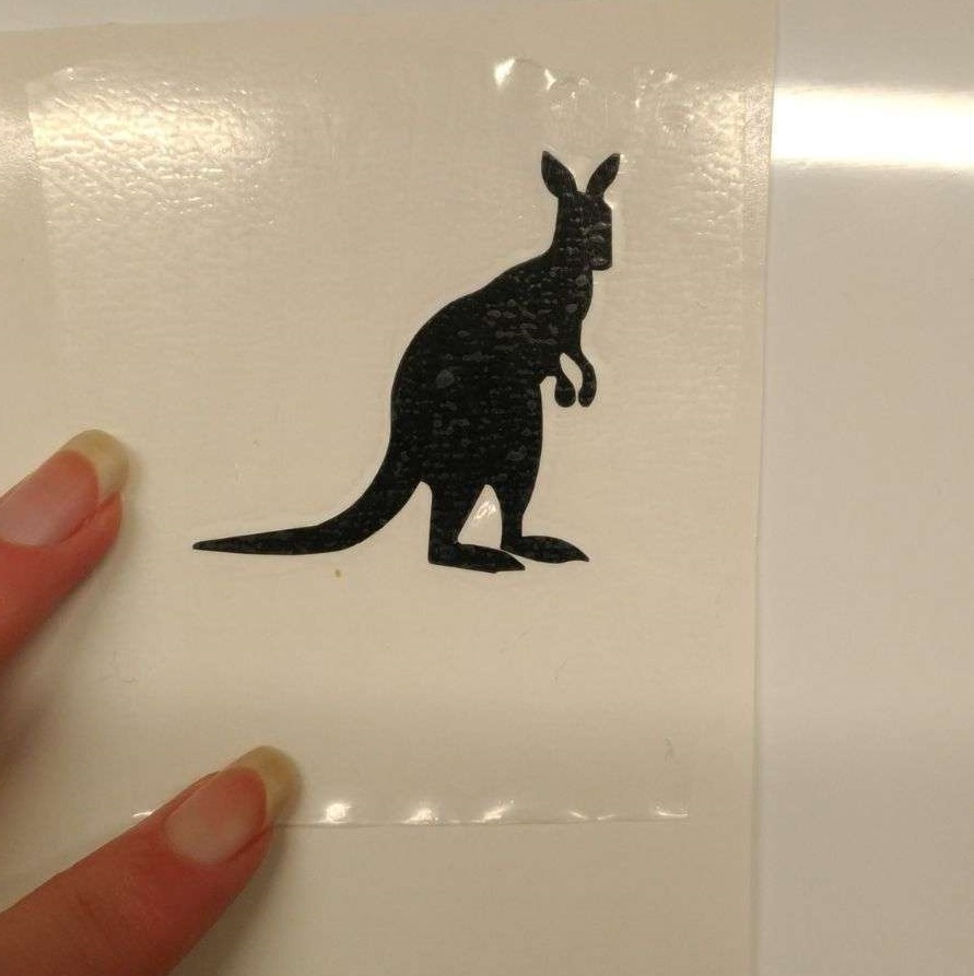
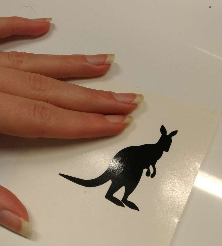
The kangaroo-sticker is ready!
A parametric press-fit construction kit
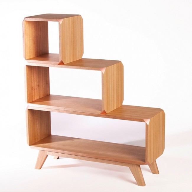
Since as much as I try I can not find an original idea for this assignment, I decided to make a desk cabinet with modular shelves
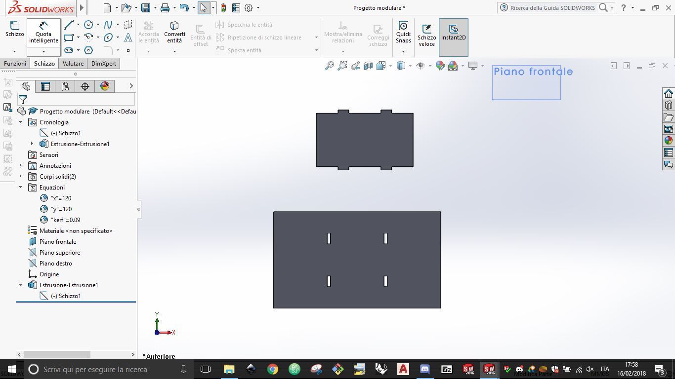
I wanted to try solidworks to create a modular and parametric project.
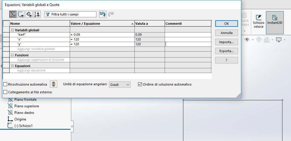
Since I was working in the laboratory with Eleonora she explained to me how to enter the equation parameters on solidworks (but obviously I must have misunderstood because the parameters I put here are not parametric). Before modeling, I went on tools --> equations and I added the values in the box below. I gave a quote to an X and an Y and I added the kerf value after the test I made with my group (but as you will see later I have done many tests of kerf by myself).
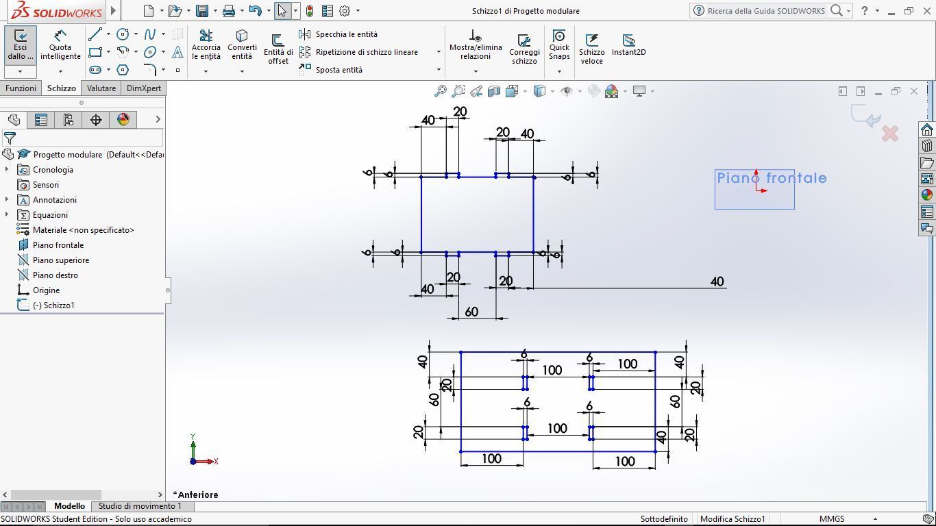
After entering the parameters I started to model the parts of my small cabinet with shelves.
Before creating the joints you have to keep in mind how to insert the kerf in the equations:
male = d + 2*kerf
female = d - 2*kerf
(But I have not even entered the wrong equations in the measurements).
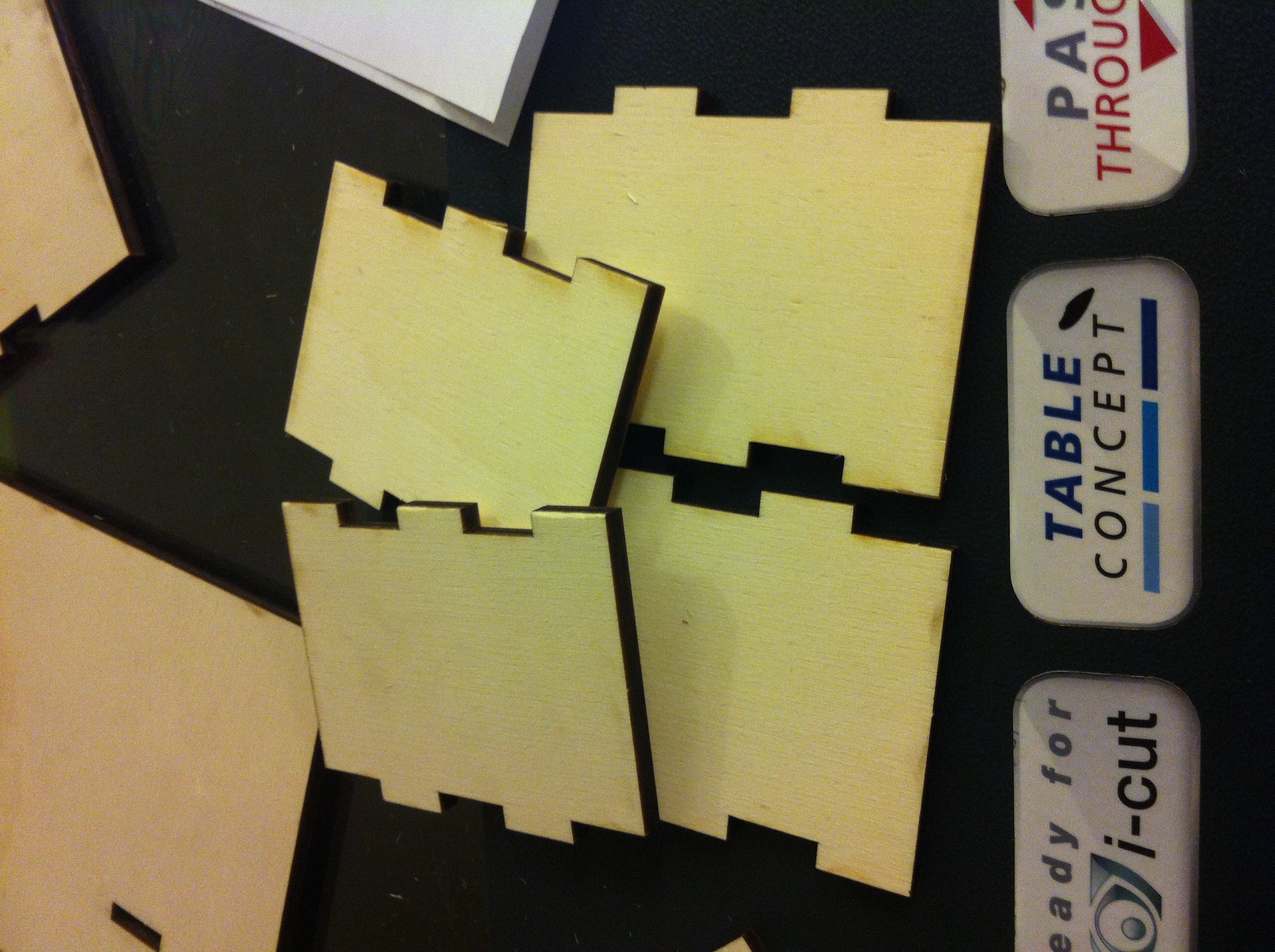
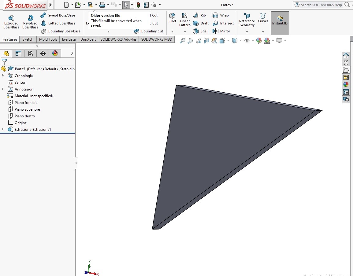
In my first project I thought to realize only two components of the cabinet wich could be used to make different compositions with the shelves, but as you will see later the realization was not successful
That was my first extrusion on Solidworks
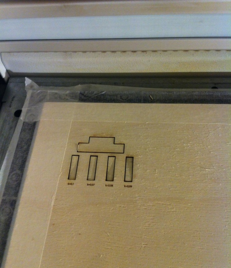
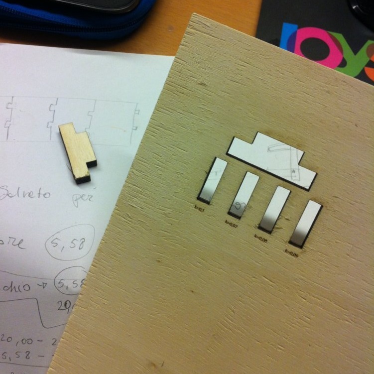
As I mentioned before, I did various tests of kerf on my plywood board because apparently the kerf varies depending on various parameters (thickness, humidity, not flat table) so I modeled a little interlocking to find the right parameter.
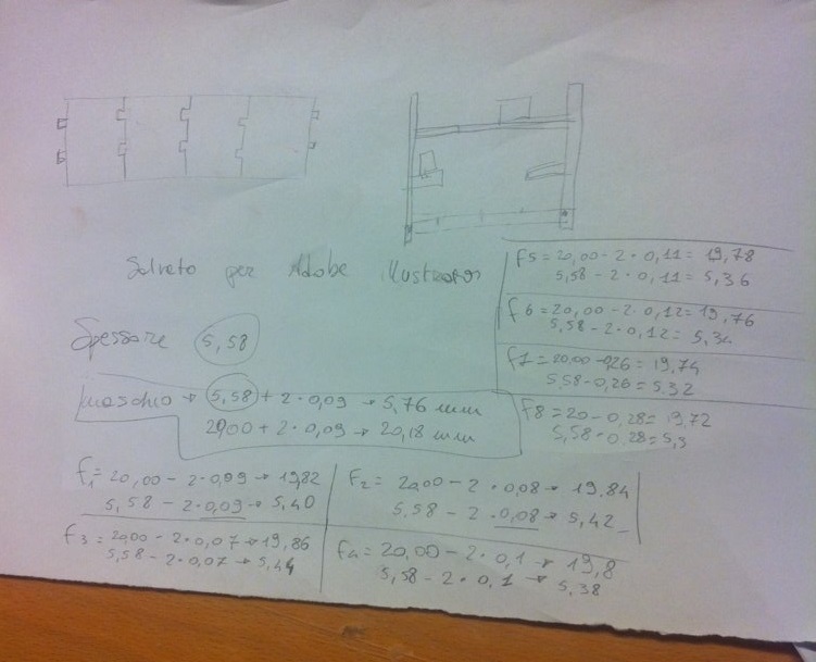
I did a lot of calculations to understand well what the kerf variable involved in the construction of the joints. In fact this kerf is nothing but a gap that the laser cutter creates and that must be compensated by doing the right calculations, then it must be added to the male joint (which is smaller) and must be removed to the female (which is bigger).
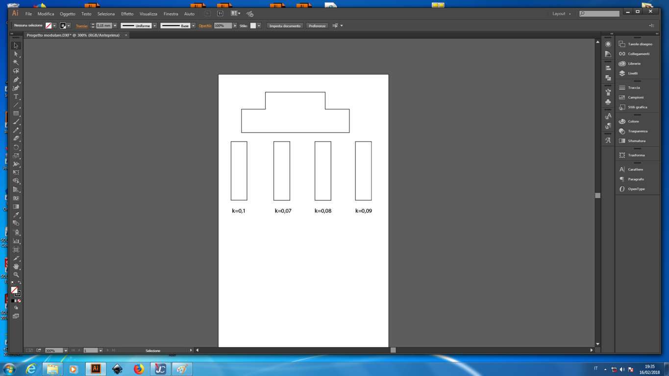
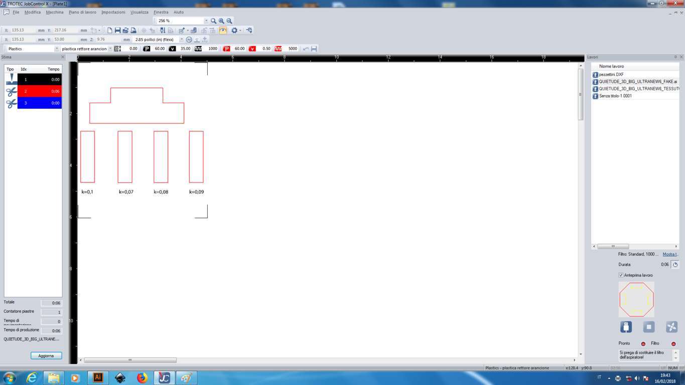
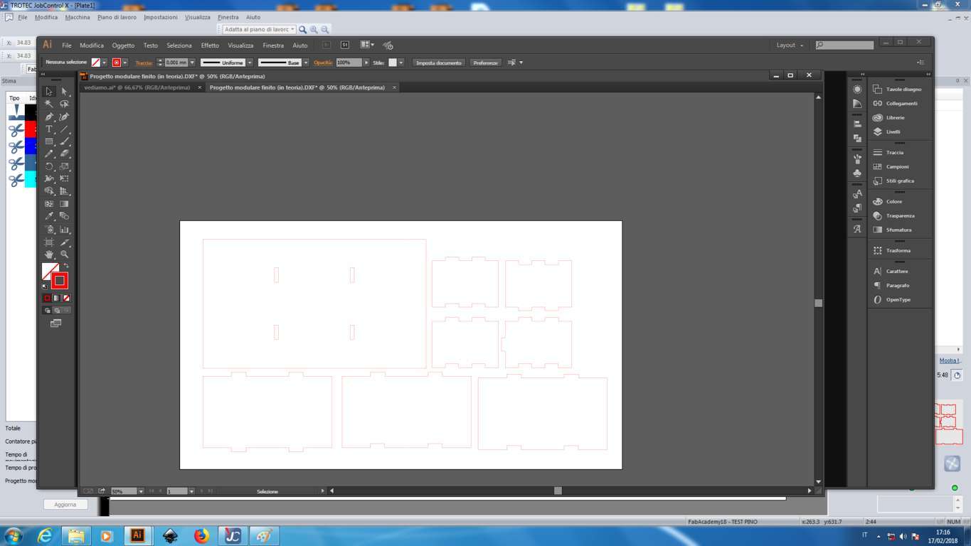
After creating the joint I opened it on Adobe Illustrator, I made the trace thick 0.001 mm and I made it red (255 RGB color). Then I sent the file to the program of our laser cutter (JobControlX) using the cutting parameters found with the group.
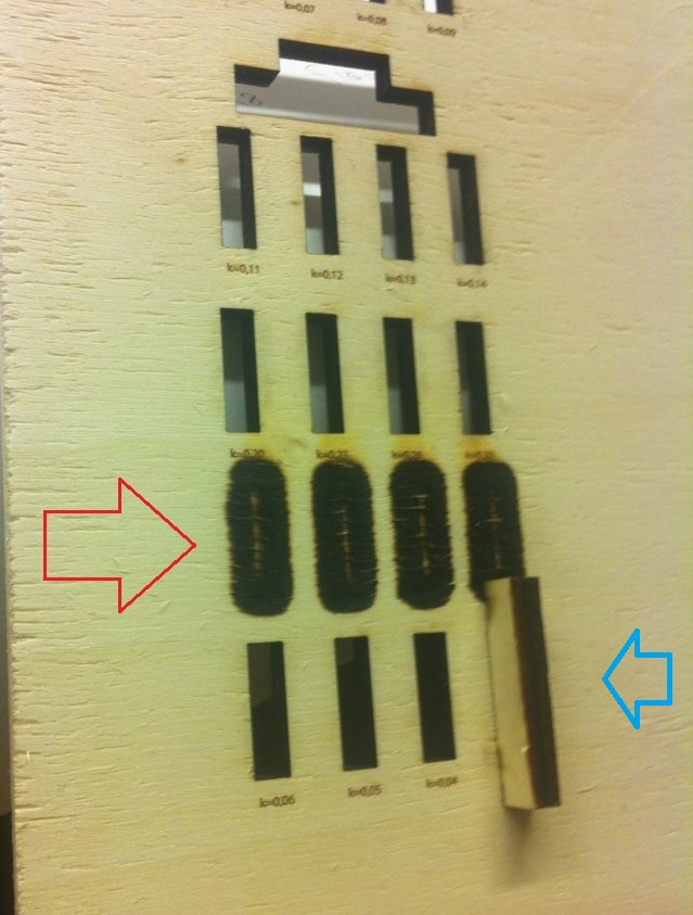
Apparently the first calculations weren't satisfactory because the joint didn't work, so I did other tests until it joints.
finally I found my kerf and the right cutting parameters
speed 0,5
power 85%
kerf 0,03
so I changed the parameter of kerf and cut all the parts of my project
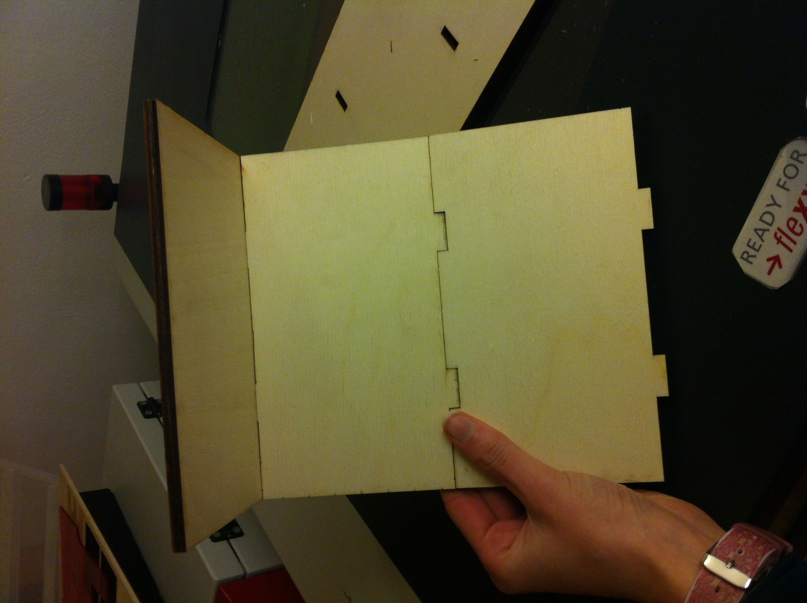
But as I said before, having made a mistake to create the equations on Solidworks, the work failed, in fact I had to force in some places to fit the pieces while the shelves didn't fit together because the joints were too large.
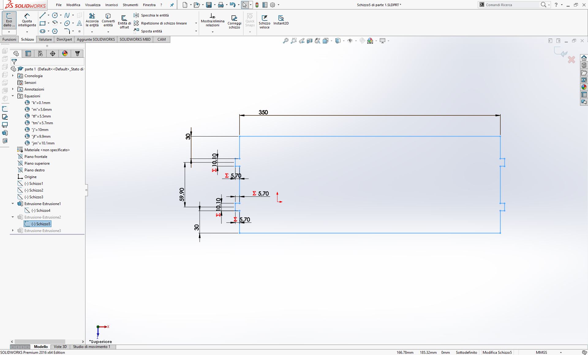
I designed and built the pieces of my modular project again, this time I did some research to better understand how to insert and use the equations on Solidworks. So I looked at Silvia Palazzi documentation and this page on Solidworks help. So I did the equations and those are the values:
"k"= 0.1mm'kerf
"m"= 5.6mm'material thickness
"tf"= "m" - "k"'female thickness
"tm"= "m" + "k"'male thickness
"j"= 10mm'joint
"jf"= "j" - "k"'female joint
"jm"= "j" + "k"'male joint.
And as you can see I added the equations to measure the different parts of the sketch
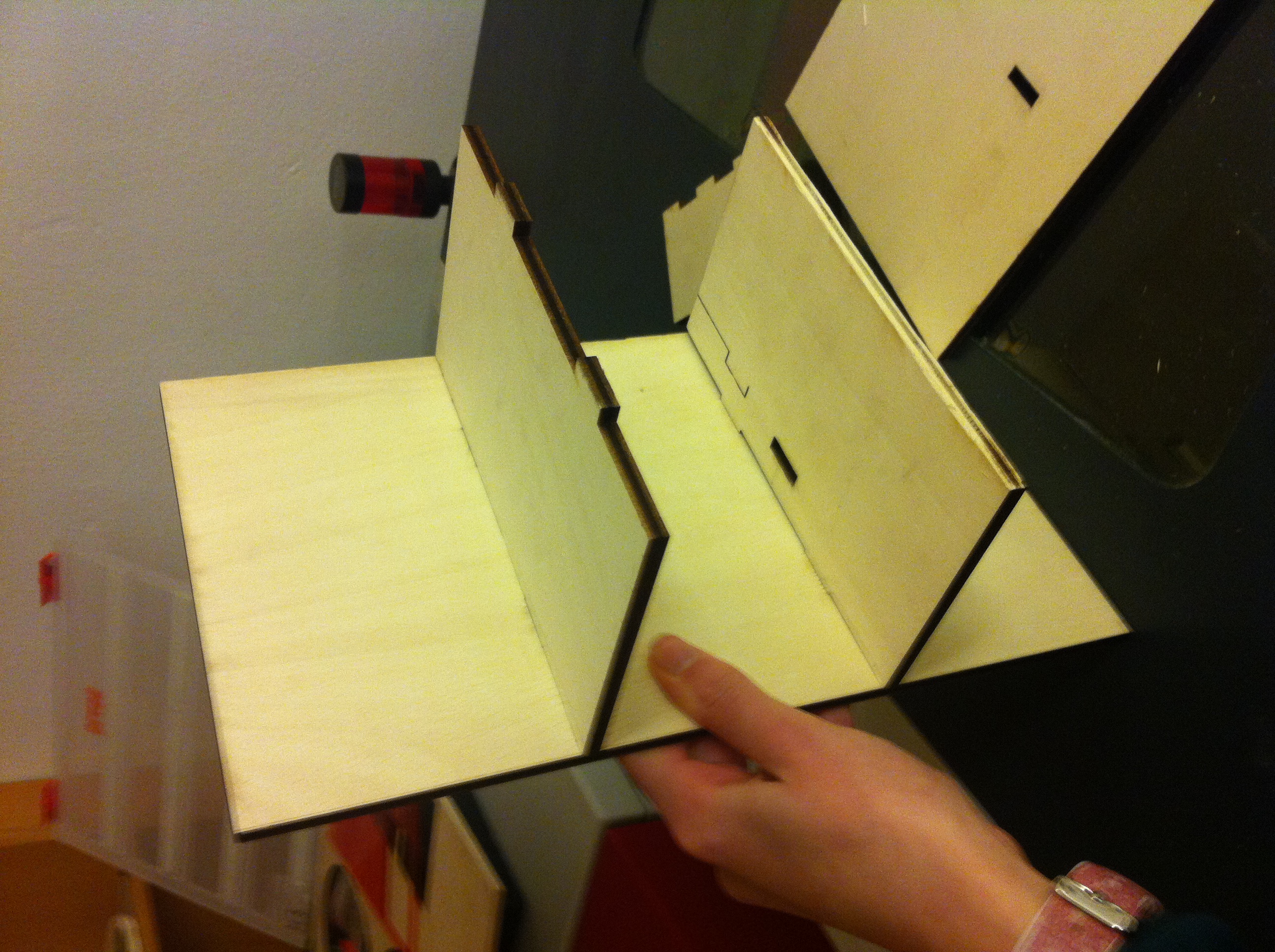
I also did the assembly to see the final result and make sure that everything would get fit.
When I assembled everything together I noticed that the shelves were not straight, so I made a support and I glued it underneath, in this way the result is improved.
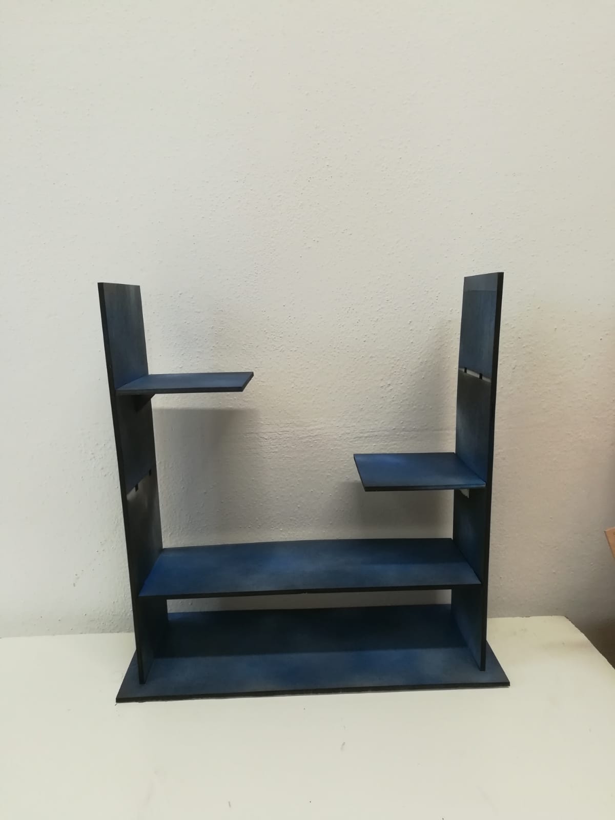
And this is the final result. To give it a different look I used the blue spray paint. The purpose of a parametric kit is to maintain the same proportions thanks to the equations. In this way I can make this object in any size I want without changing each measure one by one. The modularity of this object consists in choosing the disposal of the shelves according to your needs.
I wanted to try solidworks to create a modular and parametric project.
Since I was working in the laboratory with Eleonora she explained to me how to enter the equation parameters on solidworks (but obviously I must have misunderstood because the parameters I put here are not parametric). Before modeling, I went on tools --> equations and I added the values in the box below. I gave a quote to an X and an Y and I added the kerf value after the test I made with my group (but as you will see later I have done many tests of kerf by myself).
After entering the parameters I started to model the parts of my small cabinet with shelves.
Before creating the joints you have to keep in mind how to insert the kerf in the equations:
male = d + 2*kerf
female = d - 2*kerf
(But I have not even entered the wrong equations in the measurements).
In my first project I thought to realize only two components of the cabinet wich could be used to make different compositions with the shelves, but as you will see later the realization was not successful
That was my first extrusion on Solidworks
As I mentioned before, I did various tests of kerf on my plywood board because apparently the kerf varies depending on various parameters (thickness, humidity, not flat table) so I modeled a little interlocking to find the right parameter.
I did a lot of calculations to understand well what the kerf variable involved in the construction of the joints. In fact this kerf is nothing but a gap that the laser cutter creates and that must be compensated by doing the right calculations, then it must be added to the male joint (which is smaller) and must be removed to the female (which is bigger).
After creating the joint I opened it on Adobe Illustrator, I made the trace thick 0.001 mm and I made it red (255 RGB color). Then I sent the file to the program of our laser cutter (JobControlX) using the cutting parameters found with the group.
Apparently the first calculations weren't satisfactory because the joint didn't work, so I did other tests until it joints.
finally I found my kerf and the right cutting parameters
speed 0,5
power 85%
kerf 0,03
so I changed the parameter of kerf and cut all the parts of my project
But as I said before, having made a mistake to create the equations on Solidworks, the work failed, in fact I had to force in some places to fit the pieces while the shelves didn't fit together because the joints were too large.
Update 01-06-2018
I designed and built the pieces of my modular project again, this time I did some research to better understand how to insert and use the equations on Solidworks. So I looked at Silvia Palazzi documentation and this page on Solidworks help. So I did the equations and those are the values:
"k"= 0.1mm'kerf
"m"= 5.6mm'material thickness
"tf"= "m" - "k"'female thickness
"tm"= "m" + "k"'male thickness
"j"= 10mm'joint
"jf"= "j" - "k"'female joint
"jm"= "j" + "k"'male joint.
And as you can see I added the equations to measure the different parts of the sketch
I also did the assembly to see the final result and make sure that everything would get fit.
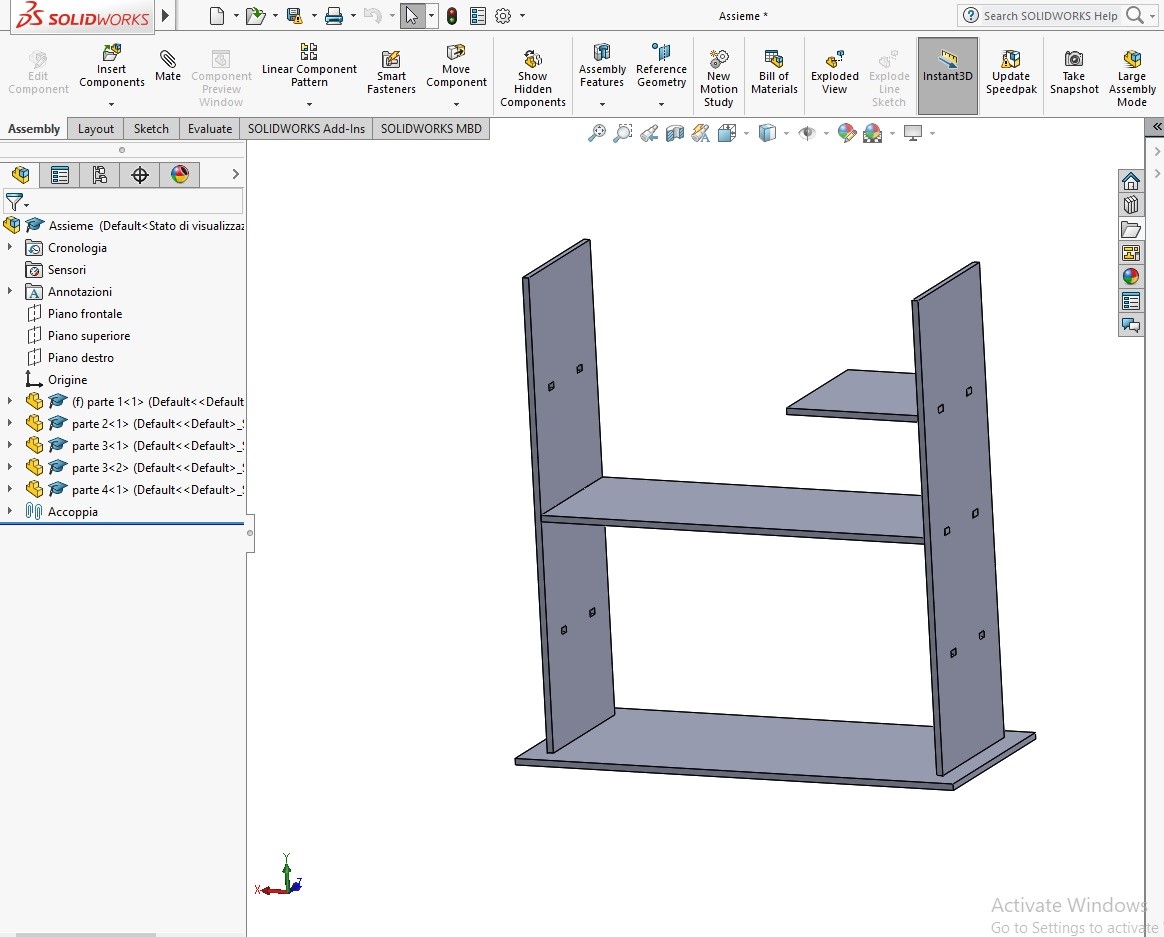
When I assembled everything together I noticed that the shelves were not straight, so I made a support and I glued it underneath, in this way the result is improved.
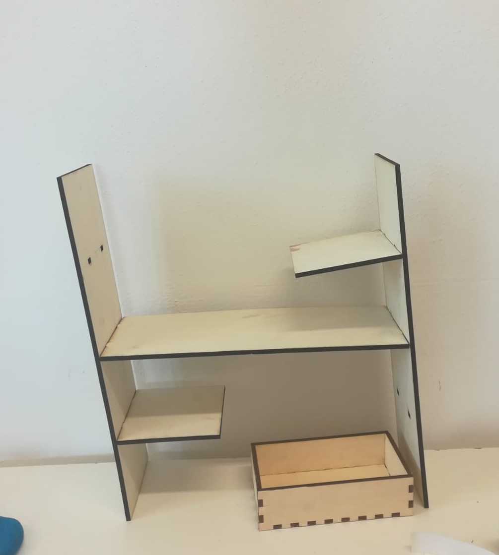
And this is the final result. To give it a different look I used the blue spray paint. The purpose of a parametric kit is to maintain the same proportions thanks to the equations. In this way I can make this object in any size I want without changing each measure one by one. The modularity of this object consists in choosing the disposal of the shelves according to your needs.