Week 11: Output devices
Group assignment: measure the power consumption of an output device
Individual assignment: add an output device to a microcontroller board you've designed, and program it to do something
Individual assignment: add an output device to a microcontroller board you've designed, and program it to do something
This week we have to create a board with an output device and since it does not lack much at the end of the Fab Academy
and therefore the development of the final project I decided to take me forward and create parts that could serve me in its realization, especially I intend to use a
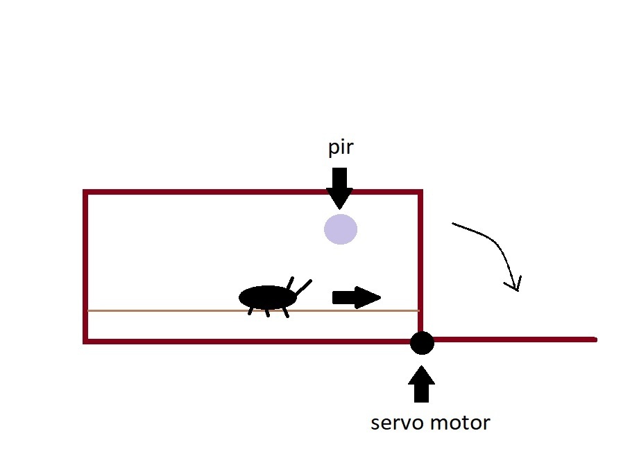
servo motor to create a sort of drawbridge to move insects from one area to another
Servo motor and schematic
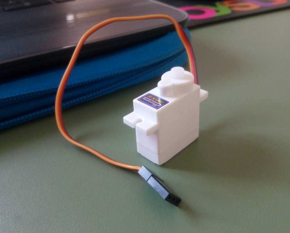
I started looking for the features of my servo motor, in lab we have the 5V one by hobby king.
On the site I found this specifications:
- Torque: 1.4kg
- Weight: 10g
- Speed: 0.09 / 60deg
- Voltage: 4.8v
- Operating voltage cannot be higher than 5V.
Like in the previous week, this component has VCC, GND and Data cable, but this time we have to program the board in order to make our component do something.
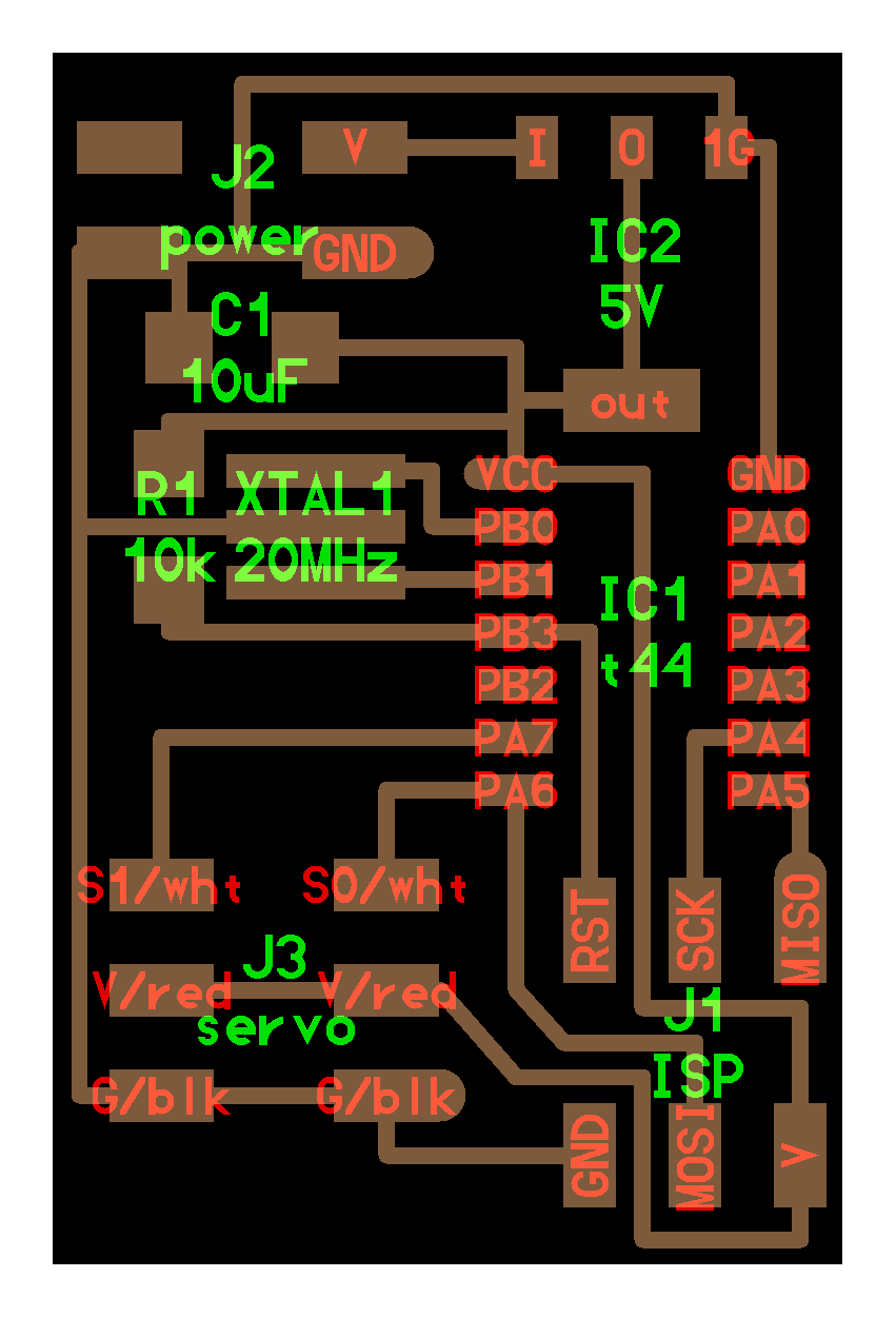
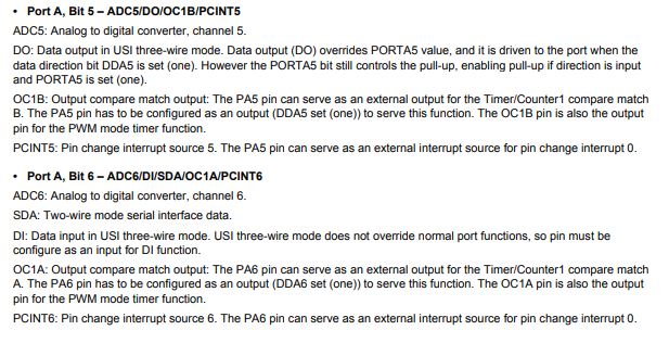
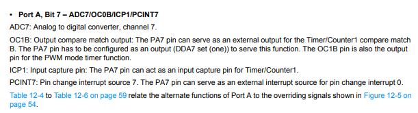
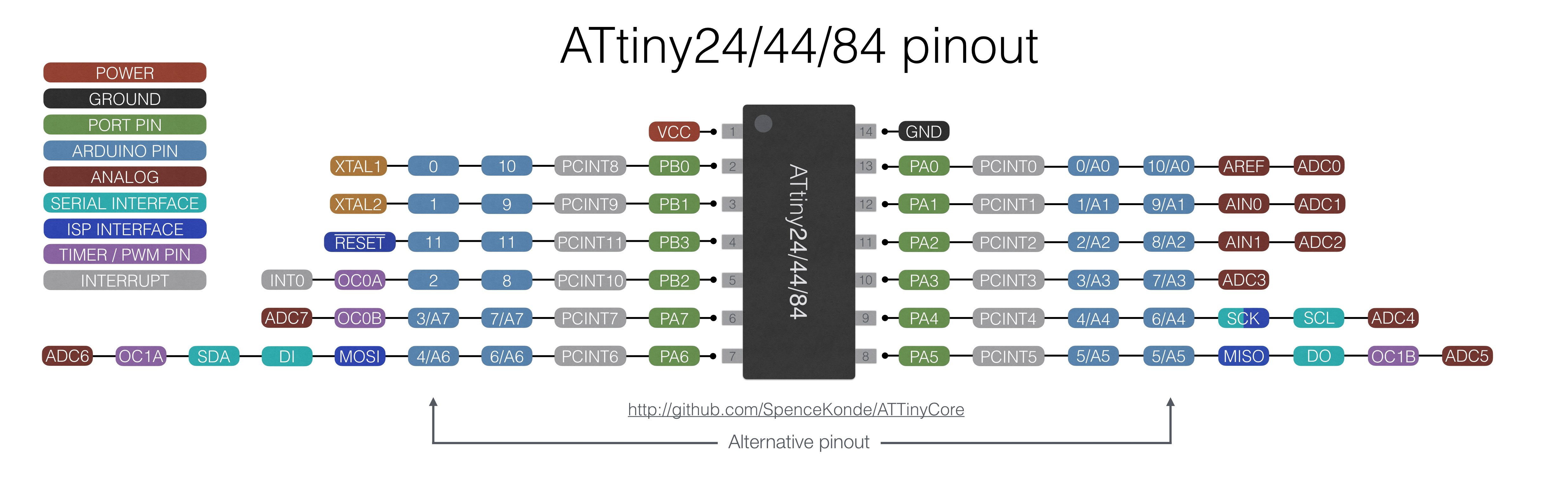
Looking at this video of Neil's board and I figured out how to attach the servo to the board and noticed that the data pin was connected to pins PA7 and PA6. I read the datasheet of ATtiny44 and it says that the output pinout are PA5, PA6 and PA7. Below the extract from the datasheet
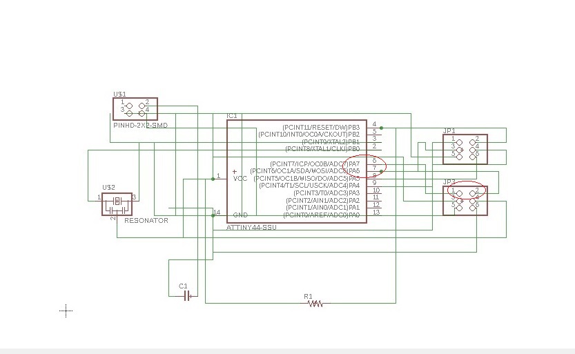
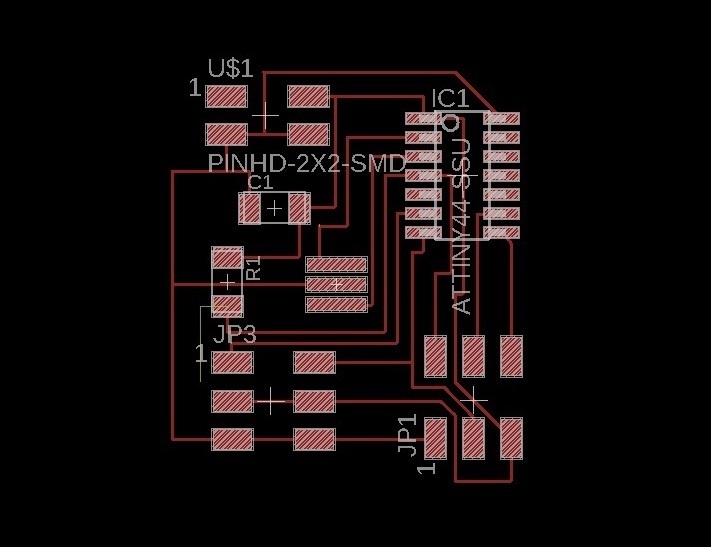
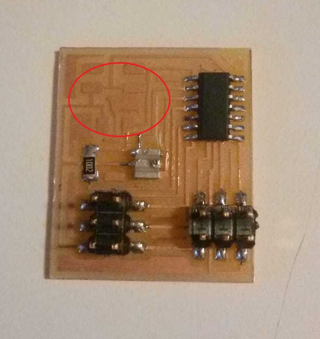
As I approached to solder the board I had doubts about the Voltage regulator (IC2 5v), so I asked Simone for advice and he explained to me that being able to directly supply the board with 5 volts current a regulator was not strictly necessary, so I decided to not include it in my board (consequently there is an empty space)
Programming with Arduino
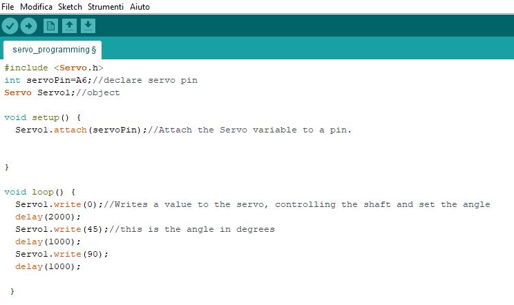
Now it's time to program. Not being accustomed to programming and still having a lot to learn I searched on the internet for projects already
done with arduino ide and a servo motor, in order to have an idea of what commands I will need. I found this video very useful and I made
the same sketch but changed the servoPin, in fact in my case the pinout 7 is A6 on IDE.
.
The servo works and I didn't particular difficulties this week (maybe because I did something very simple)
the next step will be to join the servo to a motion sensor
Final result