Molding & Casting
Things to do:
Have I achieved this week's goals?
Molding & Casting
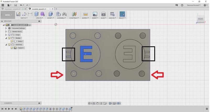
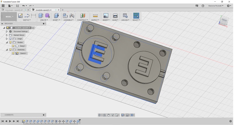
First of all, I measured the dimensions of my wax block piece and then I started drawing my 3D model on Fusion 360. Considering the fact the piece of material hadn't regular sides, I decided to focused my attention on its internal section. In this way, I would have been sure to have the same spaces to mirror my model on the 3D software. After that, I decided to create a keychain with my name's initial. So, I used small dimension and thickness to be closer to reality shape and this also gave me the opportunity to have extra time to try different casting materials. Before exporting the file in .stl extension, I made sure of joints (bivalve model) and to have built the refief valve in a correct way.
After that, I exported the file and I saved it on my USB pen. Next, I opened it on Vectric - CUT 3D and that was the most difficult activity because it includes two essential kernels: parameters settings (pass depth, stepover, spindle speed, feed and plunge rate) and the choices related to the mill points (diameter and main features) you decide to use for the roughing and for the finishing. In fact, I decided to do a quick sum up to understand them properly.
(high percentage means you need more time to mill)
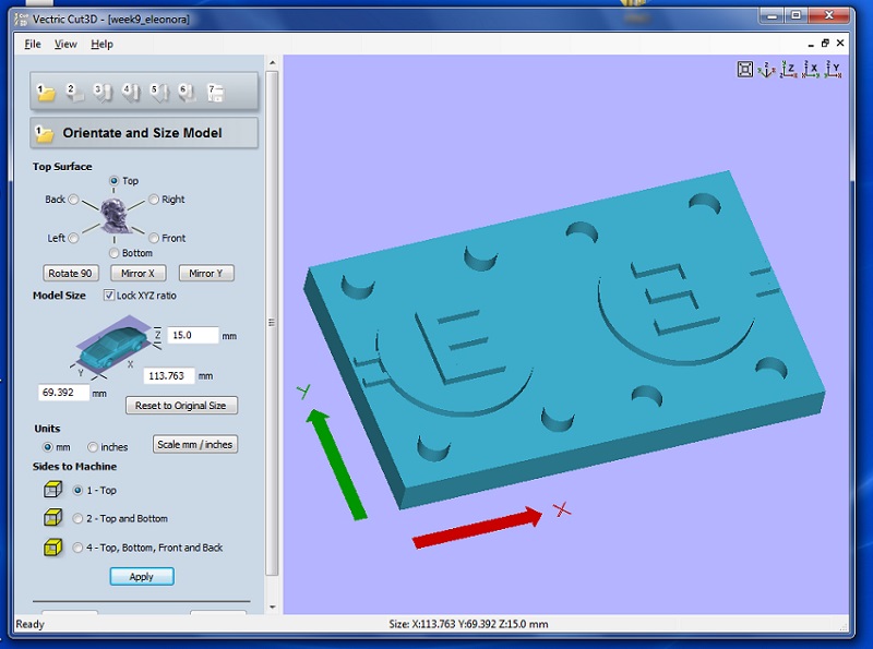
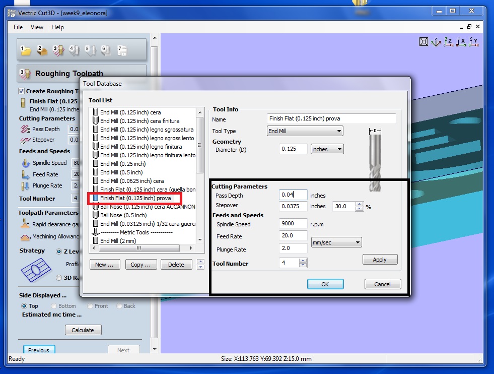
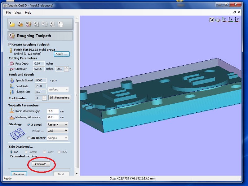
First of all, I orientated mt model and I looked at its dimensions. I set the unit of measurement in millimeters and I selected the top option to see my model on the software. Then I set the origin on the lower left corner and I also added come millimeters to depth. This is a fundamental step because it will give the real thickness of your model shape. No less importantly is the tip's choice. I decided to use the End Mill: 0.125 inch and I set the following parameters:
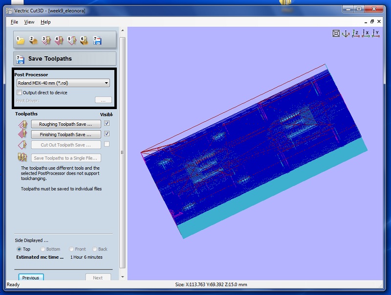
Then, the software gives you an overview of settings. After having checked the parameters, I clicked on calculate and I received an estimated time related to the milling action. At the end, I saved the toolpaths (roughing and finishing) as Roland MDX-40 mm (*.rol) files.
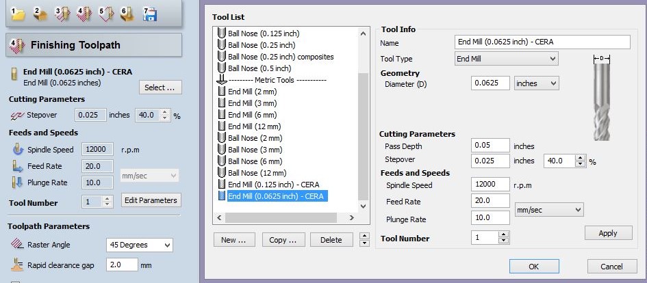
As I've already shown, there are some previews of the values I set on Cut 3D. Probably, I did a mistake when I set the finishing toolpath, because I chose the 3/32 tip and my instructor said to me I would have been chosen a more precise one. Maybe 1/16? It probably would have been better. I would have obtained a more polished result because it make the milling machine to repeat the finishing route. Despite that, I'm going to show you the finishing parameters I set on Vectric - CUT 3D.
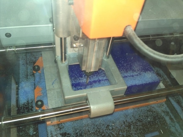
Then, I started milling my wax block piece and...in order to avoid emergency stop from the Roland Machine, it is important to well set the feed rate and to clean the excess material. It allows the tip to work without any kind of overload.
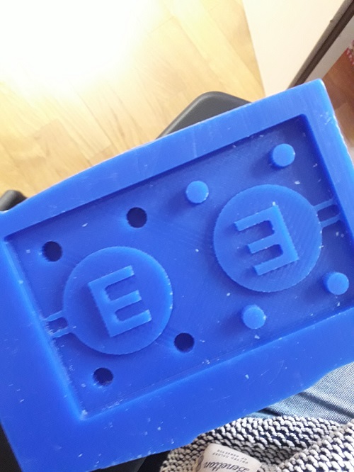
Anyway, the final result was quite good, with only an other exception. In fact, I didn't leave enough space between the highest part of my "E" and the rectangular edge. For this reason, I decided to create a ceiling moulding around my whole shape. I simply took some wooden stiks. I proceeded cutting their extremities (because they were rounded) and I put them together with the hot glue. I know it is aestethically terrible, but there was the fastest way to solve the oversight!
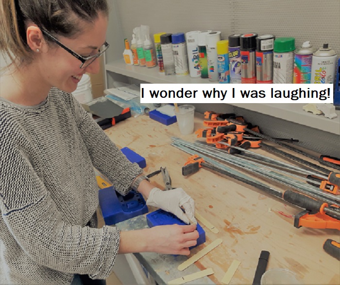
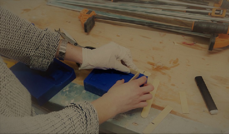
After that, I used the OMOO silicon and I started setting the table with the needed tools: gloves, mask, plastic glasses, wooden sticks and so on and so forth! As you can see in the pictures below, I used a small quantity of material because of the dimension of my mould. When I finished the needed steps, I poured the mix and I left a plastic glass with a small quantity of materials (and the wooden stick too) because I thought it would have been useful to see when the cure time was finished.
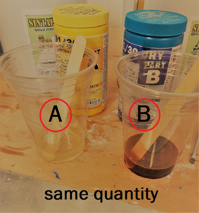
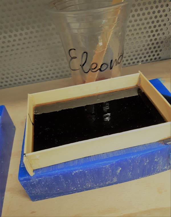
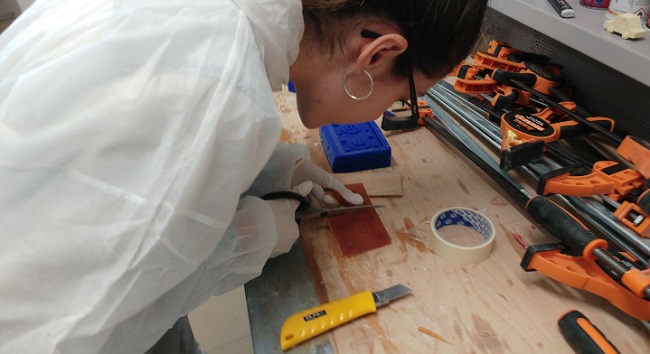
It is really important to understand the essential role of quantities: you can't be approximate with casting materials. The correlation between part A and part B is 1 to 1 and doing so, you avoid the risk to create something too soft (or liquid) or something that solidify in a short time. In addition, you have to use two different wooden sticks to blend them before the final mix. Finally, I suggest to pour the part B in the first one, but only because is more liquid and it's easier to get them together. Anyway, after 16 hours (cure time), I can show you how it came! ;) After having seen the result, I separated the bivalve mould using a cutter and I also tried to define the edges with a pair of scissors.
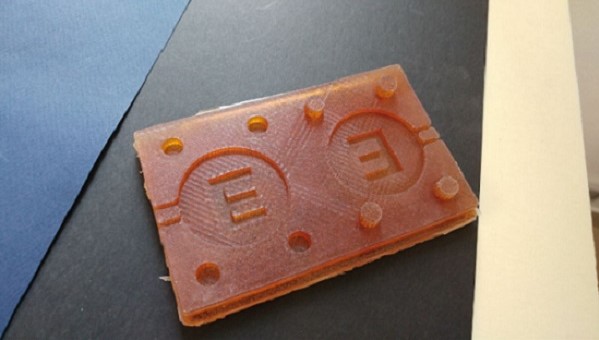
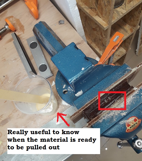
Furthermore I decided to put the resin inside my mould. Before starting, I sprayed a bit of releasing (Teflon) on the mould: doing so, the resin keychain has been removed easily. Then, I joined the bivalve model and I put it inside a bench vise and I left the little drills on the highest part. I used them to pour the resin inside the mould using a little funnel. Obviously, you have to control when the resin is visible from both drills. Consequently, it means your mould is full of material and you have only to wait the cure time. (Suggestion: leave the plastic glass to observe when the resin is ready to be pulled out. Keep in mind the process is really fast and you have to wait at least twenty minutes!).
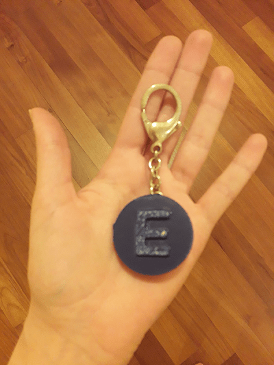
Finally, I pulled out my resin keychain and I decided to use a bit of bluemarine acrylic spray to colour it.
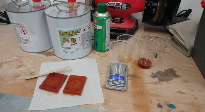
Considering the fact I had a bit of extra time, I also tried the silicone rubber AL20, and so I poured a little quantity of material in a clean plastic glass and I added the 5% of catalyzing agent.
Before the catalysis
Part A: white colour / dense
Part B: transparent / liquid
Combine: 100:5 (= 5%)
During the catalysis
Pot life: 30-50 minutes
Cure time: 24h
After the catalysis
Hardness: 20 shore
Lengthen: 500% (very high!)
You must mix very well in order to avoid bubbles and it is recommended to rotate the glass instead mixing as when you prepare a cake. What else? I'm really curious to see the final result and I would like to make some glitter decorations on the resin keychain.
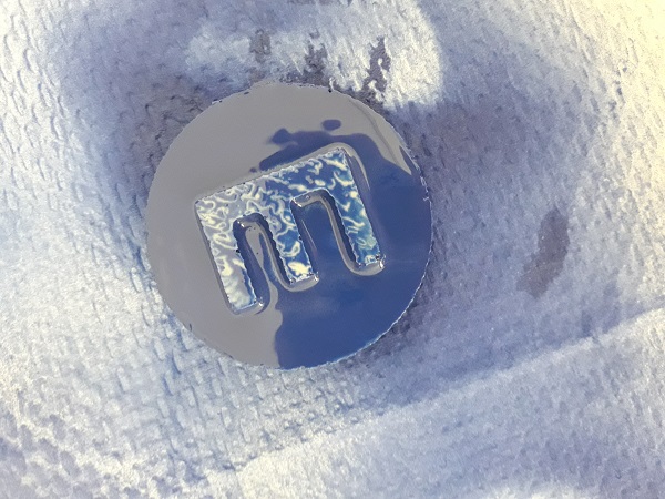
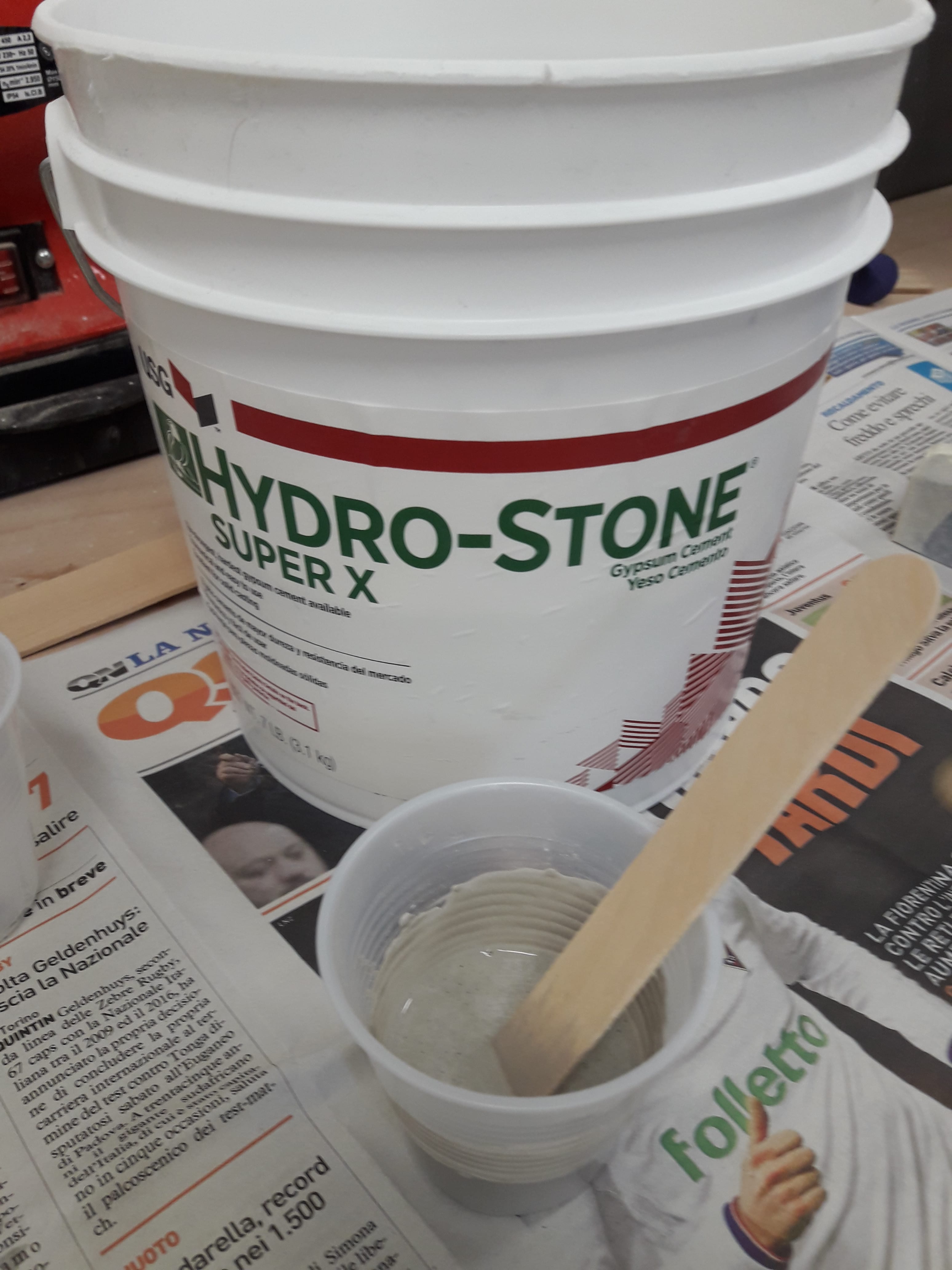
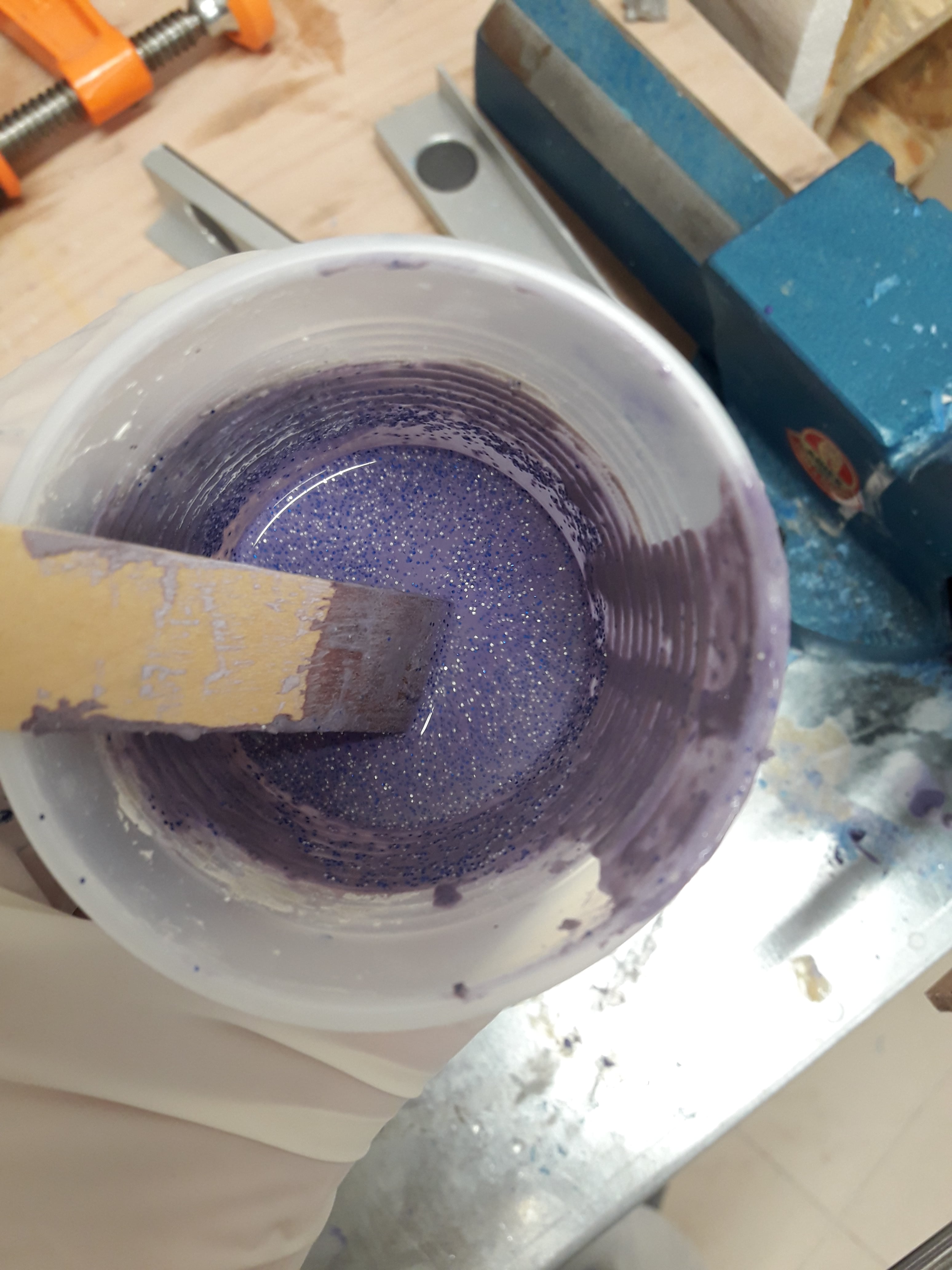
As I've already shown in the picture above, my blue keychain in resin is quite good and then I would like to drill it to add a little chain. Anyway, after few days full of chocolate, I tried to use my new mould made of white silicone rubber (cure time: 24 hours = Easter holidays for him too) with a different casting material: cement, purple dye and many many silver glitters :) . So, I started cutting the newest mould I did and I took the tools I needed: two plastic glasses, two wooden sticks, dry stone jar and plastic gloves. First of all, I poured a bit of water in the plastic glass. Then, I added the cement little by little and in the meanwhile I tried to mix water and casting material. After few minutes, I added a small quantity of purple dye and a glitter rain!
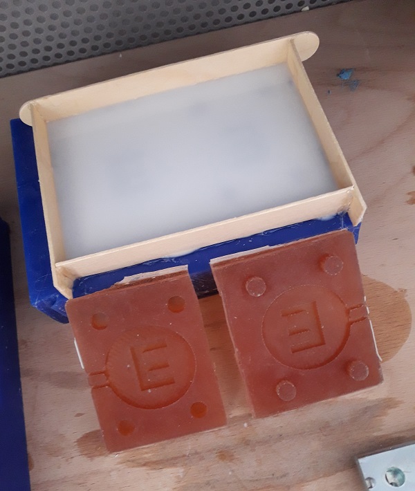
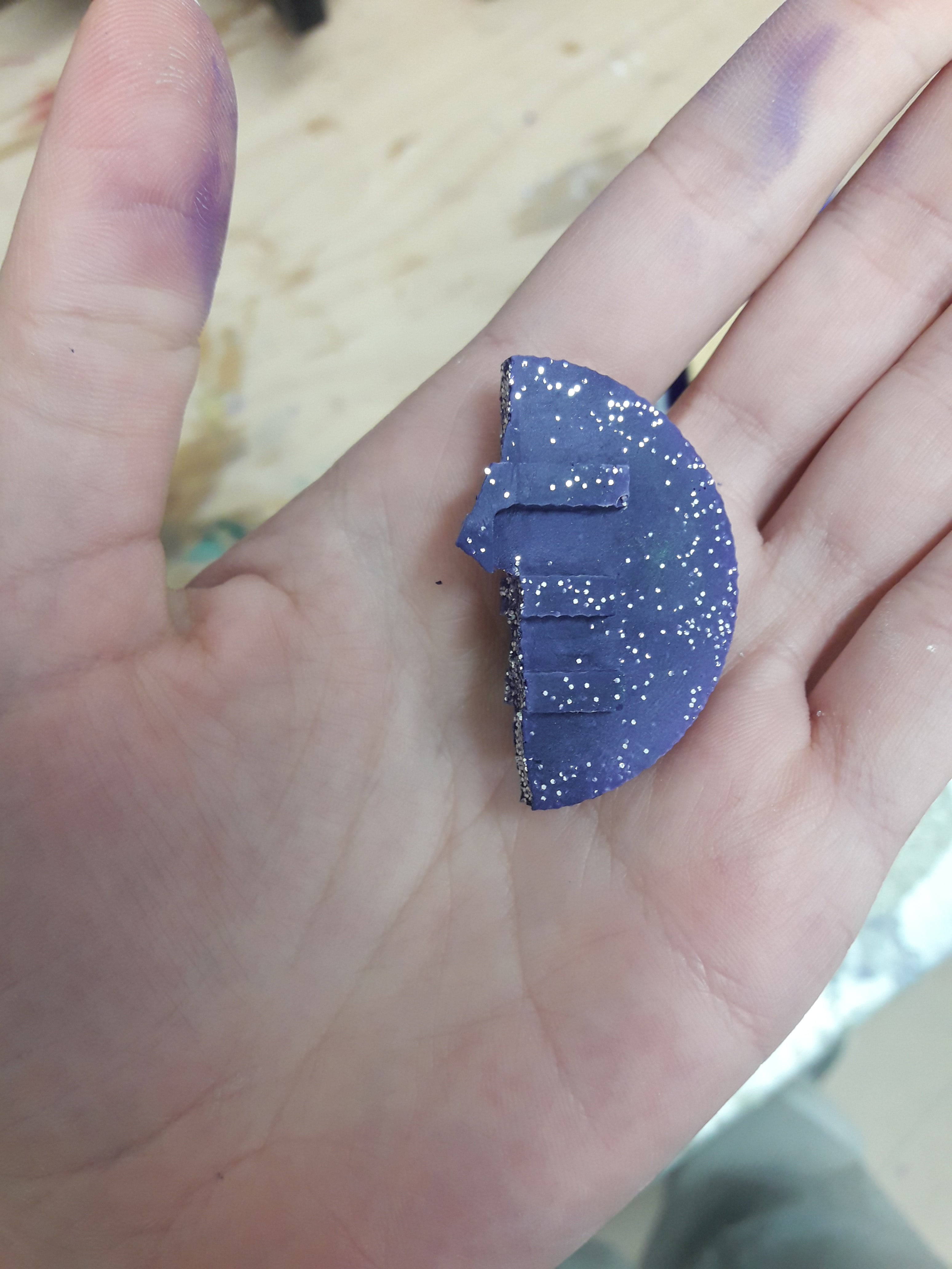
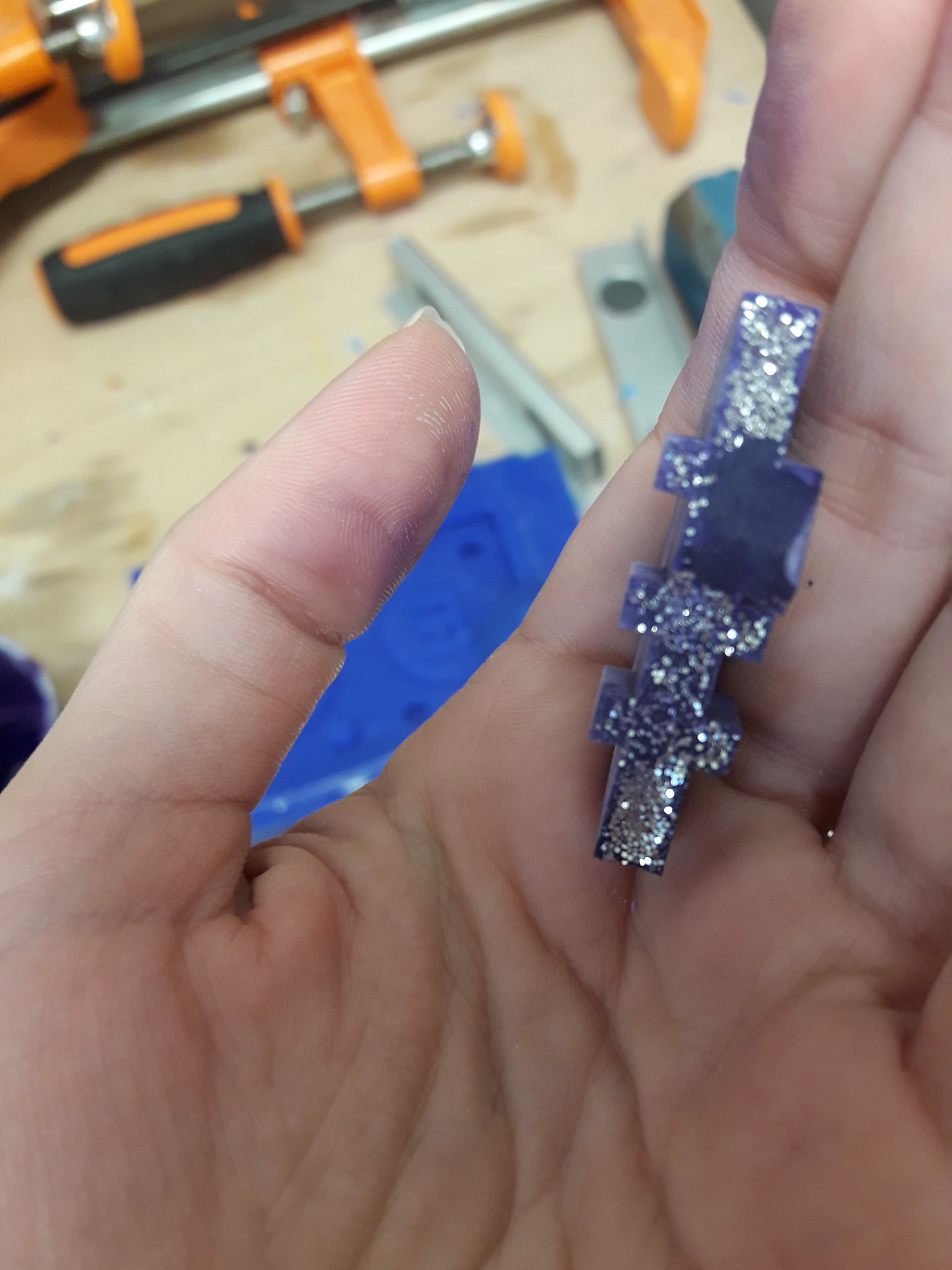
The mixture was good, but I had some problems related to the mould's drills. In fact, considering the fact I did a small object, I kept my relief valves proportioned to the whole shape. This doesn't change the fact I have been some problems to pour my casting material inside te bivalve mould. I tried to do a little paper cone to be helped during this action. Honestly, it worked better with the resin casting. This time, the keychain shape isn't real because I obtained a half figure! Anyway I noticed the hardness was good and the colour wasn't bad at all (glitters included). I will try again in order to understand which is the main problem about this incomplete shape.
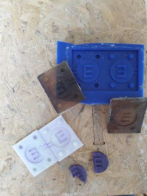
Here there's a picture related to the cast and mould parts. The final object isn't finished yet because I would like to make a small drill on it: doing so, it will be my car's keychain.
Conclusion
I really enjoyed this week because it properly mixed some theoretical concepts and practical activities. I spent some fun hours inside my lab and I was really curious to learn something in this field. I noticed you have to follow a precise workflow. In other words, you absolutely can't step off passages. For example, if you use silicon, you have to be cut the mould before and prepared two wooden boards to press it inside the bench vise. Consequently, you can't be aproximate (especially in terms of percentage and quantities). In addition, it is fundamental to read the safety datasheet for casting and molding materials. I did it as a group assignment before starting working and that's why I mentioned things like gloves, masks and so on.
Useful links:
Vectric 3D Cut - (Step by step guide)Molding and casting tutorials
OOMOO
