Computer-controlled machining
Things to do:
2) Make something big!
Have I achieved this week's goals?
Draw your model!
I decided to create a piece of furniture for my bathroom. I'd like to complete the making process with some details linked to shabby chic style. I love it so much and I'm really into this kind of design. This week, I tried using the license of Autodesk, in particular, I retried Fusion 360. I didn't appreciate it during the previous weeks, so I wanted to try it again. I noticed I had understimate it, because it is really well-organised. It has few sections but allows you to work tidly. Thanks to the drop-down menu, you can choose the actions you want to do. I didn't create complex shapes, because they weren't required. But the work has been demanding because it was the first time I finished a 3D modeling with this software.
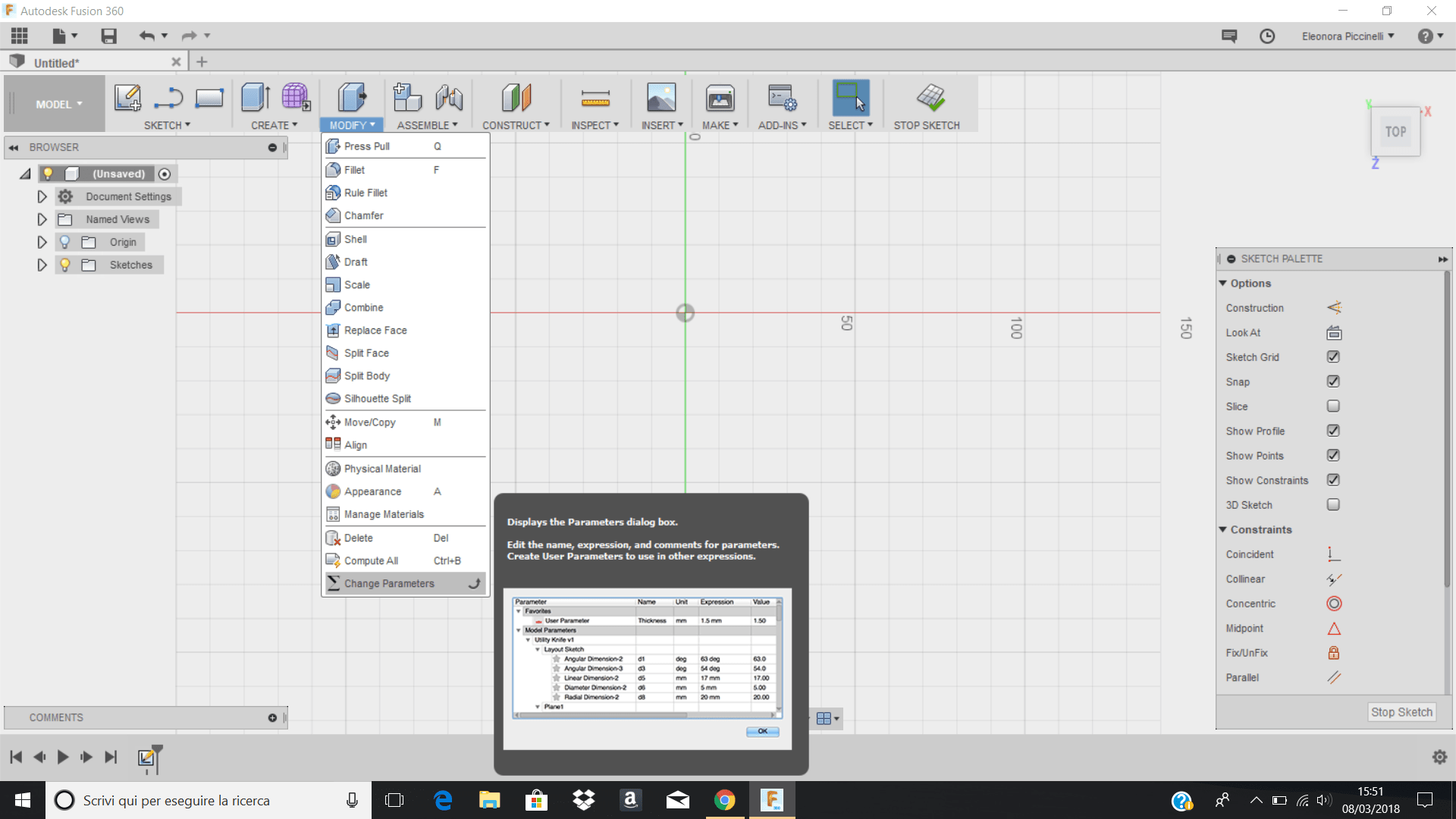
First of all, I started modeling my object and I set the parameters to build a parametric model. I clicked on Modify ---> Change parameters and I set the values I wanted (I decided to set them with the values I would have in the real scale). This week I wholly understood the aim of parametric modeling. I know that, theoretically, it's not a difficult concept, but I better noticed it during this week than the previous ones. Anyway, I started drawing my shapes on the sketch and I gave them the parameters I set before.

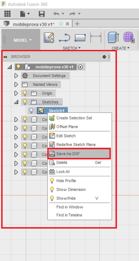
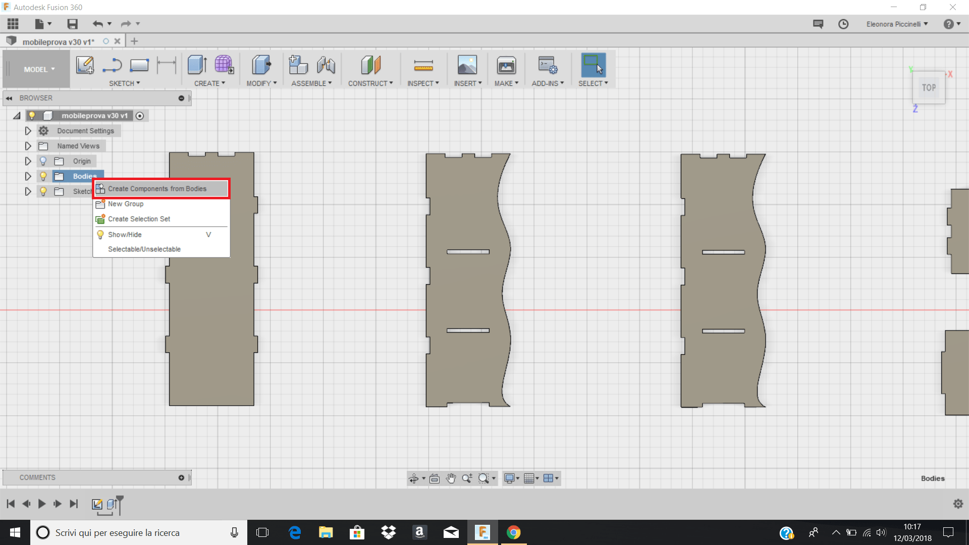
Next, I used the Joint command. I thought it was easier and you have to pay attention to the axis and plane you're working on. Wait a moment! After the extrusion, I thought I would have done the assembling. I got wrong! In fact, you have to click on bodies (on the left side) and select the option create components from bodies. Doing so, you'll select all the extrusions you did and you can proceed with the assembly work.
N.B: The next two pictures would have been inverted, but in this way, I can show you which was my processing idea.
Thanks to them, you can avoid the mistake I did and you can easily follow the right procedure at the first time!
(In other words, create the bodies and then do the joints!)

After that, I finally did the joints. I've never thought the essential command was at the bottom of the working area. So, clicking on the icon I highlighted with the red rectangle, you can change your point of view and looking fot the right component you need to do the joint. If you move your position too fast, the effect reminds you of a travel sickness, but if you keep press the shift button on your keyboard and you click the left button on the mouse, the rotation through the axis will be more enjoyable. After having done all the joints, I changed the values and I exported the shapes in .dxf extension.
Finally, I changed again the paramaters and I set them as they were at the beginning (in fact, I worked with the dimensions I wanted on the real scale!).
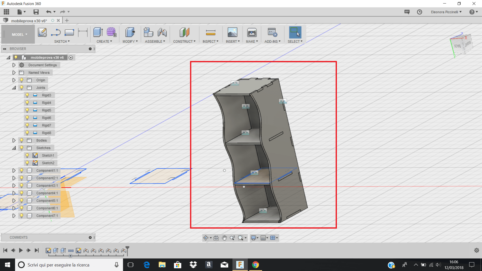
Here, you can see the object's preview! :) As you can see, the joints are good! Next step? ShopBot!
ShopBot
So, before starting, we did a general overview of the tools needed.
I went to our FabLab's carpentry with my colleagues. Thanks to the guidance principles provided by Matteo Sirizzotti and Pietro Rustici, I understood the importance of safety in this room and the attention you need to pay in using the ShopBot Machine. Even if I found the VCarve software a bit complex, I was really curious to use the machine. I noticed the clever way to link the wrench (that screw and unscrew the mandrel) and the key that allows the ShopBot starting/switching off.
The use of the equipment requires some essential things:
>> Attention
>> Coverall
>> Safe glasses
>> Mask
>> Tied back hair (ponytail or chignon)
Instead of its complexity and the safety guidelines, this week was amazing! After having drawn the model I measured the dimension of the OSB wooden panel. It was 250mm * 125mm * 18mm and considering the fact the weekly's aim was related to "make something big!" I already noticed my components were too many. If I would have been cut all of them, I had to scale the dimension of the whole object. So, I decided to find a quick solution! I'm going to delete one of my panels: in other words, I will cut the four shelfs (one is the support, one will be used at the top and the others will be place in the middle) and the vertical panels with the waving shape! So, the final object won't have a backside panel. Maybe...it won't be bad at all: it will have a modern style! Doing so, my piece of furniture will have the dimension I had in mind and it will respect the weekly assignment.
IMPORTANT FORMULAS:
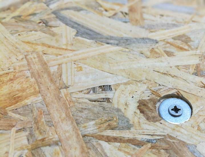
Getting to the point, it was time to cut the model! :) First of all, I fixed the OSB wooden panel to the machine's MDF layer. Using the drill, I made some holes close to the edges and I used them to put my screws (3 * side) to block the wooden panel to the machine's layer. Before milling, it is recommended to launch a test cut. Doing so, you can see if the endmill hits your screws or washers. If you paid attention to the previous steps, you wouldn't have been problems.
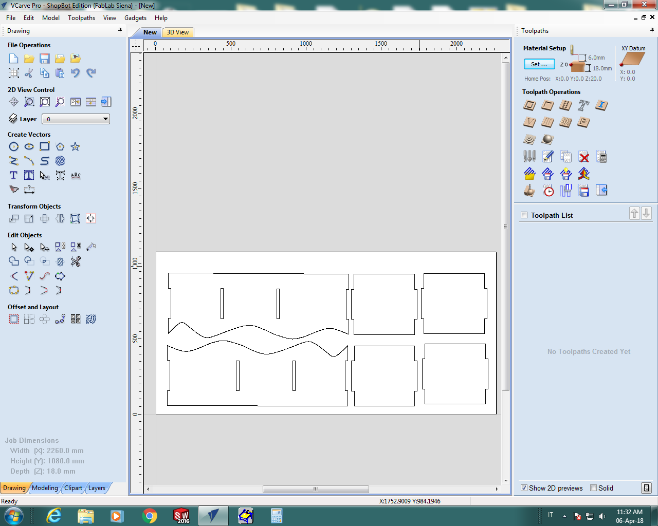
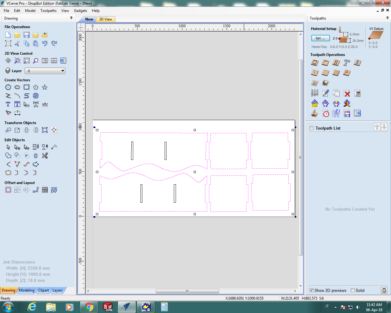
Now, let's see how to manage the drawing model on V-Carve software. First of all, I set the canva's sizes and then I opened my .dxf file on Adobe Illustrator to well organize the parts that have to be milled. After that, I simply joined contour lines, checked joints dimensions and exported the file with a different extension: you have to use it the .dwg. So, I opened the V-Carve software and I clicked on Create New File. I set the material thickess to 18mm and after having checked the machine orientation (our ShopBot has the X and Y axes inverted) you can set the milling starting point.
I created the t-bone holes with the VCarve program directly on the corners of the cuts. They are essential if the model have squared angles and the option I've already mentioned allows the tin to cut the object in the correct way. Without the t-bones the angles would be rounded and the whole object will be milled with a different type of joints. In addition, after having selected the model, I also create the tabs. They are one of the most important thing to set! In fact, they maintain the milled parts fixed on the panel. Otherwise, you could see some wooden pieces come off from the main board.
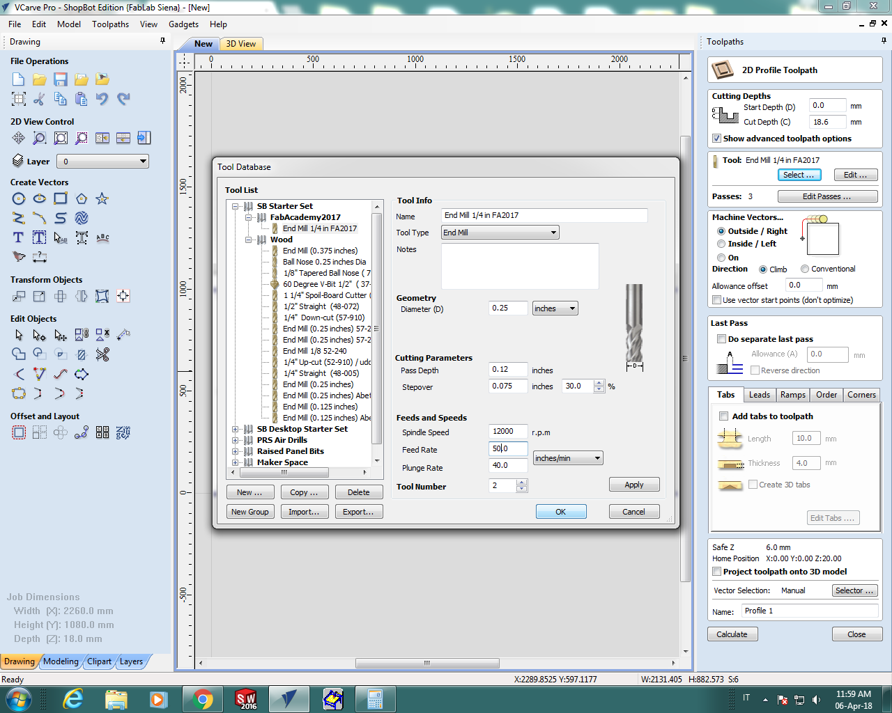
Last but not least! I chose the tin I wanted and I set the values you can see in the screenshot below:
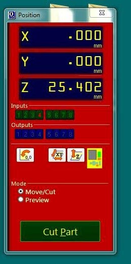
After having set the values, I was ready to cut my model! I went on the keypad panel and I set X, Y and Z origin axis. First of all, I moved the spindle with arrow buttons and I stopped the movement only when I reached the desired position. Thanks to the panel you can move the machine. Next, I did the following passages: 1) Go through Zero --> zero [X] axis 2) Do the same for the Y axis

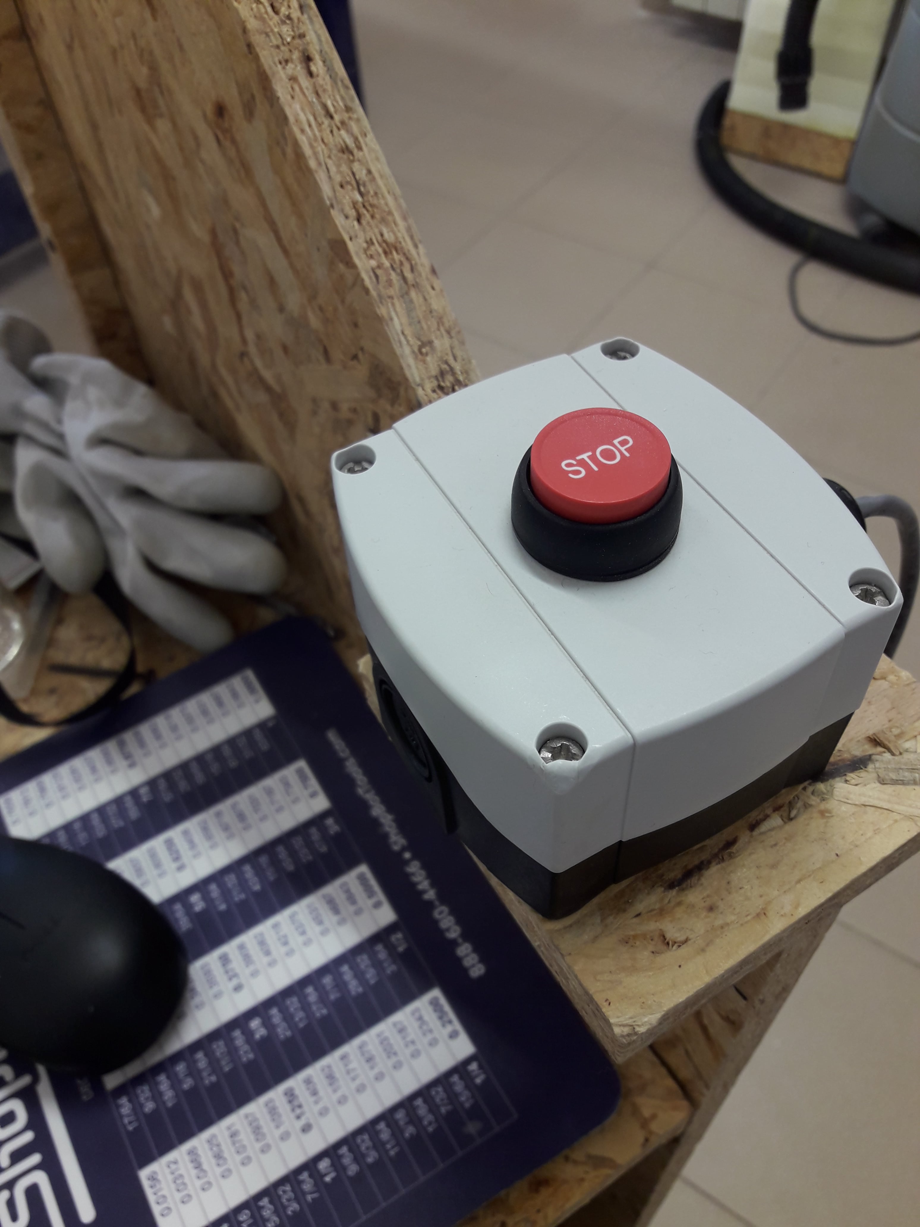
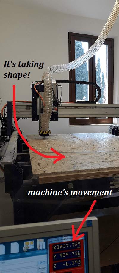
Now...let's cut parts! You will see the machine's movement on the screen panel and the estimated time to finisch the whole cut. In addition, keep the STOP BUTTON in your hands and BE PATIENT! :)
Conclusion
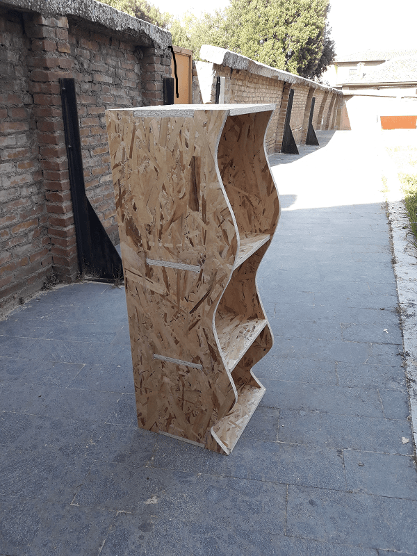
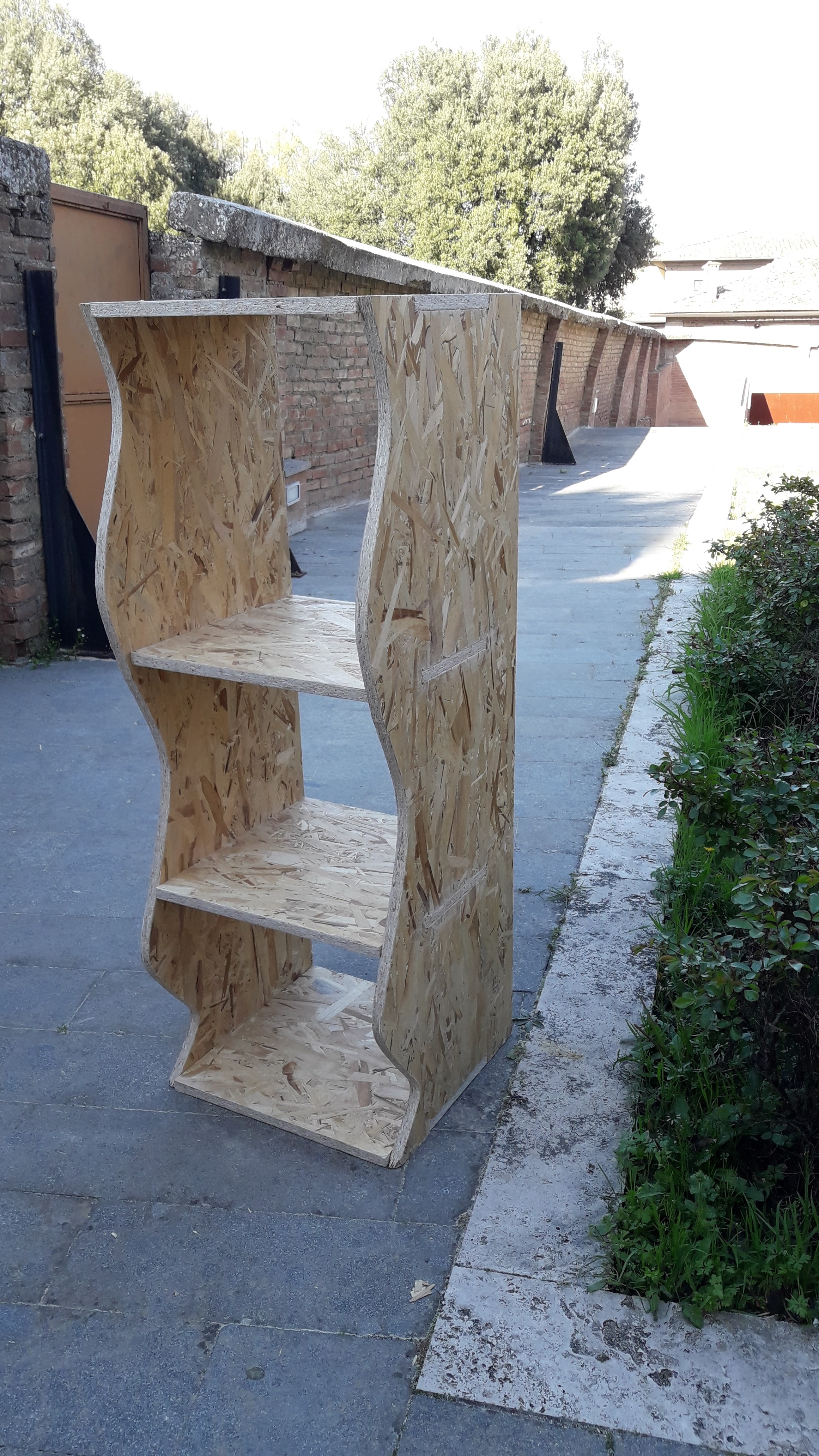
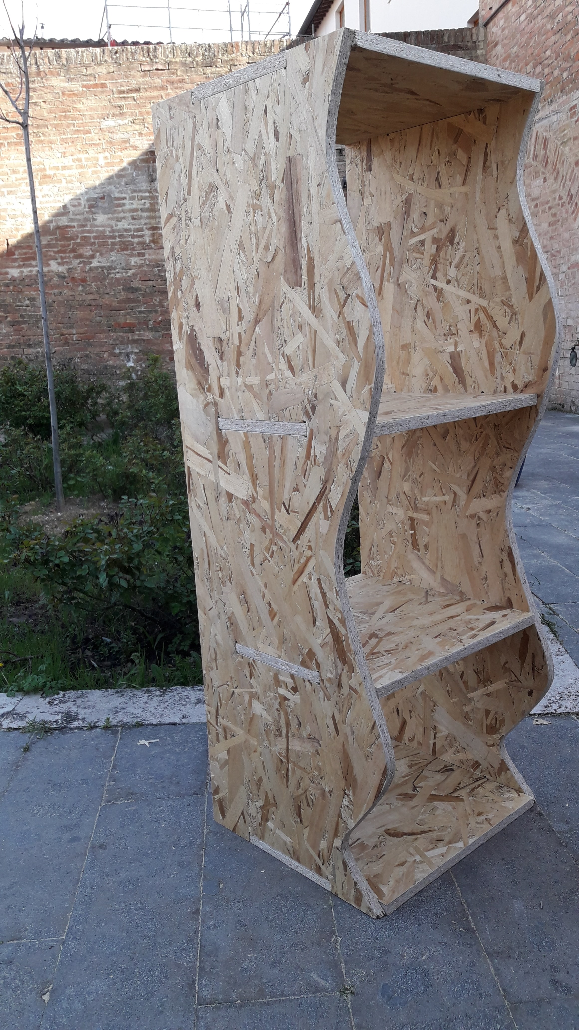
This was the funniest part! I was really curious to see how the piece of furniture came. This week will remain one of my favourite! After having finished the cut, I took the whole wooden panel and I pulled it out from the machine board. I noticed that 6 passes were enough, maybe...too many, because my pieces were completely detached and I didn't use chisel and hammer to move them away. Anyway, I used the sand paper to level the edges. After that, I started assembling my pieces. The joints are good, even if I used the hammer to fix them. The final result was very satisfying.
Useful links:
V-CarveShopBot
Chipload tables
How can I do the joint on Fusion?
How can I export my model on .STL/.DXF extensions?

